Labrie OPTIMIZER 2007 User manual


OPTIMIZERTM
OPERATOR MANUAL
Author: Labrie
Release Date: 1/31/07
Part #: 90320


Part #: 90320 iii
Table of Contents
Introduction
Introducing the OptimizerTM .................................................................. 1
Product Overview ...................................................................... 1
Contacting Labrie Environmental Group .............................................. 3
Plant information ....................................................................... 3
Labrie Customer Support Center .............................................. 3
Chapter 1 Safety
Safety Conventions ................................................................................. 5
Responsibilities of the Employer ............................................... 5
Responsibilities of the Employee .............................................. 6
Lockout/Tagout ....................................................................................... 6
Protection Against Fire ........................................................................... 7
Location of Safety Labels ....................................................................... 8
Chapter 2 Controls on the OptimizerTM
Parking Brake .......................................................................................... 9
Pump Switch ............................................................................................ 9
Joystick .................................................................................................. 10
Packer Controls ..................................................................................... 11
Red Button .............................................................................. 11
Green Button ........................................................................... 12
Yellow Button .......................................................................... 13
Hopper Roof Gate Switch ....................................................... 13
iv Part #: 90320
Tailgate Switch ........................................................................ 14
Chapter 3 Operating the OptimizerTM
Approaching the Vehicle ...................................................................... 17
Starting the Vehicle ............................................................................... 17
Inspecting the Body .............................................................................. 19
Collecting Refuse with the OptimizerTM .............................................. 20
Packing Refuse in the Body .................................................... 23
Unloading the OptimizerTM ..................................................... 23
Cleaning the Hopper of the OptimizerTM ............................................. 25

Part #: 90320 1
INTRODUCTION
INTRODUCING THE OPTIMIZERTM
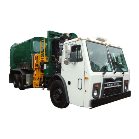
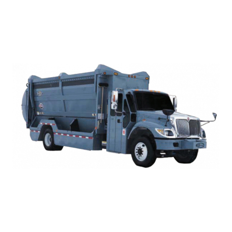
The OptimizerTM is a front load refuse collection vehicle. It picks up dumpsters from two to
ten cubic yard volume and dumps their content into its body. Once the body is full, all its
content is unloaded on a waste management landfil. This vehicle is conceived to be
operated by only one person at a time and uses a series of hydraulic, pneumatic,
mechanic, and electrical systems to perform its work routine.
Figure 1. OptimizerTM
Product Overview
The OptimizerTM is made up of a 36 to 40 c.y. body, depending on the model, mounted on
a chassis and a set of automated arms and forks to perform the collection of industrial
and commercial waste.
The body’s main components are the hopper, the packer and the tailgate. The hopper
being the area of the body receiving the waste, the packer being the element that
compresses the waste inthe body and the tailgate beingthe component allowing waste to
either stay in the body or to come out when unloading.

2Part #: 90320
Figure 2. Body’s main components
On the other hand, there is the chassis with its cab being the controls room. In the cab
you find the controls console housing most of the switches, light indicators and levers that
control most of the functions of the OptimizerTM. Also in the cab, you find one or two
joysticks to control the funtions of the arms and forks (See "Joystick" on page 10).
Then, there are the automated arms and forks which help you pick up solid refuse
containers and dump their contents in the hopper of the OptimizerTM.
Figure 3. Arms and forks
HOPPER PACKER TAILGATE

Part #: 90320 3
CONTACTING LABRIE ENVIRONMENTAL GROUP
Plant information
Address 175 du Pont
St-Nicolas (Quebec)
CANADA G7A 2T3
Phone: 1-800-463-6638
(418) 831-8250
Fax: Sales Dept.:
(418) 831-5255
Service & Warranty:
(418) 831-1673
Parts:
(418) 831-7561
Labrie Customer Support Center
Address 3596 Stearns Drive
Oshkosh, WI 54904
Hot Line Technical Support, Service & Warranty:
24-Hour Service
1-800-231-2771
Parts:
8 am through 7 pm ET 1-800-231-2771
Web Site: www.labriegroup.com
E-mail: [email protected]
IMPORTANT
FOR TECHNICAL SUPPORT AND PARTS ORDERING, THE SERIAL NUMBER OF YOUR
VEHICLE IS REQUIRED, THEREFORE, LABRIE ENVIRONMENTAL GROUP
RECOMMENDS TO KEEP RECORD OF THE INFORMATION FOUND ON THE VIN PLATE
WHICH IS LOCATED IN THE CAB.


Part #: 90320 5
SAFETY
Being a heavy duty vehicle, the use of the OptimizerTM entitles a number of safety issues.
Such issues, along with all necessary safety instructions and conventions, are presented
in this section of the Operator Manual.
SAFETY CONVENTIONS
Responsibilities of the Employer
It is the responsibility of the employer:
• To ensure the operation of the OptimizerTM is in accordance with all safety
requirements and codes, including all applicable regulations, the Occupational Safety
and Health Act (OSHA) and the American National Standards Institute (ANSI).
• To ensure the employees are qualified for the operation of the equipment and take all
safety measures before working with this equipment.
• To properly maintain all mobile equipment to meet all provincial/state and federal
safety standards.
• To supply adequate instructions and training for the safe use of the vehicle before
assigning the employee to such equipment.
DANGER
INDICATES AN IMMINENTLY HAZARDOUS SITUATION WHICH, IF NOT AVOIDED, WILL
RESULT IN DEATH OR SERIOUS INJURY.
WARNING
INDICATES APOTENTIALLY HAZARDOUS SITUATION WHICH, IF NOT AVOIDED, COULD
RESULT ON DEATH OR SERIOUS INJURY.
CAUTION
INDICATES APOTENTIALLY HAZARDOUS SITUATION WHICH, IF NOT AVOIDED, MAY
RESULT IN MINOR OR MODERATE INJURY.

6Part #: 90320
• To keep the vehicle maintained and properly adjusted to meet the manufacturer’s
standards and recommendations. For help or more information, contact the
manufacturer or any authorized representative.
• To keep record of any breakdowns or malfunctions of the vehicle as well as any
inspection and maintenance.
• To ensure the repair of any failures or malfunctions that may affect the safe use of the
vehicle, always before it is used again.
• To meet the appropriate lighting requirements for night shift work (if permitted).
• To regularly accompany the operator of the vehicle and take measures to ensure the
smooth and safe operation of the vehicle.
• To make sure that the backup alarm works properly while the vehicle is in reverse.
• To take the necessary measures that follow a damage or malfunction report from any
employee.
• To establish and ensure the application of a “Lockout/Tagout Procedure” at the time of
any inspection, repair or maintenance to the vehicle, whether it takes place on the
road or in the garage.
Responsibilities of the Employee
It is the responsibility of the employee:
• To enforce all safety measures to meet the requirements established by the employer.
• To operate the OptimizerTM only after having received instructions and training.
• To immediately report to the employer or supervisor about any damage or malfunction
of the vehicle.
To make sure that there is nobody near the vehicle before activating any of the controls
and be prepared to stop everything upon the existence of possible danger.
LOCKOUT/TAGOUT
The Lockout/Tagout procedure must be applied to render the vehicle out of service and
thus ensure its safety and that of those who will be around it.
To lock out and tag out the OptimizerTM:
1. Apply the parking brake.
2. Turn off the hydraulic system and the engine.

Part #: 90320 7
Figure 4. Parking brake
3. Remove the key from the ignition switch.
4. Place the key in a safe and controlled area.
5. Cover the ignition switch with tape.
Note:If the OptimizerTM is equipped with a master switch on the battery set, you
must turn it off.
6. Put an OFF SERVICE tag on the driver’s wheel.
7. Put an OFF SERVICE sign on the front windshield.
8. Use a safety prop to block any system that could move by gravity. (Open tailgate,
etc.)
9. Drain all air tanks.
10. Move all control levers to release any residual pressure in the system.
PROTECTION AGAINST FIRE
It is mandatory to have an ABC-type fire extinguisher easily accessible from both, outside
and inside the cab.
Figure 5. Fire extinguisher

8Part #: 90320
LOCATION OF SAFETY LABELS
In the event safety labels need to be ordered and installed on the vehicle, the following
guide will help you with their corresponding part numbers and location.
Figure 6. Labels on the right-hand side
Figure 7. Labels on the left-hand side
47282
47260
47262
47270
47280
4756425286
47332
47334
47336
47266
47268
47422
47268
47266
43817
25286
47304
47564
47422

Part #: 90320 9
CONTROLS ON THE OPTIMIZERTM
The OptimizerTM has a series of controls that allow the user to more easily operate the
different functions installed on the vehicle. Such controls are mainly located in the cab
and the following is a description of each one of them.
PARKING BRAKE
The parking brake located in the cab, usually on the dashboard center, must be used
every time the OptimizerTM is stopped on idle position other than the regular traffic stops.
Figure 8. Parking brake
PUMP SWITCH
The pump switch turns on and off the hydraulic system of the OptimizerTM. It is located on
the console and is accompanied by a red light to indicate when the hydraulic system is
on. Such red light denotes a condition where the user must be aware that the hydraulic
functions on the OptimizerTM are available.
DANGER
ALWAYS BE AWARE OF THE SURROUNDINGS AND SURE OF THE TASKS TO
ACCOMPLISH WHILE THE RED LIGHT INDICATING PUMP ENGAGED IS ON. ANY
ACCIDENTAL PUTTING INTO MOTION OF THE HYDRAULIC COMPONENTS WILL CAUSE
SERIOUS INJURY OR DEATH IF YOU DO NOT COMPLY WITH THIS SAFETY NOTION.

10 Part #: 90320
Figure 9. Pump switch on the console
JOYSTICK
The joystick is used to control the arms and forks of the OptimizerTM. It is located to the
right-hand side of the driver. It is also possible to have two joysticks inside the cab. One is
used to control the forks and the other one is used to control the arms.
Figure 10. Joysticks
Pump switch

Part #: 90320 11
Figure 11. Single Joystick
PACKER CONTROLS
Three buttons located on the console control the different packer functions.
Red Button
The red button is an emergency feature. When pressed, it instantly cuts off all hydraulic
functions. Therefore, none of the systems such as the packer, tailgate or arms, just to
mentioned a few, moves at all avoiding thus injuries and damages.
Figure 12. Red emergency button on the console
Red emergency button

12 Part #: 90320
Green Button
The green button has two functions depending on the circumstances the packer is used.
• To start the packer for a full extend/retract cycle to pack refuse on the body.
For such use, you press it once and the cycle is automatically completed.
• To start the packer for a complete extension stroke to eject the refuse from the
body. For such use, you press and hold it until you feel the packer has
reached the end of its stroke.
Figure 13. Green button on the console
Green button

Part #: 90320 13
Yellow Button
The yellow button has two functions.
• To start the packer for a complete retraction stroke after refuse has been
ejected from the body. For such use, you press and hold it until you feel the
packer has reached the end of its stroke.
• To retract the packer during the packingcycle when it doesn’t reach the end of
its normal stroke.
Figure 14. Yellow button on the console
Hopper Roof Gate Switch
The Hopper roof gate switch controls the opening and closing of the hopper roof gate. It is
located on the console and accompanied by a green light to indicate when the hopper
roof gate is fully open. Such a green light indicates a condition that has to be met to be
able to use the arms. In other words, if the roof gate is not fully open, the arms and forks
will be inoperable.
Yellow button

Figure 15. Roof gate switch on the console
Tailgate Switch
The tailgate switch controls the opening and closing of the tailgate. It is located on the
console and accompanied by a red light to indicate when the tailgate is fully open and a
red light to indicate when the taigate is unlocked.
• The red light indicating the tailgate is fully open denotes a condition that has to be met
when unloading the body of the OptimizerTM. That is, the packer will not extend to eject
the refuse unless the tailgate has been fully open.
Figure 16. Tailgate switch on the console
• The red light indicating the tailgate is NOT locked denotes a condition that has NOT
been met and therefore, an alarm is sent out. Other hydraulic functions on the
Roof gate switch
Roof gate open light
Tailgate switch
Tailgate fully open light
Tailgate unlocked light
Table of contents
Other Labrie Utility Vehicle manuals

Labrie
Labrie Top Select User manual

Labrie
Labrie Pendpac WITTKE RETRO FL User manual

Labrie
Labrie AUTOMIZER FULL EJECT User manual

Labrie
Labrie expert 2000 User manual

Labrie
Labrie Top Select User manual

Labrie
Labrie AUTOMIZER HELPING-HAND User manual

Labrie
Labrie Pendpac WITTKE RETRO FL User manual

Labrie
Labrie AUTOMIZER FULL EJECT User manual

Labrie
Labrie expert 2000 User manual