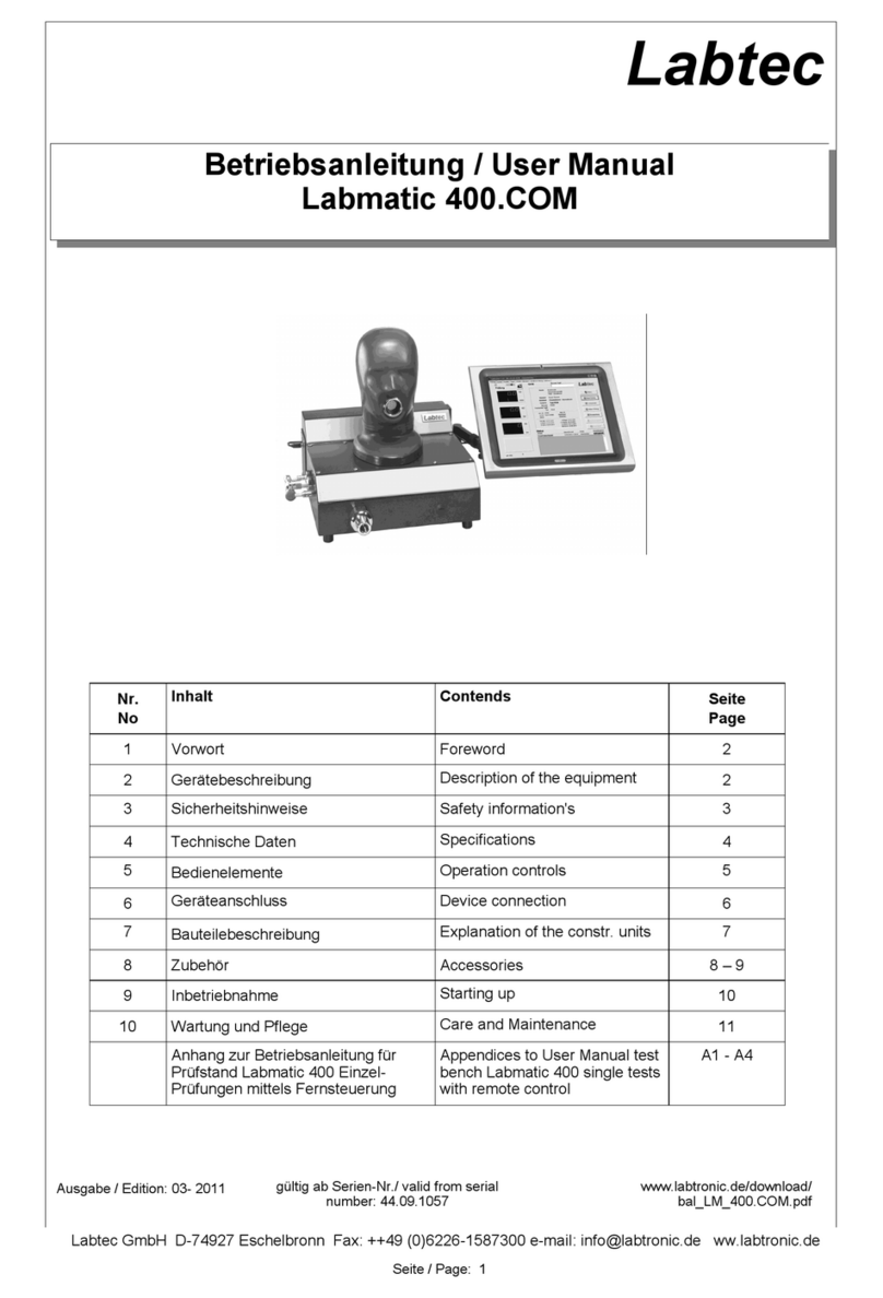
LABTEC LabModul 240 Series User manual

User Manual LabModul 240 Page 1 www.labtec.de
User Manual
LabModul 240
Labtec
No Content Page
1foreword 2
2safety instructions 2
3device description 3
4technical data 3
5operating elements 4
6component description 5
7description of the operating elements 5
8commissioning 6
9care and maintenance 6
Attachments: Performing Tests Manually
A 1 testing full-face masks 7
A 2 testing demand valves 8
A 3 testing breathing apparatus 9
A 4 testing CPS 10

User Manual LabModul 240 Page 2 www.labtec.de
1. foreword
This operating manual describes the operation
of LabModul 240 series of test instruments.
Labtec test devices are professional tools that
require comprehensive respiratory protection
expertise, e.g. by completing training as a re-
spirator maintenance technician, to ensure
proper operation and correct measurement.
A prerequisite for proper operation of the de-
vice is that the device is operated and used
exclusively in accordance with these operating
instructions. Labtec is not liable for personal
injury or damage to property or consequential
damage of any kind if the device is used in a
manner other than that described in this manu-
al. The same applies to the acceptance of any
warranty and guarantee claims.
Otherwise, the terms of sale and delivery as
well as the warranty and guarantee conditions
of Labtec GmbH apply, which are not exten-
ded in any way by these instructions.
2. safety instructions
Each Labtec test device requires device-
specific instruction by an authorized Labtec
employee or training partner.
The device may only be operated by instructed
and authorized personnel.
The device may only be serviced and repaired
by trained and certified Labtec service techni-
cians. Only original spare parts and accessori-
es must be used.
The device may only be opened by a Labtec
service technician or, if expressly requested,
under instruction by a Labtec employee.
To ensure proper functioning of the device and
thus a correct measurement result, the device
must be serviced at least once a year by a trai-
ned and certified Labtec service technician
and tested and calibrated by him or her using
a Labtec calibration device.
The list of current, certified employees, training
partners and service technicians is updated
daily and is available from Labtec or on the
Labtec homepage.
Labtec devices are partly operated with brea-
thing air in the high pressure range of up to
400bar. Operating a device under high pres-
sure requires the greatest care. Before
connecting and disconnecting a test item / bre-
athing apparatus, the test bench must always
be completely depressurized and air supply
lines, especially the main valve, closed.
The device connection must always be che-
cked. Devices must always be connected
completely correctly. When connecting to the
high pressure device connection, the device
thread must be completely screwed to the in-
ternal thread of the device connection.
Before switching off the test device electrically,
the test bench must first be completely depres-
surized and vented and then all connected de-
vices and any full face masks must be remo-
ved.
Never test dirty demand valves or masks on
the test head. There is a risk of dust particles
getting into the measuring system, which can
impair the function.
When the test stand is started up, the mouth
opening and the instrument connections must
remain open, otherwise self-calibration will be
incorrect and the measurement data will be
incorrect.
The test device must be set up horizontally
and rest well on all support buffers.
Care must be taken to ensure that the measu-
ring nozzle in the mouth opening in the test
head is not clogged. In case of false measu-
ring values in low pressure, the opening can
be cleaned with a 0.2 - 0.35 mm needle.
In case of queries or uncertainties
contact the Labtec customer service!

User Manual LabModul 240 Page 3 www.labtec.de
3. device description
LabModul 240 are electronic test devices to
be operated via a PC for the testing of brea-
thing masks according to DIN EN 136, self-
contained breathing apparatus (SCBA) ac-
cording to DIN EN 137 and chemical protecti-
ve suits (CPS) according to DIN EN 943-1.
The tests are performed in the low (-50 to 50
mbar) and medium pressure measuring range
(0 to 20 bar).
For testing other breathing apparatus or che-
mical protective suits, contact Labtec. Only
breathing air according to DIN EN 12021 may
be used.
Module T Control panel with LCD display and
membrane keyboard for manual operation of
the device.
Module COM Freely positionable touchscreen
PC, connected to test device via swivel arm
mounting, incl. pre-installed LabNet Profi test
software
The device is also available as model MT. The
model LabModul 240 MT has no interface to
the LabNet Profi operating software but is de-
signed for purely manual operation without PC
support. The LabModul 240 MT has the stand-
ard operating panel of option T. The interface
can be retrofitted at the factory.
Connection requirements
A 230-240 V / 50-60 Hz power supply is requi-
red to operate the test stand.
As medium pressure connection Euro-coupling
and nipple are available as standard. If units
with other coupling connections are tested, ap-
propriate intermediate adapters must be used.
Please contact the manufacturer of the units
for this.
Scope of delivery and accessories
The scope of delivery of the device includes a
power supply cable and a USB cable.
Adapters for the connection of CPS, regulators
and sealing caps for respirators must be or-
dered separately depending on the connection
used (e.g. ESA, PE45, RD40, manufacturer-
specific connections).
Labtec offers a wide range of accessories for
test devices.
The range includes test adapters for adapting
all respiratory protection devices on the mar-
ket, quick release devices for quick device
adaptation as well as holders for holding hel-
met-mask combinations
4. technical data
Medium pres-
sure connec-
tion:
EURO coupling and nipple 0...20 bar
Medium pres-
sure sensor: Measuring range
precision 0...25 bar
± 0,5 %
Low pressure
sensor: Measuring range
precision -50.0.+50 mbar
± 0,05 %
Dead space approx. 480 ml - w. o. Adapter
Power
Transformer Input: 230 V AC
Output: 24 V DC
Dimensions ~ B 460 x H 490 x D 430 mm
Weight: approx. 21 kg

User Manual LabModul 240 Page 4 www.labtec.de
5Bedienelemente 5Operation Controls
5. operating elements
A
B
C
F
G
H
D, E
1 LCD Display Low Pressure Display
2 LCD Display Medium Pressure Display
3 Inflate test head, sensing valve
4 Empty test head, tactile valve
5 Generate overpressure 5 l/min, sensing valve
6 Generate vacuum 5 l/min, push button valve
7 Relieve low pressure, sensing valve
8 Exhalation 10 l/min, switching valve
9 Inhalation 10 l/min, switching valve
10 Fill CPS, switching valve
11 Empty CPS, switching valve
12 Relieve medium pressure, tactile valve
Atest stand housing
BPanel (optional)
CTest head / breathing connection
DMedium pressure Device connection (plug
nipple)
E Medium pressure regulator connection
(coupling)
F CPS - Filling connection and device
venting
G Power supply 230 V AC with switch
H USB interface
I LED USB signals reception
J LED USB signals transmission
K LED + 24 V present
L ED + 5 V present
H
I
J
K
L
1, 2
3
4
5
6
7
8
9
10
11
12
or operating terminal via the test software

User Manual LabModul 240 Page 5 www.labtec.de
6. component description
Test stand housing (A)
Thanks to its ergonomic design, the test stand
can be operated fatigue-free even during con-
tinuous operation. Operation in computer mo-
de is via PC keyboard and mouse or manually
via the optionally available front panel.
Front panel (B) (optional)
The front panel contains the control buttons
and a multi-function LCD display showing print
and system information.
The following abbreviation is used:
LP = Low pressure (-50...+50 mbar)
MP = medium pressure (0...25 bar)
Multifunction probe (C)
The test head is a fixed head that can be infla-
ted by an electric pump so that full face masks
of any make can be sealed without problems.
A measuring point is installed in the test head
which measures the internal pressure in the
mask or lung automat.
Medium pressure device connections (D, E)
Plug nipple for connecting the medium pres-
sure line of the compressed air breathing ap-
paratus pressure regulator to be tested.
Quick coupling for connecting the medium
pressure line of the regulator to be tested.
CPS test connection and system vent (F)
Quick coupling for filling CPS. For all other test
procedures, the coupling must be connected
to the supplied plug-in nipple/silencer for sys-
tem venting.
Interface (H)
The USB interface for data transfer to a PC is
located on the left side of the housing
(LabModul 240 MT has no function with the
manual device).
Vacuum pump
With the built-in vacuum pump, the required air
currents are generated and the probe is infla-
ted or deflated. The desired air flow rate can
be set in the software from 2...12 l/min.
Processor
The built-in microprocessor takes over the
control and signal conversion.
7. description of the operating elements
1
2
LCD multi function display
Digital display of status of operation
Display for low pressure (LP)
Display for medium pressure (MP)
3Push button for test head inflation
Pressing causes the test head to be inflated out
of the test head
4Push button for test head aspiration
Pressing causes the air to be aspirated out of
the test head
5Push button to generate positive pressure
Forcing pump +5 l/min is set in motion by press-
ing this button
6Push button to generate negative pressure
Forcing pump –5l/min is set in motion by press-
ing this button
7Push button for low pressure decompress-
ing
Pressing causes the air to be aspirated out of
the test equipment
8Switch button for forcing pump
Forcing pump +10 l/min is set in motion by
pressing this button. LED shows function.
Pressing button again switches it off.
9Switch button for forcing pump
Forcing pump -10 l/min is set in motion by
pressing this button. LED shows function.
Pressing button again switches it off.
10 Switch button for CPS inflation
Pressing causes the CPS to be inflated out of
the CPS, Medium pressure is needed in the test
bench.
11 Switch button for CPS deflation
Pressing causes the air to be aspirated out of
the CPS
12 Push button for medium pressure decom-
pression
Pressing causes the air to be aspirated out of
the test equipment

User Manual LabModul 240 Page 6 www.labtec.de
8. commissioning
When setting up the unit, make sure that it is
horizontal and rests well on all support buffers.
Establish power supply
Connect the power supply to a 230 V / 50-60
Hz power source using the supplied power
cable. Switch on the unit at the switch.
Establish connection to the PC (not with MT)
Install the LabNet Profi test software accord-
ing to the installation instructions. Establish the
connection between PC and test bench via
USB cable.
> See separate installation and operating
instructions LabNet Profi
Device connection (breathing mask)
The test head must be completely vented. The
breathing connection of the mask is closed
with a suitable sealing cap. Alternatively,
connect the mask to a suitable demand valve
and then make a device connection (SCBA).
The mask is put on the test head. The inner
mask should rest correctly on the nose of the
probe.
Then tighten the fasteners of the head mask
starting from the bottom. The test head can
now be inflated until a tight fit of the mask is
ensured. If necessary, readjust the mask.
Device connection (SCBA)
For tests in the medium pressure range, dis-
connect the medium pressure line of the
SCBA at the Euro coupling and connect it to
the plug nipple of the medium pressure device
connection and the line of the demand valve to
the EURO quick coupling of the medium pres-
sure device connection.
If the SCBA to be tested does not have a Euro
coupling, a suitable adapter must be used.
Please contact the compressed air breathing
apparatus manufacturer.
The demand valve is inserted into the mouth
opening of the test head using a suitable
adapter.
9. care and maintenance
The test instrument should be protected from
external harmful influences such as water, mo-
isture in the form of steam and dust.
The test head should be cleaned and maintai-
ned regularly. This can significantly increase
the service life of the search unit.
The test head should always be covered with
the enclosed protective hood after the instru-
ment has been used.
> See separate test head care instructions
The test device must be serviced at least an-
nually by a certified Labtec service technician.
The test device is recalibrated and deviations
in the previous test cycle can be excluded.
The maintenance is carried out with a special
calibration device.
The maintenance is confirmed by a calibration
certificate issued directly by Labtec. The main-
tenance may only be carried out by authorized
and trained service technicians.
In order to ensure a cost-effective and timely
maintenance, it is possible to conclude a main-
tenance contract with Labtec.
Further information and brochures
can be found at www.labtec.de

User Manual LabModul 240 Page 7 www.labtec.de
Test
step Operation Comments Controls
1.1.1 Wet the outlet valve rubber slice. Breathing con-
nection of mask close with the dust cap. Flutter valve must be thoroughly moist
1.1.2 Mount mask on test head, pull straps tight,
inflate test head (3) A few seconds is usually long
enough
1.1.3 Adjust negative pressure to exactly - # mbar
(6)
By means of pressure relief valve
(7)
1.1.4 Pressure increase after # min at the LCD (LP)
read off and compare with the nominal value
1.1.5 Deflate test head (4), remove mask
1.2.1 Wet the outlet valve rubber slice. Breathing con-
nection of mask close with the dust cap. Test only possible with tight-set A-
valve. Use mark specific adaptors.
1.2.2 Mount mask on test head, pull straps tight,
inflate test head (3) A few seconds is usually long
enough
1.2.3 Adjust negative pressure to exactly - # mbar
(5)
By means of pressure relief valve
(7)
1.2.4 Pressure increase after # min at the LCD (LP)
read off and compare with the nominal value
1.2.5 Deflate test head (4), remove mask
1.3.1 Mount mask on test head, pull straps tight,
inflate test head A few seconds is usually long
enough
1.3.2 Pump +10 l/min switch on.
1.3.3 Opening pressure at the LCD (LP) read off and
compare with the nominal value
1.3.4 Pump +10 l/min switch off (8).
1.3.5 Deflate test head (4), remove mask
1Leakage
1.1 Leakage test with open A-valve at --#mbar (standard test, should always be carried out)
1.2 Leakage test with sealed A-valve at +# mbar (performed to locate any leak detected by test 1.1)
1.3 Opening pressure of the outlet valve
A 1 testing full-face masks

User Manual LabModul 240 Page 8 www.labtec.de
A 2 testing demand valves
2Demand valve
2.1 Leakage: Pressure rise after # min at --#mbar negative pressure / overpressure
2.2 Tightness of the dosing valve: Pressure change with pending medium pressure to # min. at # mbar
2.3 Opening pressure / activating pressure on # l/min exhausting
2.4Static pressure / overpressure of demand valves
Test
step Operation Comments Controls
2.1.1 Couple demand valve to test head Use mark specific adaptors.
2.1.2 Seal the medium-pressure hose of the regulator
with a cap or connect it to the medium pressure
connection (E) on the device.
E
2.1.3 Test vacuum with pushbutton (6) to setpoint
- Set # mbar. Turn on the stopwatch.
If necessary, relieve with button (7)
and approach to setpoint.
and/or Test overpressure with push button (5) to set-
point. Set + # mbar. Turn on the stopwatch. If necessary, relieve with button (7)
and approach to setpoint.
2.1.4 Read off the pressure change on the LCD dis-
play (LP) after a specified time # min and com-
pare with the setpoint.
All further tests require high pressure!
Regulator in conjunction with a
Connect the SCBA to the test device.
Medium pressure hose from the PA
regulator of a SCBA must with
Device connection (D) to be connec-
ted.
D
2.2.1 Open the bottle of the SCBA . Medium pressure flows into the device
2.2.2 Close the bottle of the SCBA . Tester / DUT are under pressure .
2.2.3 Relieve low pressure with button (7) and set to
setpoint. Regulator must be closed, close if ne-
cessary.
2.2.4 Read off the pressure change on the LCD dis-
play (LP) after a specified time # min and com-
pare with the setpoint.
2.3.1 Open the bottle of the SCBA . Medium pressure flows into the device
and is in the device.
2.3.2 Switch on pump with switch (9) and flow of -10 l /
min. produce. until the regulator opens.
2.3.3 Read the opening / closing pressure of the regu-
lator on the LCD display (LP).
2.3.4 Switch off pump with switch (9).
2.4.1 With the bottle open, read the static overpres-
sure of the open LA on the LCD display (LP) and
compare with the setpoint.
Testing only for positive pressure regu-
lators
2.4.2 Close the bottle and relieve the medium pres-
sure with the button (12). at the end of the test or continue with
further tests.

User Manual LabModul 240 Page 9 www.labtec.de
3Pressure reducer
3.1 Medium pressure, static at # bar inlet pressure
3.2 Medium pressure, dynamic at # l/min ventilation
3.3 Medium pressure, dynamic at 10 l / min extraction (optional, not required by manufacturers)
Test
step Operation Comments Controls
3.1.1 Open the bottle of the SCBA . Medium pressure flows into the device.
3.1.2 Close the bottle of the SCBA . Tester / DUT are under pressure.
3.1.3 Read the medium pressure on the LCD display
(MP) and compare with setpoint.
3.2.1 Open the bottle of the SCBA . Medium pressure flows into the device.
3.2.2 Close the bottle of the SCBA . Tester / DUT are under pressure.
3.2.3 Read the medium pressure on the LCD display
(MP) and compare with setpoint.
3.2.4 After a specified time of # min, read the medium
pressure again and compare with the previously
measured value.
Compare difference value with allo-
wable deviation.
3.3.1 Open the bottle of the SCBA and leave it open. Medium pressure flows into the device
and is in the device.
3.3.2 Switch on pump with switch (9) and flow of -10 l /
min. produce. Regulator must be connected.
3.3.3 Read medium pressure on the LCD (MP) dis-
play.
3.3.4 Close the bottle and relieve the medium pres-
sure with the button (12). at the end of the test or continue with
further tests.
A 3 testing breathing apperatus

User Manual LabModul 240 Page 10 www.labtec.de
5Leakage
5.1 Leakage of the suit
6A-Valve
6.1 - Tightness test of suit valves No. 1 to 4 after # min. at - # mbar
6.4 (Repeat test according to the number of valves )
Test
step Operation Comments Controls
5.1.1 The suit-tightness test requires
medium pressure !
Connect the CPS to the tester in conjunction with
a SCBA.
Medium pressure hose from the regu-
lator of a SCBA must with
Device connection (D) to be connec-
ted.
D
5.1.2 Connect a tightening valve with test adapter,
seal all other tightening valves with plugs. CPS test adapter CGA 200 and manu-
facturer-specific adapter
5.1.3 Engage filling hose of the test adapter with plug
nipple in filling connection (F). CPS test adapter CGA 200 F
5.1.4 Engage filling hose of the test adapter with plug
nipple in filling connection (C). CPS-test adapter CGA 200 C
5.1.5 Open the bottle of the SCBA . Medium pressure flows into the device.
5.1.6 Press the switch (10) to inflate CPS. CPS is filled to> # mbar .
5.1.7 Press the switch (10) again to stop filling the suit. when the required internal pressure is
reached .
5.1.8 Lower the pressure to the required internal pres-
sure with the switch (11), if necessary with but-
ton (12) approach and turn on the stopwatch.
Setting the required Settling time.
5.1.9 If time has expired, lower switch (11), if necessa-
ry with button (12) to the required test pressure
and switch on stopwatch.
5.1.10 After a specified time of # min read off the low
pressure on the LCD display (LP) and compare
with the previously set test pressure.
Compare difference value with allo-
wable deviation.
5.1.11 Close the bottle of the compressed air respirator
and relieve the test system with the push button
(12), remove the test adapter
Open suit.
6.1.1
-
6.4.1
Engage filling hose of the test adapter into the
mouth opening of the test head (C). CPS test adapter CGA 200
C
6.1.2
-
6.4.2
Connect suit valves 1 to 4 one after the other
with valve test adapter from the inside brand-specific adapter,
depending on the number of the suit
existing valves .
6.1.3
-
6.4.3
Test vacuum with pushbutton (6) to setpoint
- Set # mbar. Turn on the stopwatch. If necessary, relieve with button (7)
and approach to setpoint.
6.1.5
-
6.4.5
After a specified time of # min. Read pressure
change on the LCD display (LP) and compare
with setpoint.
A 4 Testing gas-tight chemical protective suits (CPS)

User Manual LabModul 240 Page 11 www.labtec.de
Konformitätserklärung
Certificate of Conformity
Attestation de Conformité
Bezeichnung der Maschine: Prüfgerät
Type of machine: Test Equipment
Description de la machine: Instrument de vérification
Modell / Model / Modèle: Labtest / LabModul
Typ / Type / Type:
Geräte Nr. / instrument no. / Instrument numéro: 240 / 400 / 800 / 1000 / 1200 / 1600
Hiermit wird bestätigt, dass das Gerät den Anforderungen der Maschinenrichtlinie
2016/42/EG, sowie der EMV - Richtlinie 2014/30/EU einschließlich allen bis heute
veröffentlichen Änderungen bzw. Nachträgen entspricht. Das Gerät entspricht
folgenden Normen bzw. Richtlinien:
We do hereby certify that the above mentioned product meets the requirements set
forth in EEC-Guideline 2016/42/EG and EMC 2014/30/EU including all changes and
addendums to date thereto. The above mentioned product meets the following
standards and guidelines:
Nous Vous Confirmons que l’appareil cité ci-dessus correspond aux exigences des
directives 2016/42/EG ainsi qu’ à la directive CEM 2014/30/EU ci-inclus toues les
modifications ainsi que tous les suppléments publiés jusqu’à ce jour. L’appareil
mentionné correspond aux nomes cités ci-après :
DIN EN 60950-1, Ausgabe / dates / en date du 2014-08
DIN EN 135 Ausgabe / dates / en date du 1999
DIN EN 136 Ausgabe / dates / en date du 1998
DIN EN 137 Ausgabe / dates / en date du 2006
DIN EN 837 Ausgabe / dates / en date du 1997
Datum / date
01.01.2017
Diese Konformitätsbescheinigung wurde automatisch
erstellt und ist ohne Unterschrift gültig.
This calibration certificate was produced automatically
and is valid without signature.
Labtec
Gesellschaft für Labortechnik mbH
This manual suits for next models
3
Table of contents
Other LABTEC Test Equipment manuals