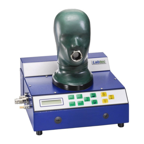
LABTEC Labmatic 400.COM User manual

Seite / Page: 1
Betriebsanleitung / User Manual
Labmatic 400.COM
Ausgabe / Edition: 03- 2011 gültig ab Serien-Nr./ valid from serial
number: 44.09.1057 www.labtronic.de/download/
bal_LM_400.COM.pdf
Labtec
Nr.
No
Inhalt Contends Seite
Page
1Vorwort Foreword 2
2Gerätebeschreibung Description of the equipment 2
3Sicherheitshinweise Safety information's 3
4Technische Daten Specifications 4
5Bedienelemente Operation controls 5
6Geräteanschluss Device connection 6
7Bauteilebeschreibung Explanation of the constr. units 7
8Zubehör Accessories 8 – 9
9Inbetriebnahme Starting up 10
10 Wartung und Pflege Care and Maintenance 11
Anhang zur Betriebsanleitung für
Prüfstand Labmatic 400 Einzel-
Prüfungen mittels Fernsteuerung
Appendices to User Manual test
bench Labmatic 400 single tests
with remote control
A1 - A4

Seite / Page: 2
1. Vorwort
Die vorliegende Betriebsanleitung beinhaltet die
Bedienung und Pflege der Prüfgeräte Labmatic
400.COM ab der vermerkten Seriennummer.
Voraussetzung für einen ordnungsgemäßen
Betrieb des Gerätes ist, dass ausschließlich nach
dieser Betriebsanleitung das Gerät bedient und
benutzt wird. Labtec haftet nicht für irgendwelche
Personen- oder Sachschäden oder daraus
resultierende Folgeschäden, gleich welcher Art,
wenn von der Bedienungsanleitung abweichend
das Gerät eingesetzt wird.
Das gleiche gilt für unsachgemäße Pflege,
Wartungen und Reparaturen am Gerät.
Labtec erkennt keine Gewährleistungsansprüche
an, wenn das Gerät durch nicht eingewiesene
Personen bedient oder gewartet oder repariert
wird, und wenn keine Original- Ersatzteile bei
Reparatur- und Wartungsarbeiten verwendet
werden. Desgleichen gilt beim Öffnen verplombter
Teile, ohne dass eine ausdrückliche Genehmigung
von Labtec vorliegt.
Im übrigen gelten die Verkaufs- und
Lieferbedingungen sowie die Garantie- und
Gewährleistungsbedingungen der Labtec GmbH,
die durch diese Hinweise in keiner Weise erweitert.
1. Foreword
Before starting up the equipment the instructions
for use should be read carefully, and they should
be observed in all matters.
The include instructions for operating and caring
for a Labmatic 400.COM test bench from the serial
number noted onward. It is essential to correct op-
eration of the equipment that it is operated and
used exclusively as described in these instructions.
Labtec accepts no responsibility for damages to
persons or property or for any late resultant squeal
if the equipment has been used in a manner that
deviates from the operating instructions.
The same applies to incorrect care, maintenance
and repairs to the equipment.
Labtec recognizes no claims under the guarantee if
the equipment has been operated, maintained or
repaired by persons who have not received proper
instruction and if original replacement parts have
not been used in repair and maintenance work.
The same applies if sealed parts have been
opened unless expressly permitted by Labtec.
Otherwise the sale and delivery conditions of Lab-
tec GmbH apply, which are in no wise extended by
these notes.
2. Gerätebeschreibung
Labmatic 400.COM ist ein Prüfgeräte zum Prüfen
von Atemschutzmasken nach EN 136,
Pressluftatmern, nach EN 137 und gasdichten
Chemikalienschutz-anzügen (CSA).
Die erforderliche Luftversorgung erfolgt über eine
300 oder 200 bar Atemluftflasche mittels spezieller
Adapter oder eine zentrale Luftversorgung 300 bar
die zum Betrieb dieses Prüfstandes erforderlich
sind. Ebenfalls zum Betrieb wird ein
Stromanschluss von 230 V AC benötigt.
Hardware—Voraussetzungen
Für den Protokollausdruck wird ein entsprechender
Drucker für DIN A 4 benötigt.
Für einige Prüfungen ist die Verwendung von
Adaptern oder Verbindungsteilen notwendig, die
herstellerspezifisch sind und von diesen bezogen
werden können.
2. Description of the Equipment
Labmatic 400.COM is designed to test full face
masks as per EN 136, Breathing Apparatuses as
EN 137 and Chemical Protection Suits (CPS).
The air required is supplied from a respiratory air
cylinder 300 or 200 bar by means of special
adapters that are essential for operation of this test
stand. Access to a 230 V AC power supply is also
needed for its operation.
Hard ware requirements
A printer taking A4 paper and compatible with this
PC running with the selected operating system
(see above) is needed to print out the protocols.
Some of the tests require the use of adapters or
connecting pieces that are specific to the manufac-
turers and can be obtained from them.
Für den Geräteanschluss sind am Labmatic
400.COM eine Euro-Kupplung und –Nippel
standardmäßig vorhanden. Werden Geräte mit
anderen Kupplungsanschlüssen geprüft, so
müssen entsprechende Zwischenadapter
verwendet werden. Wenden Sie sich hierfür an den
Hersteller der Geräte. Für CSA Prüfungen müssen
spezielle Adapter verwendet werden, die
fabrikatabhängig vom Überdruckventil (A-Ventil)
des CSA sind.
The Labmatic 400.COM has a Euro coupling and a
Euro nipple integrated as standard for connection
of the appliances. If equipment with different cou-
pling connections are to be tested appropriate in-
termediate adapters will be required. The manu-
facturers of the test pieces should be approached
about these Tests on CPS require special adapt-
ers, depending on the make of the excess pres-
sure valve (A-valve) on the particular CPS.

Seite / Page: 3
3. Sicherheitshinweise
El. Hauptsicherung
In der Maschinenanschlusssteckdose an der
hinteren Geräteseite ist eine 3,15 A
Schmelzsicherung integriert. Diese sichert den
Prüfstand gegen überhöhte Stromstöße von
außen. Eine Ersatzsicherung befindet sich in der
Steckdose.
Eigensicherung
Der Prüfstand ist umfangreich gegen
Fehlbedienung eigengesichert. Wenn z.B. in einem
Druckbereich der Druck über den eingestellten
Grenzwert ansteigt, schaltet das System ab.
Prüfung von automatischen. Überdruck - LA
Da der Niederdruckbereich nur bis ± 50 mbar
ausgelegt ist, beträgt der max. Messwert des
Zuschaltdrucks ebenfalls nur -50 mbar Bei einigen
Lungenautomaten kann der Zuschaltdruck des
automatischen Überdrucks unter -50 mbar liegen.
Um eine Dichtprüfung oder Prüfung der
Atemwiderstände durchführen zu können, muss
vorher der Überdruck des Lungenautomaten
eingeschaltet werden.
Bedienung / unbedingt beachten
⚫ Niemals verschmutzte Lungenautomaten
oder Masken am Prüfkopf prüfen. Es besteht
die Gefahr, dass Staubpartikel in das
Messsystem gelangen, was die Funktion
beeinträchtigen kann.
⚫ Vor elektr. Ausschalten des Prüfstandes
unbedingt Maske und / oder Lungenautomat
entfernen und ggf. Prüfstand
druckentlasten. Sicherheitssysteme
funktionieren nur, wenn Spannung anliegt!
⚫ Beim Kalibrieren des Prüfstandes (nach
dem Einschalten) muss die Mundöffnung
offen bleiben, da es sonst zu einer
Falschkalibrierung kommt und die
Messdaten falsch sind.
3. Safety notes
Main electric fuse
A 3.15 A fuse cut-out is integrated in the connec-
tion power socket on the back of the machine.
This protects the test stand against extreme incom-
ing power surges. There is a spare fuse in the
power socket.
Intrinsic protection
The test stand has extensive intrinsic protection
against operating error. If the pressure in a partic-
ular pressure sector rises beyond the limit value
entered, for example, the system switches itself off.
Tests on automatic positive demand valves
Since the low-pressure range is rated only for pres-
sures up to ± 50 mbar, the max. test value for the
supplementary pressure also does not exceed
50 mbar. There are a few demand valves for which
the supplementary pressure available in addition to
the supplementary pressure automatically supplied
can be more than 50 mbar. The positive pressure
on the demand valve must be switched on before a
tightness test or a test of respiratory resistances is
possible.
Caution -- observe without fail
⚫ Never test used or contaminated demand
valves or masks on the test head, because
this involves the risk of dust particles get-
ting into the measuring system, which can
prejudice the function .
⚫ Before switching off the test stand be sure
to remove the respirator from it and to re-
lease the pressure in the test stand. Safety
systems function only when electricity is
connected.
⚫ When the test stand is calibrated (after
switching on) the opening in the mouth
must remain open, as otherwise the stand
will be incorrectly calibrated and the test
values false.
Warnung !
Vor Öffnen des Prüfstandgehäuses Stromzufuhr
durch Ziehen des Netzsteckers unterbrechen !
Important for safety!
Never open the housing of the test station with-
out disconnecting the apparatus from the elec-
tricity supply by pulling out the mains plug!

Seite / Page: 4
High pressure
connection: Tube screw connector 6 mm S for
central 300 bar air supply and
alternatively 300 or 200 bar cylin-
der hose.
High pressure
sensor: measuring range
signal
zero potential offset
linearity
Hysteresis
0...400 bar
4...20 mA
< ± 1 % FS
< ± 0,5 % FS
< ± 0,05 % FS
Medium pres-
sure connec-
tion:
EURO coupling and nipple 0...20 bar
Medium pres-
sure sensor: measuring range
signal
linearity
0--25 bar
4--20 mA
< ±0.5% FS
Low pressure
sensor: measuring range
signal
zero potential offset
(automatic compen-
sation)
Linearity & Hystere-
sis
-50..0..50mbar
0.25--4.5
± 4.6%(± 0.1V)
< ± 0.25%
Measuring vol-
ume: approx. 480 ml -w. o. Adapter
Power Trans-
former Input: 230 V AC
Output: 24 V DC
Dimensions:
With closed PC
With opened
PC
Approx. B 460 x H 480 x D 500 mm
Approx. B 880 x H 480 x D 500 mm
Total weight: approx. 35 kg
All-in-One PC
15 “ touch
screen 1 GB RAM, 120 GB disk
Intel CPU N270; 1,6 GHz
Ports: 4 x USB, 2 x RJ45, 2 x seriell, 1 x
VGA
Software: Operating system Windows XP pro
Service Pack 3 (from 10.2010 Win-
dows 7
Test– and operation software Lab-
tronic.NT complete installed (from
10.2010 Labtronic.NET)
HD - Druckluftan-
schluss: Rohrverschraubung 6 mm S für
zentrale 300 bar Luftversorgung
und HD-Kupplung für wahlweise
300 oder 200 bar FL-Zuleitung
HD - Sensor: Messbereich
Signal
Nulloffset
Linearität
Hysterese
0...400 bar
4...20 mA
< ± 1 % FS
< ± 0,5 % FS
< ± 0,05 % FS
MD - Druckluftan-
schluss: Eurokupplung und -nippel 0...20
bar
MD - Sensor: Messbereich
Signal
Linearität
0...25 bar
4...20 mA
< ± 0,5 % FS
ND - Sensor: Messbereich
Signal
Nullsignaloffset
(autom. Ab-
gleich)
Linearität &
Hysterese
-50..0..+50mbar
0,25...4,5
± 4,6 % (± 0,1V)
< ± 0,25 %
Messvolumen ca. 480 ml - ohne Adapter
Netzteil: Eingang: 230 V AC
Ausgang: 24 V DC
Abmessungen:
Mit angeklappten
PC
mit ausgeklapp-
ten PC
ca. B 460 x H 480 x T 500 mm
ca. B 880 x H 480 x T 500 mm
Gesamtgewicht: ca. 35 kg
All-in-One PC
15 “ touch screen 1 GB RAM, 120 GB Festplatte
Intel CPU N270; 1,6 GHz
Anschlüsse: 4 x USB, 2 x RJ45, 2 x seriell, 1 x
VGA
Software: Betriebssystem Windows XP pro
Service Pack 3 (ab 10.2010 Win-
dows 7
Prüf- und Verwaltungssoftware
Labtronic.NT fertig installiert (ab
10.2010 Labtronic.NET)
4. Technische Daten 4. Specifications

Seite / Page: 5
5Bedienelemente 5Operation Controls
5. Bedienelemente 5. Operation Controls
APrüfstandgehäuse
BTouchscreen Computer
CPrüfkopf / Atemanschluss mit Messzelle
DHochdruckanschluss
F Geräteanschluss 300 bar
GCSA Füllanschluss
HMitteldruck Lungenautomatenanschluss
IMitteldruck Geräteanschluss
JNetzanschluss mit Schalter
AHousing
BTouch screen computer
CTest head with measuring point
DHigh pressure connection
F HP connection for appliances
G Connection for inflation of CPS
H MP connection for demand valves
I MP connection for appliances
J Power port with switch button
F
J
G
H,I
D
C
A
B

Seite / Page: 6
5Bedienelemente 5Operation Controls
5. Bedienelemente 5. Operation Controls
5Bedienelemente 5Operation Controls
6. Geräteanschluss 6. Device Connection
5Bedienelemente 5Operation Controls
5. Bedienelemente 5. Operation Controls
5Bedienelemente 5Operation Controls
6. Bedienelemente 5. Operation Controls
1
2
3
4
5
1. USB Schnittstelle
2. LED USB Signale Empfang
3. LED USB Signale Übertragung
4. LED + 24 V vorhanden
5. LED + 5 V vorhanden
6. Stromanschluss 240 V AC mit Schalter
1USB Interface
2LED USB signal receive
3LED USB signal transmission
4LED + 24 V present
5LED + 5 V present
6Power connection with switch
6
Montage des Touch Screen PC Mounting the Touch Screen PC
1. TFT/LCD Wandhalterung an Prüfstandgehäuse
anschrauben. Schrauben mit Zierkappen
abdecken
2. TFT/LCD Wandhalterung an LED Touch Screen
PC anschrauben
3. Trafo mit Klettband am Gehäuse befestigen
4. Kaltgeräteverlängerung und USB Kabel mit
Gewebeschlauch befestigen
5. Kabelbaum mit Klettband an Wandhalterung
befestigen
6. Touch Screen mit Prüfstand nach Graphik el.
verbinden
1. Screw TFT / LCD wall mount to test bench
housing. Cover screws with decorative caps.
2. Screw TFT / LCD wall mount to LED Touch
Screen PC
3. Fix transformer with Velcro tape to the housing
4. Fix power cable extension and USB cable
extension fabric hose
5. Fix wiring harness with Velcro tape to attach wall
mount
6. Connect touch screen with test bench

Seite / Page: 7
7. Bauteilebeschreibung 7. Explanation of the construction units
Prüfstand
Durch seine ergonomische Gestaltung lässt sich der
Prüfstand auch bei Dauerbetrieb ermüdungsfrei
bedienen. Der Prüfstand arbeitet vollautomatisch.
Einzelprüfungen können auch über eine
Fernsteuerung auf dem Monitor mit der Maus
gesteuert werden.
Multifunktions-Prüfkopf (C)
Der Prüfkopf ist ein feststehender Kopf der sich über
eine elektrische Pumpe aufblasen lässt, so dass
sich Vollmasken -gleich welchen Fabrikats- ohne
Probleme dichtsetzen lassen. Im Prüfkopf ist ein
Messpunkt eingebaut, der den Innendruck in der
Maske, bzw. Lungenautomat misst.
Luftversorgung / Geräteanschluss (D)
Die Luftversorgung kann wahlweise auf zwei Arten
hergestellt werden.
1. durch eine 300 bar Rohrzuleitung von einem
Festanschluss über eine 6 mm Hochdruck
Rohrverschraubung (schwer). Dabei muss
die Hochdruckkupplung mit dem
mitgelieferten Blindnippel verschlossen
bleiben.
2. über eine Schnell-Kupplung 200 oder 300
bar mit einer zugehörigen Flaschen
Hochdruckleitung. Die HD-Anschlussleitung
wird einerseits zwischen dem
Geräteanschluss und dem Flaschenventil der
Atemluftflasche adaptiert. Das andere
Endstück enthält einen Nippel für die am
Prüfstandgehäuse angebrachte
Hochdruckkupplung.
Achtung: Niemals Leitung unter Druck ein– oder
auskuppeln !
CSA Prüfanschluss (F)
Schnellkupplung zum Befüllen von CSA
Schnittstelle
An der linken Gehäuseseite befindet sich eine USB
Schnittstelle für die Datenübertragung an einen PC.
Test bench
The ergonomic design means that the test station
can also operate in continuous use without fatigue.
The test stand is fully automatic. Single tests can be
controlled with the mouse also has a remote control
on the monitor.
Multifunction Test Head (C)
The test head is a fixed head that can be inflated by
means of an electric pump to allow a gas-tight fit of
any make of full-face mask with no problem. A
measuring point is integrated of the test head, which
measures the internal pressure inside the mask or in
the demand valve.
Air Supply / Connection of Apparatuses (D)
The air supply is provided by way of the 200- or 300-
bar HP line required. The HP line is adapted for the
connection point on the apparatus and the cylinder
valve on the respiratory air cylinder. The other end-
piece has a nipple for the HP connector fitted to the
test station housing.
Caution: Never connect or disconnect the line
while it is under pressure!
CSA Test connector (F)
Quick coupling for filling of the protection chemical
suits
USB interface
On the right housing site is a USB interface for
dating transmission to a PC.

Seite / Page: 8
8. Zubehör 8. Accessories
Bestell
Nr. Bezeichnung
Erläuterung
161 027 Dichtsetzkappe
RD 40 Zum Dichtsetzen des Atemanschlusses von Normal-
druck-Vollmasken mit RD 40 x1/7“ (EN 148-1)
161 028 Dichtsetzkappe
PE 45 Zum Dichtsetzen des Atemanschlusses von
Überdruck-Vollmasken mit Gewinde M 45 x 3 mm
161 032 Dichtsetzkappe
ESA Zum Dichtsetzen des Atemanschlusses von
Überdruck-Vollmasken mit Einheits-Steckanschluss
DIN 58 600
161 046 Adapter RD 40 Zur Aufnahme von Normaldruck- LA mit
RD 40 x1/7“ (EN 148-1) im Labtec-Prüfkopf
161 048 Adapter PE 45 Zur Aufnahme von Überdruck- LA mit Gewinde M 45
x 3 in im Labtec Prüfkopf
161 069 Adapter ESA Zur Aufnahme von Überdruck-Lungenautomaten mit
Einheits-Steckanschluss DIN 58 600
136 020 Stoppuhr für Dichtigkeitsprüfungen
808 605 Silicon Spray Zur Pflege des Prüfkopfes
142 502 Prüfkopf AC 500 Ersatzprüfkopf im Austausch
Weitere Adapter für fabrikatsabhängige Steckanschlüsse auf Anfrage
Order
No. Description
Explanation
161 027 Dust cap RD 40 Dust cap for full face masks with screw 40 x 1/7“
161 028 Dust cap PE 45 Dust cap for full face masks with screw M 45 x 1.5
161 046 Dust cap ESA Dust cap for full face masks with DIN 58 600
161 046 Adapter RD 40 for connection of demand valve with screw 40 x 1/7“
in Labtec test head
161 048 Adapter PE 45 for connection of demand valve with screw M45 x 1,5
in Labtec test head
161 069 Adapter ESA for connection of DIN 58 600 demand valve
in Labtec test head
136 020 Stop watch for leakage tests
808 605 Silicon spray for maintains of the test head
142 502 Testhead AC500 rechargeable test head (ask your Labtec agent)
For more adapters with special connections ask your Labtec agent
161 032
161 027
136 020
161 028
161 069
161 048
161 046

Seite / Page: 9
Bestell
Nr. Bezeichnung
Erläuterung
161 061 CSA Prüfadapter
Typ: CGA 1500 Zum Prüfen von Chemikalien-Schutzanzüge in
Verbindung mit einem Adapterset, fabrikatsabhängig
161 062 CSA Adapter AU - CSA mit Auer-Überdruckventilen
161 063 CSA Adapter DG - CSA mit Dräger Überdruckventilen (groß)
161 064 CSA Adapter TG - CSA mit Trelleborg Überdruckventilen
161 065 CSA Adapter DK - CSA mit Dräger Überdruckventilen (klein)
161 066 CSA Adapter BR - CSA mit B&R / TESIMAX Überdruckventilen
161 085 CSA Adapter KP - CSA mit Kappler Überdruckventilen
161 086 CSA Adapter RP - CSA mit Respirex Überdruckventilen
8. Zubehör 8. Accessories
Order
No. Description
Explanation
161 061 CPS Test Adapt-
er Type: CGA
1500
For testing of chemical protection suits basic unit in
connection with CPS adapters
161 062 CPS Adapter AU -CPS with MSA over pressure valves
161 063 CPS Adapter DG -CPS with Dräger over pressure valves (big size)
161 064 CPS Adapter TG -CPS with Trelleborg over pressure valves
161 065 CPS Adapter DK -CPS with Dräger over pressure valves (small size)
161 066 CSA Adapter BR - CPS with B&R / TESIMAX over pressure valves
161 085 CSA Adapter KP - CPS with Kappler over pressure valves
161 096 CSA Adapter RP - CPS with Tesimax over pressure valves 161 065
161 064
161 061
161 063
161 062

Seite / Page: 10
When the equipment is set up care must be taken
that it is standing horizontally and is well seated
on all four bearing pads.
For security reasons, screen clamp and the all-in-
one PC dismantled and shipped separately. The
screen mounting screw on the test bench and fit
the all-in-one PC on the holder.
Connect the mains cable of the apparatus with a
220 V / 50--60 Hz mains outlet. Turn on the appa-
ratus.
For testing in the MP range the MP line of the
breathing apparatus in the Euro connection is dis-
connected and connected with the MP connec-
tion points (H) and (I). If the breathing apparatus
to be tested is not supplied with a Euro connector
it is necessary to use an appropriate test adapter.
Please approach the manufacturer of the breath-
ing apparatus to find which adapter you need.
Installation of the Labtronic NT Software
The operating system and software Windows
XP pro (Windows7 from 10.2010) and the
software Labtronic.NT (Labtronic.NET from
10.2010 ) are preinstalled. By switching on
the test, the computer is booted and Labtron-
ic.NET initialized.
After entering the username and the pass-
word, you can begin the testing.
Beim Aufstellen darauf achten, dass das Gerät
waagrecht steht und an allen 4 Auflagepuffern
gut aufliegt.
Aus Sicherheitsgründen werden Bildschirmhalte-
rung und der all-in-one PC demontiert und ge-
trennt geliefert. Die Bildschirmhalterung an das
Prüfgerät anschrauben und den all-in-one PC auf
die Halterung montieren.
Geräteanschlusskabel mit einer 220 V /50-60 Hz
Stromquelle verbinden. Gerät einschalten.
Für Prüfungen im Mitteldruckbereich wird die
Mitteldruckleitung des Pressluftatmers an der
Euro-Kupplung abgekuppelt und mit den
Mitteldruckanschlüssen (H) und (I) verbunden.
Besitzt der zu prüfende Pressluftatmer keine
Euro-Kupplung, so muss ein entsprechender
Prüfadapter verwendet werden. Bitte wenden Sie
sich an den Gerätehersteller des Pressluftatmers.
Installation der Software Labtronic NT
Das Betriebssystem Windows XP pro (ab
10.2010 Windows7 pro) und die Software Labtro-
nic.NT (Labtronic.NET ab 10.2010) sind bereits
vorinstalliert. Mit dem Einschalten des Prüfstan-
des wird der Computer gebootet und Labtro-
nic.NET initialisiert.
Nach Eingabe des Benutzernamens und des
Kennwortes kann mit dem Prüfen begonnen wer-
den.
9. Inbetriebnahme 9. Starting Up

Seite / Page: 11
Das Prüfgerät bedarf keiner besonderen Pflege.
Es sollte jedoch vor äußeren schädlichen
Einflüssen (Wasser, Feuchtigkeit in Form von
Dampf sowie Staub) geschützt werden.
Um eine möglichst lange Standzeit des Prüfkopfes
zu erreichen, muss dieser regelmäßig gewartet
und gepflegt werden.
Der Überzug besteht aus Naturlatex. Latex ist
ozonempfindlich, deshalb den Prüfkopf nicht in
pralles Sonnenlicht stellen. Bei längeren
Stillstandszeiten am besten mit einem Tuch o.ä.
abdecken. Bei Verschmutzung diesen gut mit
Seifenwasser (Neutralseife) abwaschen. Es
empfiehlt sich die Verwendung eines
Mikrofasertuches.
Keine Lösungsmittel verwenden !
Die Kopfhaut ist zwar äußerst strapazierfähig und
relativ dick, kann aber durch spitze Gegenstände
verletzt werden und verliert damit ihre
Funktionsfähigkeit.
Unbedingt beachten !
Wenn Vollmasken nach der Desinfizierung nicht
100 % gespült werden und dadurch
Desinfektionsmittelrückstände auf die Latexhaut
gelangen, kann es bei einigen Desinfektionsmitteln
zu Beschädigungen kommen. Deshalb dürfen
ausschließlich Desinfektions-mittel, die frei von
Phosphaten, Aldehyden und Phenolen sind,
verwendet werden. Zur Pflege dürfen keine öl-, fett
- oder lösungsmittelhaltigen Mittel verwendet
werden. Diese schädigen die Kopfhaut. Als
Pflegemittel wird von Labtec Silicon Spray
empfohlen.
Die Lebensdauer des Prüfkopfes unterliegt
nicht der Garantie.
Wenn die Latexhaut beschädigt, überaltert oder
aus anderen Gründen nicht mehr dicht ist, so kann
der Prüfkopf im Austauschverfahren gewechselt
werden. Bitte senden Sie den Prüfkopf ins Werk.
Sie erhalten umgehend einen Austauschkopf.
The test stand does not need any special care. It
should, however, be protected from external harm-
ful influences (water, damp in the form of steam,
dust).
The test head needs no special maintenance, but
should be regularly cared for (end of each working
day; see below).
The test head skin is made of natural rubber
(Latex). Latex is ozone sensitive, and the test
head therefore must not be placed in full sunlight.
In the case of standstill for any length of time it is
best to cover it with a cloth or something similar. If
the test head becomes dirty it should be washed
with soapy water.
Do not use any solvents on it !
The skin is certainly very robust and relatively
thick, but can be damaged by sharp objects, which
would mean the test head was no longer function-
al. Labtec does repairs or applies new skins in the
works.
Essential caution !
There are some disinfectant agents that can dam-
age the latex skin of the test head if full face
masks are not rinsed 100% after disinfections and
disinfectant residues therefore get onto the latex
skin of the test head. For this reason it is important
to use only such disinfectant agents as are free of
phosphates, aldehydes and phenols. No agents
containing oil, grease or solvents must be used for
the care of the head. These all damage the skin of
the head.
The life time of the test head is not a part of the
guarantee
Is the latex skin defect, too old or for other reason
not longer available, so exchange the test head via
the Labtec agent.
10. Pflege und Wartung 10. Maintenance and Care

Seite / Page: 12
Konformitätserklärung
Certificate of Conformity
Attestation de Conformité
Bezeichnung der Maschine: Prüfgerät
Type of machine: Test Equipment
Description de la machine: Equipment de test
Modell / Model / Modèle: Labmatic
Typ / Type / Type: LM 400.COM
Serien-Nr. / Serial-No. / No de série.
Hiermit wird bestätigt, dass das Gerät den Anforderungen der Maschinenrichtlinie
89/392/EWG, sowie der EMV - Richtlinie 89/336/EWG (Klasse A) einschließlich allen
bis heute veröffentlichen Änderungen bzw. Nachträgen entspricht. Das Gerät entspricht
folgenden Normen bzw. Richtlinien:
We do hereby certify that the above mentioned product meets the requirements set
forth in EEC-Guideline 89/392 and EMC 89/336 (Class A) including all changes and
addendums to date thereto. The above mentioned product meets the following stand-
ards and guidelines:
Nous Vous Confirmons que l’appareil cité ci-dessus correspond aux exigences des directives
89/392 CEE ainsi qu’ à la directive CEM 89/366CEE (Classe A), ci-inclus toues les modifica-
tions ainsi que tous les suppléments publiés jusqu’à ce jour. L’appareil mentionné correspond
aux nomes cités ci-après :
DIN VDE 0805 / -A1, Ausgabe / dates / en date du 1990 / 1991
DIN EN 135 Ausgabe / dates / en date du 1996
DIN EN 136 Ausgabe / dates / en date du 1989
DIN EN 137 Ausgabe / dates / en date du 1993
DIN EN 837 Ausgabe / dates / en date du 1997
Labtec GmbH 31.10.2019
D-74927 Eschelbronn – Germany Labtec GmbH
Willi W. Stumpf
Geschäftsführer / CEO / Gérant
Table of contents
Other LABTEC Test Equipment manuals