Lacanche FMPS100 User manual

INDEX
SECTION 1. CHECKLIST OF ITEMS
SECTION 2. EXTRACTION PERFORMANCE
SECTION 3. IMPORTANT INFORMATION
SECTION 4. INSTALLATION
SECTION 5. REMOVING AND REFITING THE GREASE FILTERS
SECTION 6. ELECTRICAL INSTALLATION
SECTION 7. WARNING
SECTION 8. OPERATING INSTRUCTIONS
SECTION 9. MAINTENANCE

SECTION 1. CHECKLIST OF ITEMS
Check that the following items have been supplied:
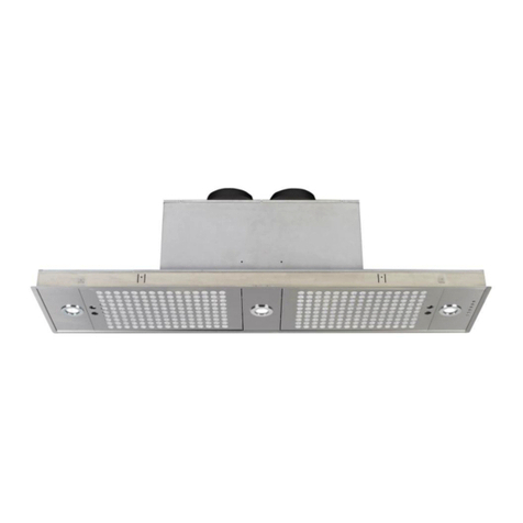
1 extractor hood (Complete with blower motor, lighting, mains supply cord and grease filter(s)
SECTION 2. EXTRACTION PERFORMANCE
The most important influence on the performance of the extractor is the design of the ducting which takes the exhaust air from the
extractor to the outside. The duct route should be a prime consideration during the initial stages of the kitchen design. Please note
the following:
The extractor is provided with a spigot(s) suitable for connecting 150mm diameter duct.
Note: 150mm is the minimum duct diameter consistent with efficient extraction.
Double blower (fan) models will require two independent duct runs.
The exhaust duct route length should be kept as short as possible with as few bends as possible.
The most efficient configuration is to duct straight through an outside wall so try to position the cooker against an outside wall
when designing your kitchen layout.
The hood is vented from the top exhaust. Use the position which gives the shortest duct route length and least number of bends.
A route with more than two 90 bends will significantly degrade the performance of the extraction system. Keep bend radii as
large as possible to maintain a smooth airflow without vortices; avoid kinks in flexible ducting; pull flexible ducting taut over
straight runs to ensure that the internal surface is as smooth as possible.
Rigid 150mm diameter (or equivalent rectangular) ducting should be considered for long or complex duct runs (which must be
sourced separately).
DO NOT REDUCE THE DUCTING DIAMETER OF 150MM AS THIS WILL REDUCE THE EXTRACTORS PERFORMANCE THIS
COULD RESULT IN DAMAGE TO THE MOTOR WHICH WOULD NOT BE COVERED BY WARRANTY.
SECTION 3. IMPORTANT INFORMATION
The following minimum headroom is required to accommodate the cooker and hood:
Cooker height (nominal):
900mm
Cooker-to-hood clearance
(min):
750mm
Cooker-to-hood clearance when
fitted with Lacanche Backsplash
850mm
Hood height Minimum
630 mm
Hood height Maximum
1050 mm
The minimum distance between the range hob burners and the bottom of the extractor is essential to prevent overheating of the
extractor and its components. When Fitting a Lacanche
Please also note that a 90 deg bend in the flexible ducting will require 215mm minimum headroom to give a smooth radius with
no kinking.
If ducting the FMPS100 extractor into a chimney it is recommended that the chimney must be lined and that the diameter of the
chimney must be a minimum of 150mm. Consideration must be give to the length of the chimney, a long chimney will reduce the
performance of the extractor.
The exhaust air must not be discharged into a flue which is used for exhausting fumes from appliances supplied with energy
other than electricity, e.g. oil or gas-fired central heating boilers, gas-fired water heaters, etc.
Requirements of the relevant authorities concerning the discharge of exhaust air must be complied with.
Adequate ventilation of the room must be provided when the cooker extractor and appliances supplied with energy other than
electricity (e.g. gas-fired or oil-fired heaters, etc.) are used simultaneously. The room must be provided with vents to allow a
constant flow of fresh air.
Attention: This appliance requires an earth connection
Ensure that the supply voltage corresponds to that marked on the rating label inside the extractor.
The extractor must be isolated from the electrical supply before carrying out any cleaning or maintenance operations.
If the power supply cable is damaged, it must be replaced by the manufacturer, its after-sales service, or a suitably qualified
person.
Pay particular attention to fire risk when frying. To minimise the risk of fire, all instructions relating to cleaning the grease filters
and removing grease deposits must be adhered to.
Do not flambé under the extractor.
The hood has been designed to remove the kitchen smells; any other additional use shall be regarded as non-intended.
This appliance is not intended for use by person (including children) with reduced physical, sensory, metal capabilities, or lack of
experience and knowledge, unless they have been given supervision or instruction concerning use of the appliance by a person
responsible for their safety.
This appliance is for domestic use only.

SECTION 4. INSTALLATION
Your Lacanche FMPS100 extraction hood is designed to be fitted directly onto a wall and is vented from the top. When installing
the extractor care should be taken on the position that the extractor is installed.
Before installing your extractor hood please remove the grease filters as per Fig.11.
By using the drilling Jig provided (Fig.5X) drill the wall according to the pattern indicated by the jig itself. Pay attention not to
damage water pipes and electrical cables which may be buried in the wall.
Use an 8mm dia drill bit to drill the fixing holes
Wall fixing plugs are provided with the hood Fig.5A. (Please insure that these fixings are suitable for the type of wall.) Insert the
wall fixing plugs into the drilled holes.
Position the hood mounting bracket (Fig.5S) over the fixings holes
Using the fixing screws (Fig.5B) secure the mounting bracket to the wall.
Ensure that the mounting bracket is securely fixed to the wall.
Using another person lift the and hang the hood onto the mounting bracket as per Fig.6.
With the hood in position adjust the horizontal and vertical screws as per Fig.7 till the hood is level

Fig 5 (X C A B S) Drilling Jig & Mounting Bracket Fixing Fig 6 Hanging the Hood on the Mounting
Bracket
Fig 7 Adjusting the Horizontal and Vertical Fixing Screws
Duct Installation
Make a hole or holes in the walls and/or ceiling, as necessary, in order to take 150mm diameter ducting from the extractor
spigot(s) to the outside.
The exhaust duct route length should be kept as short as possible with as few bends as possible.
If using FdeF duct kit ensure that holes in external wall will accommodate the ducting and connecting strap (Min 160mm
diameter).
Connecting the Ducting
Connect ducting to extractor exhaust spigot(s).
When the extractor is in position, check that the duct has not been flattened or kinked along its route.
Connect the ducting to the wall louver spigot or alternative outside termination.
Secure the louver to the outside wall. Ensure that the air fins are directed downwards.
Fig 8 Connecting Ducting to ducting spigot.
Warning
Do not reduce the ducting diameter from 150mm as this will affect the performance of the hood and could
damage the motor. Damage caused to the hood by incorrect ducting will not be covered by warranty.

Installing the Extractor Chimney Section
Using the centre line of the hood as guide fix the chimney mounting bracket to the ceiling or the wall as per Fig.9.
Connect the ducting as per Fig.8
Position the lower section of the chimney (as per Fig.10) onto the top of the extractor.
With the lower section of the chimney is position gently lifting the top section up to the chimney fixing bracket.
Secure the chimney to the fixing bracket using the screws provided.
Fig 9 Fixing the Chimney Mounting Bracket Fig 10 Positioning the Chimney

SECTION 5 REMOVING AND REFITING THE GREASE FILTERS
Remove the grease filters by pulling the latch out and then pulling the filter downwards as per Fig.11
To refit the grease filters ensure the tabs at the rear of the grease filter are located into the slots provided for on the extractor
see Fig.12.
With the catch in the open push the filter upwards towards the extractor till it can go no further then release the catch.
Fig 11 Removing the Grease Filter Fig 12 Refitting the Grease Filter

SECTION 6. ELECTRICAL INSTALLATION
ELECTRICAL HAZARD
DISCONNECT ELECTRICAL SUPPLY
BEFORE PROCEEDING FURTHER
The extractor is a stationary appliance designed to be connected by fixed wiring to the electrical supply. A competent electrical
technician must perform the electrical installation.
The hood must be fed from a 230Vac single phase electrical supply using a switched spur fitted with a 3A fuse for single
blower models or a 5A fuse for double blower models . The spur should be located adjacent to the hood/cooker so that the supply
can be disconnected from the hood using the switch. The means of disconnection from the supply must have a minimum contact
separation of 3mm in all poles. Alternatively, a means of disconnection in the fixed wiring according to the relevant wiring rules
must be fitted.
A supply cord for connecting the spur to the extractor is included.
The mains supply is connected to the free end of this cord as follows:
INCOMING SUPPLY CORD CONNECTIONS
Core
Core Colour
Live
Brown
Neutral
Blue
Protective Earth
Green/Yellow
SECTION 7. WARNING
Proper care must be taken to ensure that the negative pressures caused by high performance extraction systems do not
adversely affect the safe operation of certain types of fuel-burning appliances (gas, oil, or solid fuel), including those installed in
the kitchen and possibly also those installed in other parts of the house.
Where such fuel-burning appliances are installed, adequate ventilation MUST be provided in the room of installation, located, and
sized such that the negative pressure in the room created by the extractor does not exceed 4Pa.
In case of doubt, do not operate the extractor and fuel-burning appliance(s) simultaneously and consult an appropriate (for the
fuel type) expert for advice.
Should you require any further technical information please do not hesitate to call Fourneaux de France Ltd on:
01202 733011

SECTION 8. OPERATING INSTRUCTIONS
A. Light switch on/off
B. Reduce speed
C. Motor speed LED’s
D. Increase speed
E. 10 minute run on timer switch
Fig 13 Extractor Controls
If the push button console malfunctions, remove the grease filters and press the red button inside the appliance twice.
If the electrical power supply to the extractor is cut 15 seconds are needed for the self diagnostics to check the extractor after
the power is restored to the extractor.
Grease Filter alarm
After 30 hours of use the push buttons B & C (as per Fig.10) on the control panel will flash and signal saturation of the grease
filters. To reset the alarm press the timer button E. Please see section 9 for instruction on cleaning the grease filters
SECTION 8a Bi Power
The Bi Power function offers the customer the technical feature to make significant energy savings. The Bi Power function
enables the extractor to a have a 50% reduction of motor power and suction compared to the standard performance.
To enable the Bi Power function with the hood off keep pressing button D (Fig10)
LED’s L1 & L4 (Fig10) will flash for 5 seconds
The Bi Power function is now set
To return to full power
To return to full power with the extractor off keep pressing button D (Fig10)
LED’s L2 & L3 (Fig10) will flash for 5 seconds
The extractor is now at full power
SECTION 8b Auto Off
After 4 hours continues use the extractor will automatically switch off. To restart press button D (Fig.10)

SECTION 9. MAINTENANCE
WARNING
Unplug the appliance or switch off the circuit breaker before carrying out maintenance operations.
Regular maintenance is essential to ensure good performance and long-life.
To clean the stainless steel surfaces of the hood use a damp cloth only. Do not use abrasive cleaning materials or products on
any surface.
Clean the grease filters in a dishwasher or by hand-washing in hot water and detergent and allow to dry before refitting the filter
into the extractor. Wash the filters at least once a month - sooner if the extractor is used extensively
To maintain the immaculate appearance of the extractor, and to minimise fire risk, ensure that grease deposits on the extractor
surfaces are kept to a minimum by regular cleaning.
Replacing the Halogen lamps
To replace the halogen lamp locate the inner ring of the light frame as per Fig.14
Insert a small flat blade screw driver into the inner ring slot and gently easy the inner ring and glass lens away from the outer
frame as per Fig.15.
With the inner ring and glass cover removed, gently pull the lamp away from the light.
Replace the bulb with the same rated type bulb 20w 12 volt halogen. Do not handle the halogen lamp without a cloth as contact
with human skin reduces the life of the lamp.
Refit the inner ring and glass cover by
Fig 14 Light frame Fig 15 Light frame open
Inner ring & Inner ring slot

SECTION 10. CONSTRUCTION AND TECHNICAL SPECIFICATIONS
4.1 CONSTRUCTION CHARACTERISTICS
- STAINLESS STEEL SHEET BODY Thickness 8/10
- ALUMINIUM BODY AISI - 430.
4.2 GENERAL CHARACTERISTICS
- ELECTRICAL SYSTEM ACCORDING TO THE INTERNATIONAL REGULATIONS
- 2 x 20W HALOGEN LIGHTING
- 4 OPERATING SPEEDS
- COOKING COUNTER LIGHTING SYSTEM
4.3 TECHNICAL DATA
- FLOW RATE PER HOUR MC 1000
- STATIC PRESSURE 400 Pa
- MOTOR ABSORPTION 265w
- SUPPLY VOLTAGE:
220-240V / 50-60HZ
- WEIGHT KG 23
The symbol on the product or on its packaging indicates that this product may not be treated as household waste. Instead it shall be handed
over to the applicable collection point for the recycling of electrical and electronic equipment. By ensuring this product is disposed of correctly,
you will help prevent potential negative consequences for the environment and human health, which could otherwise be caused by inappropriate
waste handling of this product. For more detailed information about recycling of this product, please contact your local city office, your household
waste disposal service or the shop where you purchased the product. This appliance is marked according to the European directive 2002/96/EC on
waste electrical and electronic equipment (WEEE).

Table of contents
Other Lacanche Range manuals

Lacanche
Lacanche RULLY Configuration guide

Lacanche
Lacanche CLUNY User manual

Lacanche
Lacanche BEAUNE User manual

Lacanche
Lacanche CHAGNY User manual

Lacanche
Lacanche Sully User guide

Lacanche
Lacanche BFU TWIN Operation instructions

Lacanche
Lacanche Vougeot - Volnay Configuration guide

Lacanche
Lacanche Fourneau Cormatin User guide

Lacanche
Lacanche BUSSY User manual

Lacanche
Lacanche Bienvenue User manual
Popular Range manuals by other brands

Kenmore
Kenmore 790.9659 Use & care guide

KitchenAid
KitchenAid KDRP407HSS - 30" Pro-Style Dual-Fuel Range installation instructions

Frigidaire
Frigidaire FGGF3030P Brochure & specs

Whirlpool
Whirlpool SE960PEYN1 Use & care guide

Cannon
Cannon TRADITIONAL 60 owner's manual

Maytag
Maytag CRE9900ACB owner's manual