3700 Sagamore Parkway North . Lafayette, IN 47904 USA . Phone: (765) 423-1505
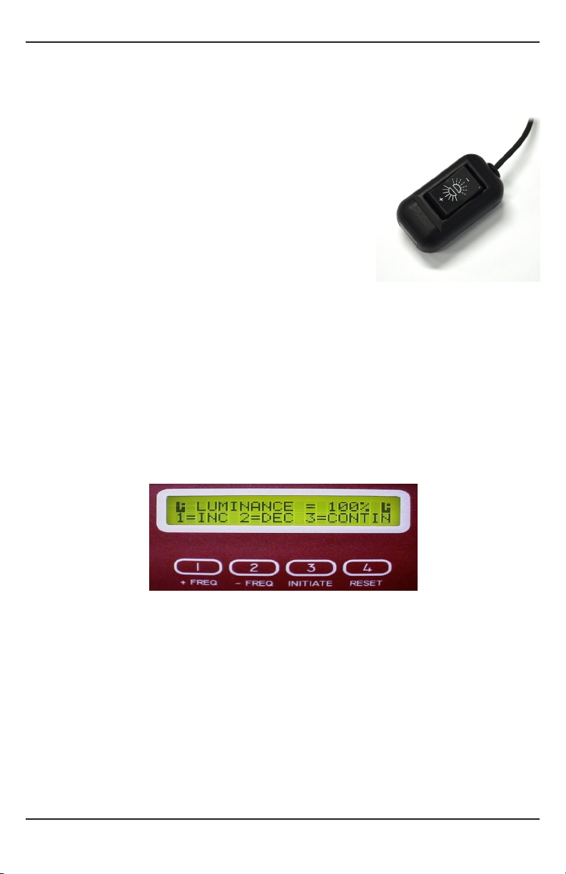
Lafayette Instrument Flicker Fusion
Terms and Conditions
LIC Worldwide Headquarters
Toll-Free: (800) 428-7545 (USA only)
Phone: (765) 423-1505
Fax: (765) 423-4111
Mailing Address:
Lafayette Instrument Company
PO Box 5729
Lafayette, IN 47903, USA
Lafayette Instrument Europe:
Phone: +44 1509 817700
Fax: +44 1509 817701
Phone, Fax, Email or Mail-in Orders
All orders need to be accompanied by a hard copy of your purchase order. All
orders must include the following information:
• Quantity
• Part Number
• Description
• Your purchase order number or method of pre-payment
• Your tax status (include tax-exempt numbers)
• Shipping address for this order
• Billing address for the invoice we’ll mail when this order is shipped
• Signature and typed name of person authorized to order these
products
• Your telephone number
• Your email address
• Your FAX number
Domestic Terms
There is a $50 minimum order. Open accounts can be extended to most
recognized businesses. Net amount due 30 days from the date of shipment
unless otherwise specied by us. Enclose payment with the order; charge with
VISA, MasterCard, American Express, or pay COD. We must have a hard copy
of your purchase order by mail, E-mail or fax. Students, individuals and private
companies may call for a credit application.
International Payment Information
There is a $50 minimum order. Payment must be made in advance by: draft
drawn on a major US bank; wire transfers to our account; charge with VISA,
MasterCard, American Express, or confirmed irrevocable letter of credit.
Proforma invoices will be provided upon request.
Exports
If ordering instrumentation for use outside the USA, please specify the country
of ultimate destination, as well as the power requirements (110V/60Hz or
220V/50Hz). Some model numbers for 220V/50Hz will have a “*C” sux.
Quotations
Quotations are supplied upon request. Written quotations will include the price
of goods, cost of shipping and handling, if requested, and estimated delivery
time frame. Quotations are good for 30 days, unless otherwise noted. Following
that time, prices are subject to change and will be re-quoted at your request.
Cancellations
Orders for custom products, custom assemblies or instruments built to customer
specications will be subject to a cancellation penalty of 100%. Payment for up
to 100% of the invoice value of custom products may be required in advance.
Cancellation for a standard Lafayette Instrument manufactured product once
the product has been shipped will normally be assessed a charge of 25% of the
invoice value, plus shipping charges. Resell items, like custom products, will be
subject to a cancellation penalty of 100%.
Exchanges and Refunds
Please see the cancellation penalty as described above. No item may be returned
without prior authorization of Lafayette Instrument Company and a completed
Return Form. A copy of the Return Form or your assigned Return # (you will
receive this via email after submitting the form) must be included with the
returned goods. The merchandise should be packed well and fully insured.
Unopened merchandise may be returned prepaid within thirty (30) days after
receipt of the item and in the original shipping carton. Collect shipments will
not be accepted. Returned products must be in saleable condition, and credit
is subject to inspection of the merchandise.
Repairs
Instrumentation may not be returned without prior authorization by
Lafayette Instrument Company and a completed Return Form. When you
complete the Form, or call Lafayette Instrument, you will receive a Return
#. Your Return # number will be good for 30 days. Address the shipment to:
Lafayette Instrument Company
3700 Sagamore Parkway North
Lafayette, IN 47904, USA.
Shipments cannot be received at the LIC PO Box. Items should be packed well,
insured for full value, and returned along with a copy of the Return Form or
the Return #. An estimate of repair will be given prior to completion ONLY if
requested in an enclosed cover letter. We must have a completed purchase
order by mail or fax, or repair work cannot commence for non-warranty repairs.
Damaged Goods
Damaged instrumentation should not be returned to Lafayette Instrument
prior to a thorough inspection. If a shipment arrives damaged, note damage on
delivery bill and have the driver sign it to acknowledge the damage. Contact the
delivery service, and they will le an insurance claim. If damage is not detected at
the time of delivery, contact the carrier/shipper and request an inspection within
10 days of the original delivery. Please call the Lafayette Instrument Customer
Service Department for repair or replacement of the damaged merchandise.
Limited Warranty
Lafayette Instrument Company warrants equipment manufactured by the
company to be free of defects in material and workmanship for a period of one
year from the date of shipment, except as provided hereinafter. The original
manufacturer’s warranty will be honored by Lafayette Instrument for items not
manufactured by Lafayette Instrument Company, i.e. resell items. This assumes
normal usage under commonly accepted operating parameters and excludes
consumable products.
Warranty period for repairs or used instrumentation purchased from Lafayette
Instrument is 90 days. Lafayette Instrument Company agrees either to
repair or replace, at its sole option and free of part charges to the customer,
instrumentation which, under proper and normal conditions of use, proves to
be defective within the warranty period. Warranty for any parts of such repaired
or replaced instrumentation shall be covered under the same limited warranty
and shall have a warranty period of 90 days from the date of shipment or the
remainder of the original warranty period whichever is greater. This warranty
and remedy are given expressly and in lieu of all other warranties, expressed or
implied, of merchantability or tness for a particular purpose and constitutes
the only warranty made by Lafayette Instrument Company.
Lafayette Instrument Company neither assumes nor authorizes any person to
assume for it any other liability in connection with the sale, installation, service or
use of its instrumentation. Lafayette Instrument Company shall have no liability
whatsoever for special, consequential, or punitive damages of any kind from any
cause arising out of the sale, installation, service or use of its instrumentation.
All products manufactured by Lafayette Instrument Company are tested and
inspected prior to shipment. Upon prompt notification by the Customer,
Lafayette Instrument Company will correct any defect in warranted equipment
of its manufacture either, at its option, by return of the item to the factory, or
shipment of a repaired or replacement part. Lafayette Instrument Company
will not be obliged, however, to replace or repair any piece of equipment,
which has been abused, improperly installed, altered, damaged, or repaired by
others. Defects in equipment do not include decomposition, wear, or damage by
chemical action or corrosion, or damage incurred during shipment.
Limited Obligations Covered by this Warranty
1. In the case of instruments not of Lafayette Instrument Company
manufacture, the original manufacturer’s warranty applies.
2. Shipping charges under warranty are covered only in one direction.The
customer is responsible for shipping charges to the factory if return of
the part is required.
3. This warranty does not cover damage to components due to improper
installation by the customer.
4. Consumable and or expendable items, including but not limited to
electrodes, lights, batteries, fuses, O-rings, gaskets, and tubing, are
excluded from warranty.
7. Failure by the customer to perform normal and reasonable maintenance
on instruments will void warranty claims.
8. If the original invoice for the instrument is issued to a company that
is not the company of the end user, and not an authorized Lafayette
Instrument Company distributor, then all requests for warranty must
be processed through the company that sold the product to the end
user, and not directly to Lafayette Instrument Company.
Export License
The U.S. Department of Commerce requires an export license for any polygraph
system shipment with an ULTIMATE destination other than: Australia, Japan,
New Zealand or any NATO Member Countries. It is against U.S. law to ship a
Polygraph system to any other country without an export license. If the ultimate
destination is not one of the above listed countries, contact us for the required
license application forms.