manuals.online logo
Brands
  1. Home
  2. •
  3. Brands
  4. •
  5. Lake Shore Cryotronics
  6. •
  7. Thermometer
  8. •
  9. Lake Shore Cryotronics PT-102 User manual

Lake Shore Cryotronics PT-102 User manual

Instructions,
Platinum Resistance Thermometer Installation
Lake Shore Cryotronics, 575 McCorkle Blvd. Westerville, OH 43082 www.lakeshore.com
Phone (614) 891-2243 – Fax (614) 891-1362 – sales@lakeshore.com – service@lakeshore.com
Model PT-102, PT-103, and PT-111
The PT-102, PT-103, and PT-111 are wire-wound thermometers and normally used as
secondary standards. However, these thermometers should be treated in the same manner
as any precision instrument. It is recommended that they not be subjected to any
unnecessary shock or rough mechanical treatment.
In reading the thermometer, it is important to use the proper measuring current. An excessively
high current will cause joule heating (I2R), thus giving erroneous reading. Lake Shore
recommends a maximum power dissipation (joule heating) of 10 µW: the same as used in
calibration. The recommended measuring currents to avoid joule heating are as follows:
0 Ωto 200 Ω0.5 mA
200 Ωto 1200 Ω0.1 mA
There are three aspects of using a cryogenic temperature sensor which are critical to its optimum performance: 1) proper
mounting of the sensor package, 2) proper joining of sensor lead wires and connecting wires, and 3) proper thermal anchoring
of the connecting wires. Although the sequence in which these concerns should be addressed is not fixed, all elements
covered under each aspect should be adhered to for maximum operating capabilities of the sensor.
MOUNTING ADAPTERS
PT-102-AL and PT-103-AM each include a platinum RTD sensor mounted into a flat aluminum block. They can be mounted to
any flat surface with a 6-32 or M3 screw (not included) and Inconel® Belleville washer (included).
Adapter material: 6061 Al block (PT mounted to adapter using Cotronics Durabond® 950 Al-based adhesive)
AL leads: Two 0.010-inch diameter: 10.160 ±1.270 mm (0.400 ±0.050 in) long
AM leads: Two 0.010-inch diameter: 15.240 ±1.270 mm (0.600 ±0.050 in) long
Lead material: Platinum
Mass: PT-102-AL: 3.8 g, PT-103-AM: 2.1 g
Limitation: The aluminum alloy limits the upper useful temperature of these configurations to 800 K
PT-102-AL PT-103-AM
Form Number F022-00-00 Revision F — ©2017 Lake Shore Cryotronics, Inc. — 2 May 2017 — Page 2
SENSOR MOUNTING
1. Mounting area should be prepared and cleaned with a
solvent such as acetone followed by an isopropyl
alcohol rinse. Allow time for the solvents to evaporate
before sensor mounting. Follow manufacturer’s
instructions for mixing and curing adhesives. Carefully
note temperature range limitations of the greases,
varnishes, and epoxies to be used.
2. The list below provides brief instructions on mounting
a sensor using a number of different methods. The
constraints of your application should dictate the most
appropriate mounting method to follow.
Apiezon®N Grease — Best used as a thermal
conductor for temperatures under room temperature
when the sensor is mounted in a hole or recess and
when the sensor needs to be removable. The sensor
should be surrounded with thermal grease and placed
into the mounting position. When the temperature is
lowered the thermal grease will harden, giving good
support and thermal contact. NOTE: Use Apiezon®H
grease for high temperature applications up to 500 K.
The use of grease is not recommended for use in high
temperature applications above 500 K.
IMI 7031 Varnish — Prepare varnish and apply a thin
layer on the mounting surface. Press the sensor firmly
against the varnish during curing to ensure a thin
bond layer and good thermal contact. Varnish will air
dry in 5 to 10 min. Sufficient time must be allowed for
the solvents in the varnish to evaporate.
There is a small probability of ionic shunting across
the sensor during the cure period of the varnish
(typically 12 to 24 h).
Stycast ® 2850FT Epoxy — Prepare epoxy and apply
a thin layer on the mounting surface. Press the sensor
firmly into the epoxy during curing to ensure a thin
bond layer and good thermal contact. Epoxy will cure
in 12 h at 25 °C or in 2 h at 66 °C.
NOTE: Varnish, epoxies, and other adhesives should
be considered permanent mounts and only be used if
the sensor is not intended for removal.
Aluminum mounting adapter — The sensor has been
mounted to this adapter using Cotronics’ Durabond™
950 aluminum-based adhesive. This adhesive is well
matched to the temperature expansion coefficient of
the aluminum adapter. Attach the sensor adapter
using a 6-32 or M3 screw along with an Inconel®
Belleville washer. The washer is provided. Do not
over tighten the screw. The Belleville washer should
not be flattened.
3. Follow manufacturers’ instructions for adhesive curing
schedules. Carefully note the temperature range of
use for greases, varnishes, and epoxies. Grease is
not recommended to fill voids when the sensor will be
used above 500 K.
Instructions,
Platinum Resistance Thermometer Installation
Form Number F022-00-00 Revision F — ©2017 Lake Shore Cryotronics, Inc. — 2 May 2017 — Page 3
LEAD ATTACHMENT
1. Although the platinum sensors are 2-lead devices,
measurements should preferably be made using a
4-wire configuration to avoid uncertainties associated
with the resistance of the connecting leads.
2-Lead Measurement Scheme — The leads used to
measure the voltage are also the current carrying
leads. The resulting voltage measured at the
instrument is the sum of the temperature sensor
voltage and the voltage drop across the two
connecting leads. (See Figure 1A.)
4-Lead Measurement Scheme — The current is
confined to one pair of current leads with the sensor
voltage measured across the voltage leads. (See
Figure 1B.)
2. Lead Polarity: None.
3. For use up to 500 K, phosphor bronze or Manganin®
wire in 32 or 36 AWG is commonly used as the
connecting lead wire. These wires have low thermal
conductivity and high resistivity, which helps minimize
the heat flow through the leads. Typical wire
insulation is polyvinyl formal (Formvar®) or polyimide
(ML). Formvar insulation has better mechanical
properties such as abrasion resistance and flexibility.
Polyimide insulation has better resistance to chemical
solvents and burnout. Formvar has a temperature
rating of 373 K while polyimide has a temperature
rating of 505 K.
4. For use above 500 K, use high temperature
connecting wire (e.g., nickel) with high temperature
insulation (e.g., wrap-around, ceramic tube, or
ceramic beaded). Connection should be made by spot
welding or brazing.
5. Platinum sensor leads can easily be soldered if a flux
is used. One suitable flux is Stay Clean®Solder and
Tinning Flux (J.W. Harris Company, Cincinnati, Ohio).
Use appropriate solder with respect to temperature
(recommend Sn 60/Pb 40 for up to 400 K and
Pb 90/Sn 10 for up to 500 K.)
6. Stay Clean®Solder and Tinning Flux is acidic. Hence,
after soldering, clean off the residual flux with a
solvent that is “basic” in nature (i.e., baking soda
dissolved in water will also work).
7. Join one sensor lead with two of the connector wires.
Apply the soldering iron to the connector wire above
the joint area until the solders melt, then remove the
iron. Repeat for the other set of connector wires and
the other sensor lead.
8. Avoid putting stress on the device leads and leave
enough slack to allow for the thermal contractions that
occur during cooling, which could fracture a solder
joint or lead. Some epoxies and shrink tubing can put
enough stress on lead wires to break them.
9. If the sensor is to be used above 500 K, it is
recommended to either braze or spot weld
appropriate lead wires (e.g., nickel wire).
Instructions,
Platinum Resistance Thermometer Installation
Form Number F022-00-00 Revision F — ©2017 Lake Shore Cryotronics, Inc. — 2 May 2017 — Page 4
HEAT SINKING/THERMAL ANCHORING
1. Since the area being measured is read through the
body of the sensor, heat flow through the connecting
leads can create an offset between the sensor and
the true sample temperature. Thermal anchoring of
the connecting wires is necessary to ensure that the
sensor and the leads are at the same temperature as
the sample.
2. Connecting wires should be thermally anchored at
several temperatures between room temperature and
cryogenic temperatures to guarantee that heat is not
being conducted through the leads to the sensor.
Two different sizes of copper bobbins are available
from Lake Shore for heat sinking connecting leads:
P/N 9007-900 (large) and 9007-901 (small).
3. If connecting wires have a thin insulation such as
Formvar or polyimide, a simple thermal anchor can be
made by winding the wires around a copper post,
bobbin, or other thermal mass. A minimum of five
wraps around the thermal mass should provide
sufficient thermal anchoring. However, if space
permits, additional wraps are recommended for good
measure. To maintain good electrical isolation over
many thermal cycles, it is good practice to first varnish
a single layer of cigarette paper to the anchored area,
and then wrap the wire around the paper and bond in
place with a thin layer of IMI 7031 varnish. Formvar
wiring insulation has a tendency to craze with the
application of IMI varnish. If used, the wires cannot be
disturbed until the varnish is fully cured and all
solvents have evaporated (typically 12 to 24 h).
4. A final thermal anchor at the sample itself is good
practice to ensure thermal equilibrium between the
sample and temperature sensor.
CALIBRATED SENSORS
As a 2-lead device, the resistance of a platinum sensor’s
leads is included in the measured resistance during
calibration. Cutting the leads to a shorter length, tinning a
greater portion of the lead length with solder, or otherwise
changing the point of lead attachment will affect the overall
measurement even if a 4-lead measurement is made to
the point of connection with the sensor leads. Additionally,
the lead material is not pure platinum, but rather an alloy
or coated wire used to increase solderability and provide a
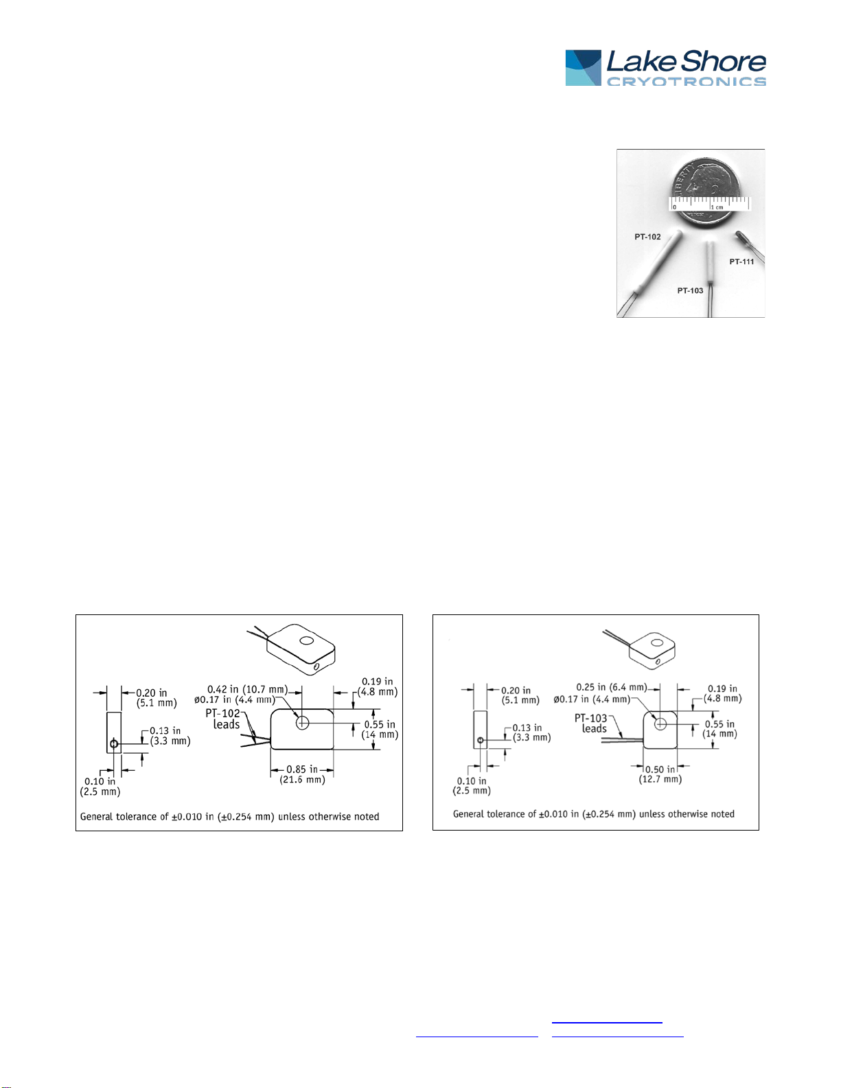
more robust lead. The lead material is Pt-Rh (5%) alloy
wire for the PT-103, platinum-coated palladium wire for the
PT-102, and platinum-coated nickel wire for the PT-111.
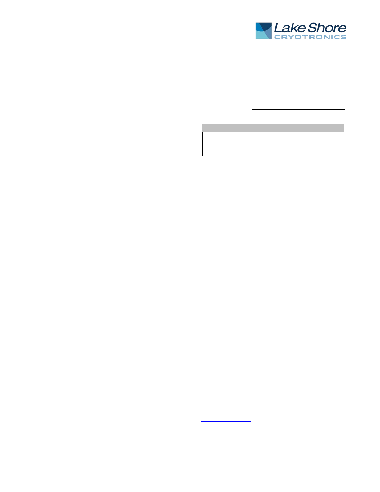
During calibration at Lake Shore, contact to each lead is
made within 1 mm of the lead end. An estimate of the
calibration shift for each 1 mm lead length change is given
below for each of the three models. For the PT-103 sensor
(which shows a relatively significant lead error below
30 K), the two sensor leads are branched into four leads
prior to calibration, and the sensor is delivered with the
four leads attached. The extensions are bare nickel wire
brazed to the sensor leads using Fusion Inc. LHK-1235-
701 silver brazing paste.
Calibration shift (mK) per 1 mm
lead length change
Temperature (K)
PT-102 or PT-111
PT-103
295
8.9
9.5
77
2.1
5.4
20
0.5
24
CRYOGENIC ACCESSORIES — Recommended for
proper installation and use of platinum sensors
Stycast®Epoxy 2850FT (P/N 9003-020, 9003-021):
Permanent attachment, excellent low temperature
properties, poor electrical conductor, low cure shrinkage.
Apiezon®N Grease (P/N 9004-020): Low viscosity, easy
to use, solidifies at cryogenic temperatures, excellent
lubricant.
IMI 7031 Varnish (P/N 9009-002): Nonpermanent
attachment, excellent thermal conductor, easy to apply
and remove.
Indium Solder (P/N 9007-002-05): 99.99% pure, excellent
electroplating material, foil form.
90% Pb 10% Sn Solder (P/N 9008-001): Greater lead
content for higher temperature applications no greater
than 200 °C.
Phosphor Bronze Wire (P/N 9001-00X): Available in
single, duo, and quad strands, no magnetic attraction, low
thermal conduction.
Manganin®Wire (P/N 9001-00X): Low thermal
conductivity, high resistivity, no magnetic attraction.
Heat Sink Bobbin (P/N 9007-900 large, 9007-901 small):
Gold-plated oxygen-free high-conductivity (OFHC) copper
bobbins.
Instruments: Lake Shore sells a complete line of
instrumentation for use with platinum sensors, including
current sources, cryopump monitors, temperature
controllers, monitors and thermometers, temperature
scanners and transmitters.
For complete product description and detailed
specifications on the above accessories and instruments,
consult the Lake Shore Temperature Measurement and
Control Catalog, call (614) 891-2243, e-mail
sales@lakeshore.com, or visit our website at
www.lakeshore.com.

This manual suits for next models

2

Popular Thermometer manuals by other brands

Beurer FT 90 instruction manual

Beurer

Beurer FT 90 instruction manual

RayTek MX4TD manual

RayTek

RayTek MX4TD manual

Welch Allyn Braun ThermoScan PRO 6000 Directions for use

Welch Allyn

Welch Allyn Braun ThermoScan PRO 6000 Directions for use

TESTO 105 instruction manual

TESTO

TESTO 105 instruction manual

JENCO 701 Operation manual

JENCO

JENCO 701 Operation manual

Oregon Scientific RAR232 user manual

Oregon Scientific

Oregon Scientific RAR232 user manual

Gima 25585 Use and maintenance book

Gima

Gima 25585 Use and maintenance book

BioMax BM-TDA user manual

BioMax

BioMax BM-TDA user manual

Philips AVENT SCH550 manual

Philips

Philips AVENT SCH550 manual

Welch Allyn 767 Technical manual

Welch Allyn

Welch Allyn 767 Technical manual

Levenhuk WEZZER COOK MT50 user manual

Levenhuk

Levenhuk WEZZER COOK MT50 user manual

Extech Instruments RH101 user guide

Extech Instruments

Extech Instruments RH101 user guide

Hanna Instruments HI 9271 instruction manual

Hanna Instruments

Hanna Instruments HI 9271 instruction manual

WIKA IntelliTHERM TGT73 operating instructions

WIKA

WIKA IntelliTHERM TGT73 operating instructions

Maverick ET-77 instruction manual

Maverick

Maverick ET-77 instruction manual

FLIR Extech VIR50 user manual

FLIR

FLIR Extech VIR50 user manual

scigiene RHT-Air instruction manual

scigiene

scigiene RHT-Air instruction manual

COMED FR1DZ1 user manual

COMED

COMED FR1DZ1 user manual

manuals.online logo
manuals.online logoBrands
  • About & Mission
  • Contact us
  • Privacy Policy
  • Terms and Conditions

Copyright 2025 Manuals.Online. All Rights Reserved.