INSTNo.INE-459-0P2CE Ver.1.11
-C3-
CONTENTS
1. Introduction··················································1
1.1 General························································1
2. Model and accessories ·································1
2.1 Model··························································1
2.2 Accessories ·················································1
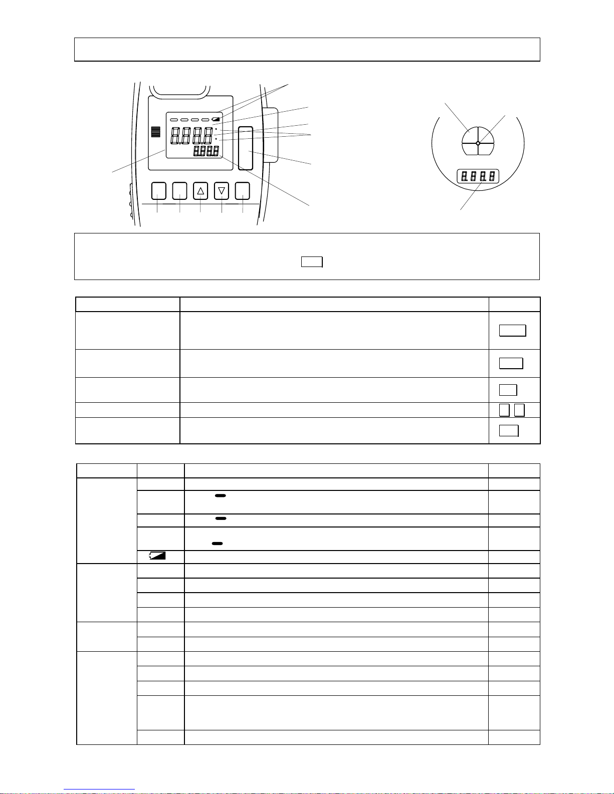
3. Names and functions of
component parts··························2
3.1 Views ··························································2
3.2 Functions ····················································2
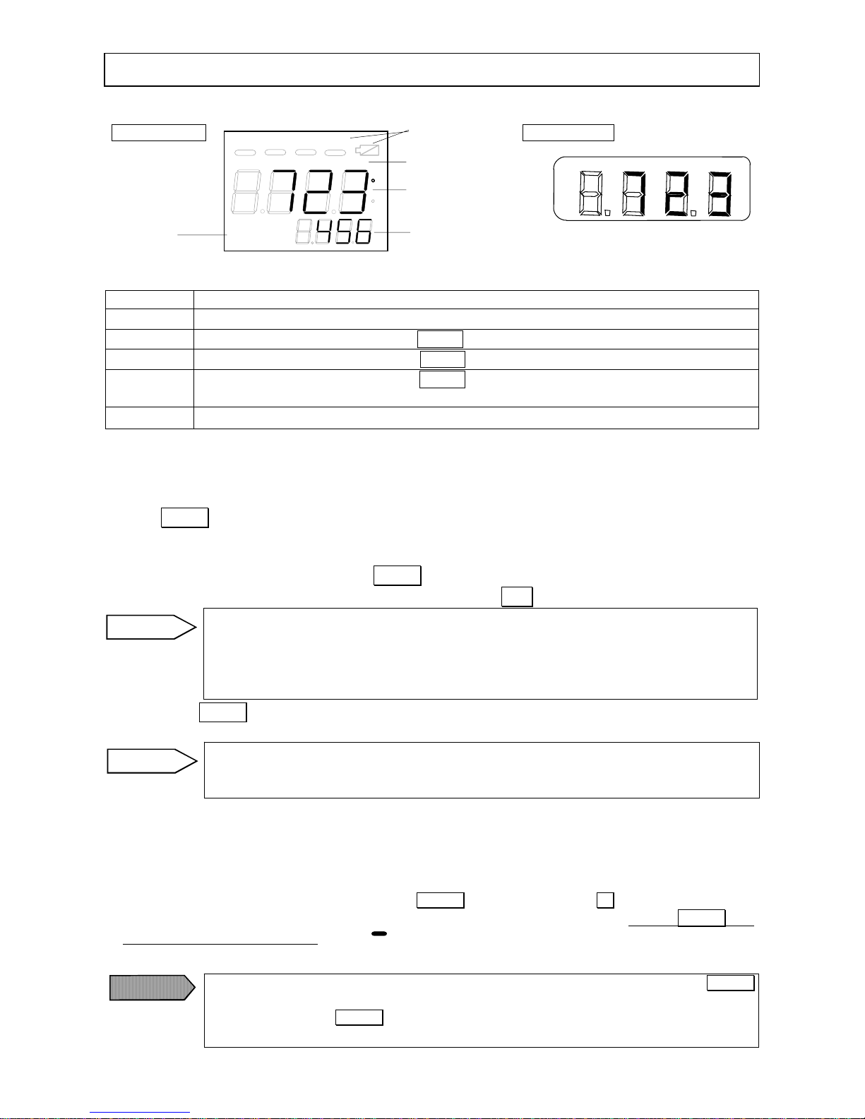
3.3 External Display ·········································3
3.4 Viewfinder ··················································3
3.5 Functions of keys········································3
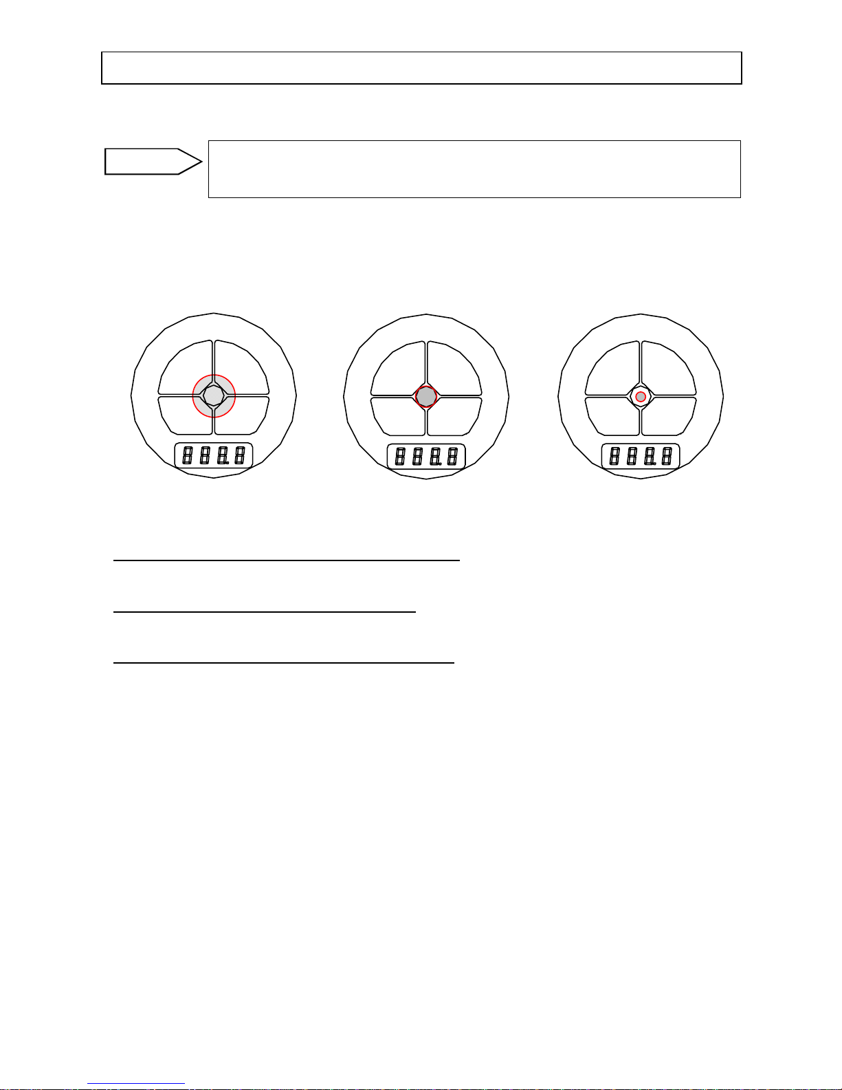
3.6 Markers·······················································3
4. Preparation for measurement·····················4
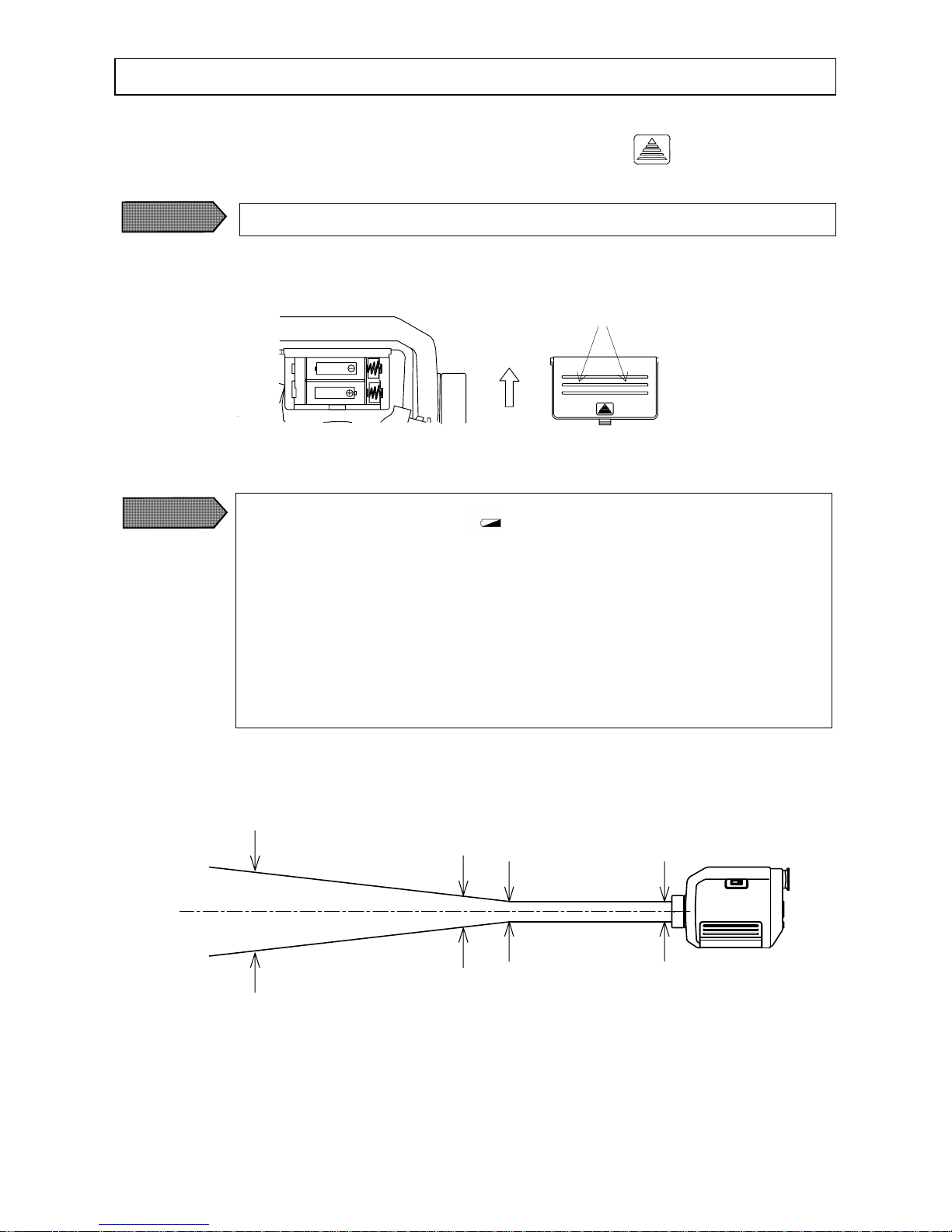
4.1 Loading batteries·········································4
4.2 Distance and diameter·································4
4.3 Targeting·····················································5
5. Measuring·····················································6
5.1 Standard measurement mode ······················6
5.2 Continuous measurement mode ··················6
5.2.1 Start of continuous measurement ·············6
5.2.2 Cancellation of continuous
measurement···········································7
5.3 Caution on measurement·····························7
5.4 Emissivity rate setting·································8
5.5 Measurement mode selections ····················8
5.5.1 Signal modulation mode selection············8
5.5.2 Temperature unit selection ·······················9
5.5.3 2-color type/single color type selection··10
5.6 Measurement mode settings······················10
5.6.1 Low temperature alarm setting···············10
5.6.2 High temperature alarm setting··············11
5.6.3 Modulation value setting························11
5.6.3-1) Modulation time constant setting
(for “dLEy” selected)·····11
5.6.3-2) Damping degree setting
(for “PEAk” selected)·····11
6. Temperature data storage·······················12
6.1 Data storage mode ································· 12
6.2 Data storage number setting and
recalling of stored data········· 14
6.2.1 Data storage number setting················ 14
6.2.2 Recalling of stored data ······················ 15
6.3 Memory full··········································· 16
6.4 Erasing all stored data···························· 16
7. Maintenance and check··························17
7.1 Self-diagnostic function························· 17
7.2 Storage··················································· 17
7.3 Cleaning of objective lens······················ 17
7.4 Cleaning of external display and
eyepiece cover······ 17
8. List of starting up modes························18
8.1 Modes at start up···································· 18
8.2 Table of screens ····································· 18
8.3 Measurement mode settings/display ······ 18
8.3.1 Emissivity rate setting/ display ··········· 18
8.3.2 Data storage number setting/ display ·· 18
8.4 System settings ······································ 18
9. General specifications·····························19
9.1 Specifications········································· 19
9.2 Outside dimensions································ 19
Note: Make sure to read the items with the
markof
The articles of are included.
Software Ver. 1.11