
Operating Instructions
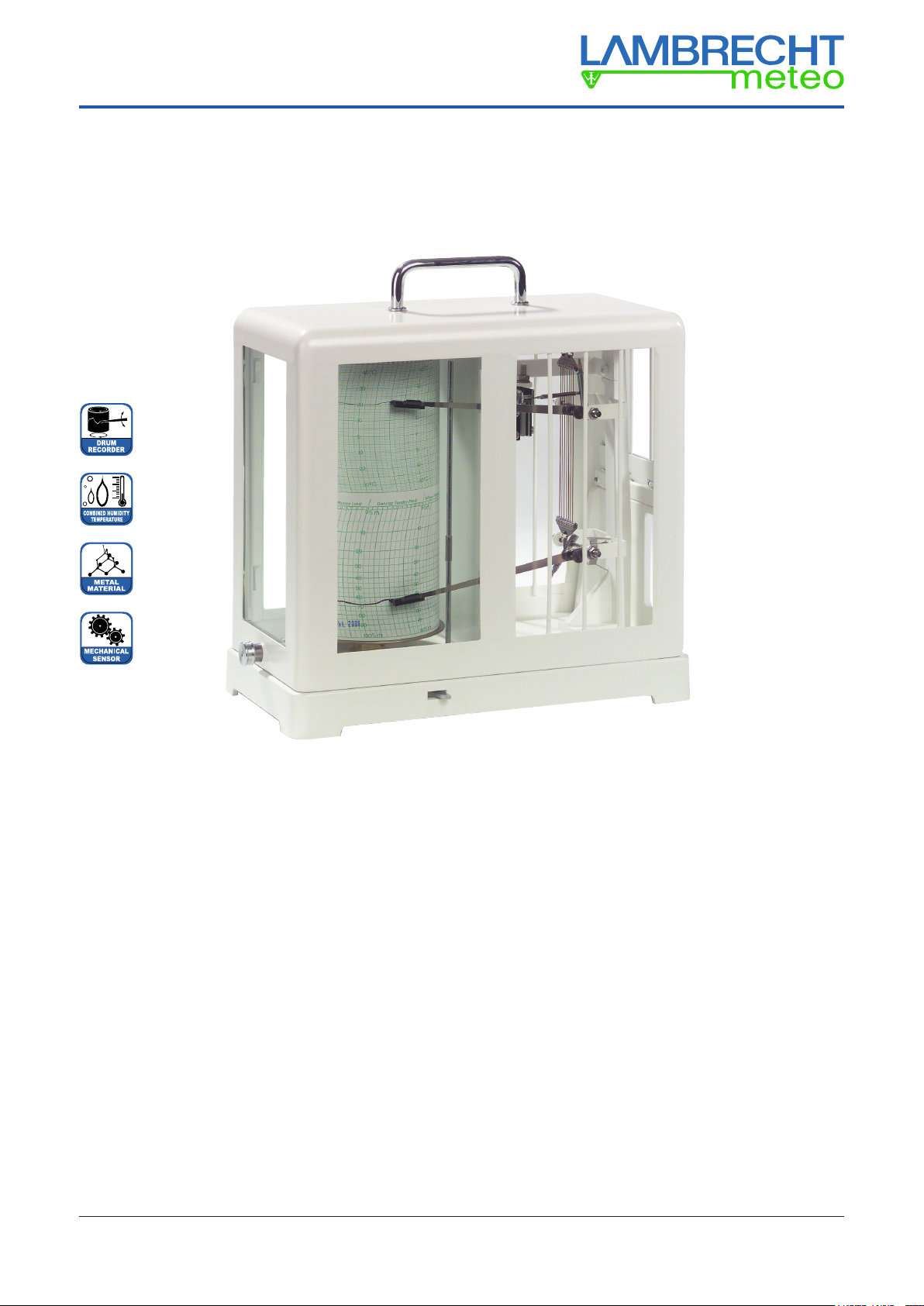
Thermo-Hygrograph (252)
Enclosure: Operating Instructions “Drum Recorders“
Thermo-Hygrograph (252) OperatingInstructions
3.3 Inserting the battery
(quartz clockworks only)
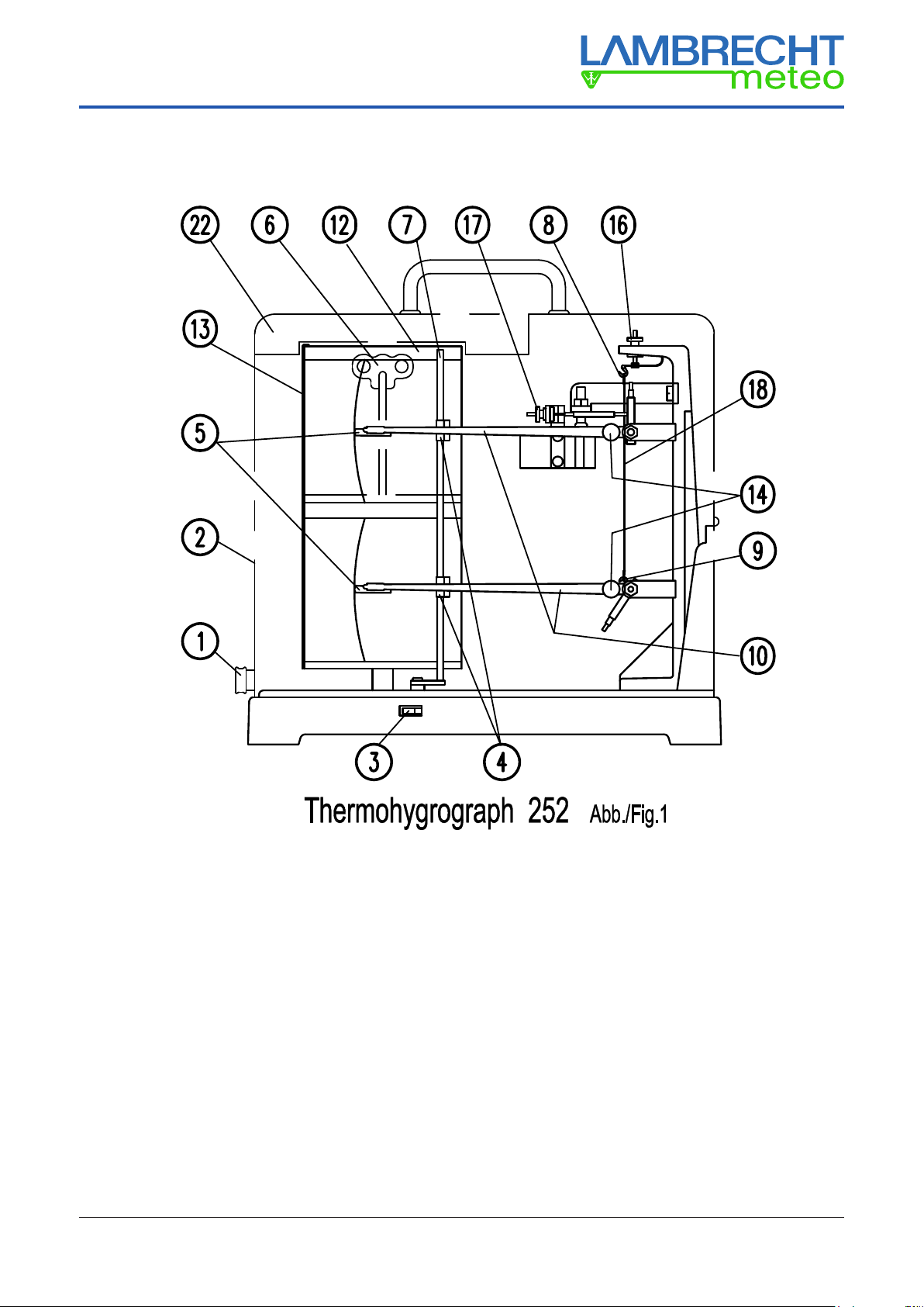
Lift the recording arms using the switch-o lever 3. Pull o the
drum 12 straight and very carefully, making sure not to bend
it sideways. Then push aside the yoke spring and check the
polarity when inserting the battery (1.5 V, type Mignon/AA).
Adjust the desired recording period at the gear wheels. Then
remount everything carefully (don’t bend the recording arms).
3.4 Winding up the clockwork
(mechanical clockworks only)
The moving spring is stretched by turning the winding key 6
anti-clockwise.
3.5 Setting the drum to local time
The felt-tipped pens must be very close to the paper surface
(adjusted by using the switch-o lever 3). Turn the drum 12
counterclockwise until the pen matches the desired time line.
If you have turned the drum too far, turn it back beyond the
desired time line so that you can resume the adjustment from
the beginning. This way the backlash of the toothed gears will
be eliminated. Since a graph paper has been already inserted
in the factory, the instrument is ready for operation after closing
the hood. Attention: You must hear locking knob 1 clicking in
place! After taking the device to the desired place of instal-
lation, you can put the felt-tipped pen into writing position by
turning the switch-o lever 3.
3.6 Change of the recording period of me-
chanically reversible clockworks (Fig. 3)
When delivered, the recording period is 7 days.
In order to change the recording period to 1 day, open the
instrument’s housing 2, unscrew the winding key 6clockwise
and pull the drum completely o the axis.
The gear wheel in the lower part of the drum has to be pulled
off and is re-inserted vice versa. Afterwards re-assemble
everything.
4.0 Service and maintenance
4.1 Changing graph paper
Using the switch-o lever 3, take the pen o the paper. Loosen
the metal clasp 13 on the clockwork drum by pushing it up.
Remove the old graph paper and put on a new one. Both chart
ends must be below the metal clasp; the lower edge of the
chart must t evenly to the lower edge of the clockwork drum.
Rex the metal clasp. Set the time as described under 3.5.
4.2 Changing the felt-tipped pens
Carefully pull the used felt-tipped pen 5 from the recording arm
and attach a new pen. Remove the protective cap and save it.
4.3 Felt-tipped pen contact pressure
To adjust the correct contact pressure, rst put the recording
arm into writing position using the switch-o lever 3. Tilt the
device by about 30° to the front. If the felt-tipped pens are
adjusted correctly, they should now be 1...2 mm from the chart
surface. You may have to turn the screws 14 to set the tips to
the correct distance. Too much pressure (thick recording line)
generates too much friction between the felt-tipped pens and
the graph paper, leading to wrong measuring results. If the
pressure is too weak (thin recording line) there is a risk that
the recording will be interrupted.
4.4 Cleaning and care
The bearings should not be oiled. Every three to ve years,
mechanical clockworks should be maintained by a clock mak-
er. The rest of the device may be carefully cleaned, using a
soft brush or a damp cloth.
4.5 Putting out of service
If the device is temporarily put out of service, the felt-tipped
pens must be covered with the supplied caps to prevent them
from drying out.
4.6 Transport
Use the switch-o lever 3 to lift the recording arms and secure
them with the cardboard wedge (see 2.1); put the protective
caps onto the felt-tipped pens. The recording arm 10 of
the humidity measuring element must be secured with the
transport lock 4 so that the measuring element is unstressed
(recording arm tip at approx. 20% r.h.). For dispatch the hu-
midity measuring element (except the humidity measuring ele-
ment K) must be unhooked and put into the original ip pack.
During transport the quartz clockwork 15 should not be in
operation.
5.0 Clockworks (gear wheels or DIP switch)
5.1 Mechanical clockwork (Fig. 2)
Recording time 1 or 7 days (depending on model)
Temperature range -35...+65 °C
5.2 Changeable mechanical
clockwork (Fig. 3)
Recording time 1 or 7 days (selectable by
changing the gear wheels 24)
Temperature range -35...+65 °C
5.3 Quartz clockwork (Fig. 4 or 5)
Recording time 1/ 7/ 31 days (can be changed
by gear wheels 15 resp. DIP switch 15)
Temperature range -10...+50 °C (Alkaline battery)
-35...+60 °C (rechargeables)
6 Thermo-Hygrograph 252 (Fig. 1)
The proven natural hair grid is the most frequently used device
to measure humidity.
Especially advantageous is the use of synthetic ber in rooms
and in temperatures between -10…+40 °C, since no regen-
eration is required.
6.1 Humidity measuring element N
The humidity measuring element N consists of human hair that
is subject to aging. To maintain its high measuring accuracy,
it should therefore be regenerated regularly (approx. every
14 days). To do so, moisten all hair of the measuring element
18 with distilled water. After about 2 minutes, the device will
indicate 95 % r.h.. If this value is not reached, a value of 95 % r.h.
must be adjusted using the humidity adjusting screw 16.
Due to storage/delivery times etc. we recommend to treat


![Lambrecht sun[e] 00.16130.501030 User manual](/data/manuals/t9/m/t9m8/sources/lambrecht-sun-e-00-16130-501030-manual.jpg "Lambrecht sun[e] 00.16130.501030 User manual")
![Lambrecht rain[e]observer User manual](/data/manuals/12/u/12umy/sources/lambrecht-rain-e-observer-manual.jpg "Lambrecht rain[e]observer User manual")


