
Operating Instructionsrain[e]observer
Operating Instructions
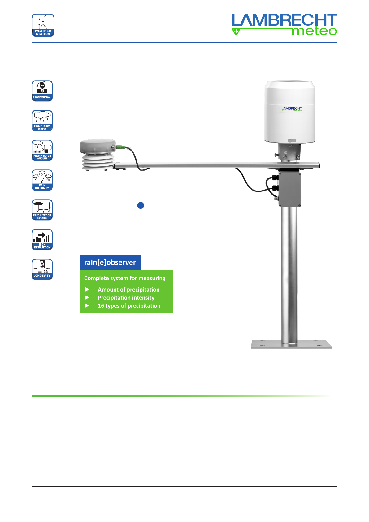
rain[e]observer Precipitation Measuring System
4 Introduction
Withtheextensionsetdescribedhereandtheelectricmodule,inadditiontotheamountandintensityofprecipita-
tion,therain[e]canuseradarmeasurementstodierentiatebetween16typesofprecipitationandthusbecomes
a rain[e]observer. These instructions describe the installation and commissioning of the rain[e]observer and the
extension set.
5 Operating principle
Therain[e]observer’sDopplerradarsendselectromagneticwavesinthemWrangeupwardsviaatransmitting
antenna array, i.e. towards the precipitation. The frequency used is internationally approved for measurements of
thiskind.Thereceivingantennaarrayofthesensorreceivesthesignalreectedbythedropletsorparticles,from
whichthedierencefrequencybetweenthetwosignalsisdetermined.
Theexactfallingspeedofthedrops(particles)canbecalculatedfromthedierencefrequency,whichcombined
with the measurements taken for air temperature and humidity allows for 16 types of precipitation to be determined
anddierentiatedapproximately(seechart).
6 Scope of delivery
Scope of delivery for rain[e]observer installation set · ID no. 32.15184.300000
Note: rain[e] precipitation sensor not included (please order separately)
Item number Designation
32.15184.200000 Detectionofprecipitationtype(observermodule)
32.15184.301000 Observer connection box
33.14627.001010 Aluminumprole840x16E0.75m
33.14627.002000 Mast mount
35.09331.540100 Hexagonal screw M8 x 16 DIN 933 A2
35.67981.500841 Serrated lock washer 8.4 DIN 6798 A A2
69.06500.590000 T nut 8 St M8, galvanized
69.61010.210000 Tension band
69.61010.210100 Turnbuckle
7 Choosing the installation site
Tominimizepossiblespraying,itisrecommendedthatyouavoidlocationswithahardoorsurface(suchas
concrete) and to install the precipitation sensor instead on grass or another soft surface. In general, the sensor
should not be placed on roofs or slopes.
InaccordancewithDWDstandards,werecommendinstallingtheprecipitationsensoratadistanceofatleast2m
ortheobstacleheight(abovethesensoredge)tothenextobstacle(suchastreesorwalls),twicetheobstacle
heightinaccordancewithWMOstandardsorideallyfourtimestheobstacleheight.
Overgrowth by plants around the precipitation sensor must be regularly trimmed back to the height of the sensor
inordertopreventtheresultsbeingfalsiedandtoreducetheeectsofwindatthesametime.
Aspecicpointabouttherain[e]observer’sradarmoduleisthatthereshouldbenolargemovingobjectssuchas
treesorcarsdrivingwithinaradiusofupto10metersinthemodule’seldofvision.Thisappliesinparticularto
movingobjectsatsensorheightaswellasgasdisposallamps(e.g.streetlighting).Theradarsignalsreectedfrom
theseobjectscouldproduceDopplerfrequencies,whichcouldbeincorrectlyinterpretedasprecipitationevents.
Youshouldtakeaccountofpowersurgesandlightningprotectionaswellaspossiblyappropriategrounding
measures required on site in accordance with local regulations.
5


![Lambrecht sun[e] 00.16130.501030 User manual](/data/manuals/t9/m/t9m8/sources/lambrecht-sun-e-00-16130-501030-manual.jpg "Lambrecht sun[e] 00.16130.501030 User manual")


