lancer Soochee 1100 User manual

Soochee™
“Lancer” is the registered trademark of Lancer © 2018 by Lancer, all rights reserved.
Lancer Corporation
6655 Lancer Blvd.
San Antonio, Texas 78219
800-729-1500
Tech Support/Warranty: 800-729-1550
email: custser[email protected]
web: lancercorp.com
Lancer PN: 28-3063
Revision: 00-1, October 2019
Operation Manual
Model 1100
Refrigerated Beverage Dispenser (RBD)

2
TABLE OF CONTENTS
BEFORE GETTING STARTED
Each unit is tested under operating conditions and is thoroughly
inspected before shipment. At the time of shipment, the carrier
accepts responsibility for the unit. Upon receiving the unit, care-
fully inspect the carton for visible damage. If damage exists, have
the carrier note the damage on the freight bill and le a claim with
carrier. Responsibility for damage to the dispenser lies with the
carrier.
The installation and relocation, if necessary, of this product must be carried out by qualied personnel with
up-to-date safety and hygiene knowledge and practical experience, in accordance with current regulations.
Warning........................................................................................2
Basic Safety Rules.................................................................2
Installation.................................................................................4-5
Transport Instructions............................................................4
Unpacking..............................................................................4
Positioning..............................................................................5
ElectricalConnection..............................................................5
Use............................................................................................6-7
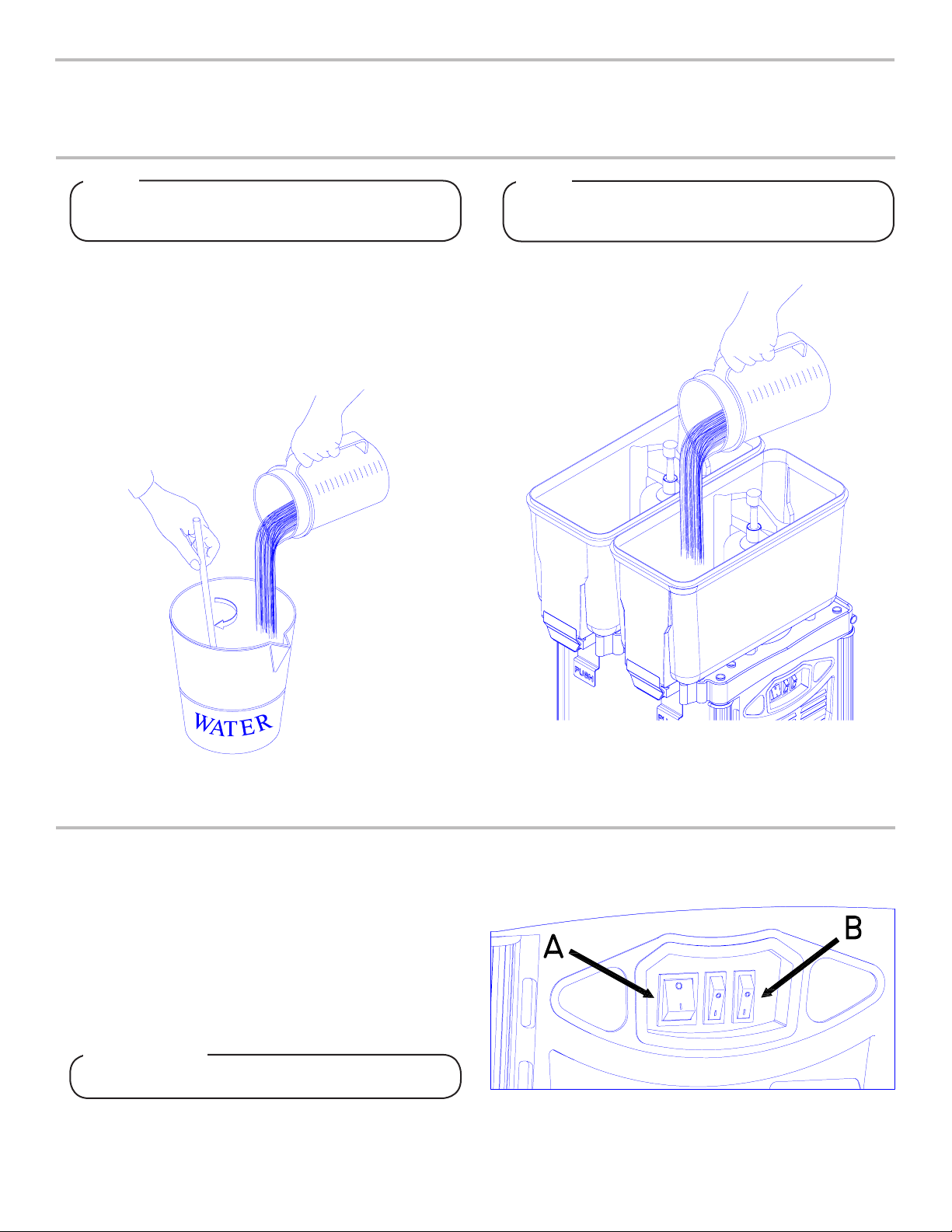
Dispenser Setup....................................................................6
Dispenser Function................................................................6
Beverage Temperature Regulator..........................................7
Cleaning and Sanitizing..........................................................7-8
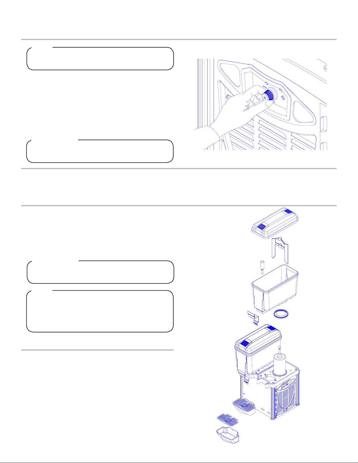
Disassembling and Assembling.............................................7
Cleaning.................................................................................8
Servicing................................................................................8
Troubleshooting..........................................................................9
Illustrations and Part Listing...............................................10-12
Main Unit Assembly..............................................................10
Unit Specications................................................................11
WiringDiagram.....................................................................12
READ ALL SAFETY INSTRUCTIONS BEFORE USING THIS UNIT.
This manual contains important safety information and all applicable safety precautions must be observed. To reduce the
risk of re, electric shock, damage to the equipment or personal injury when using this unit all instuctions/warnings on the
product being used must be followed:
ABOUT THIS MANUAL
This booklet is an integral and essential part of the product.
Please carefully read the guidelines and warnings contained
herein as they are intended to provide the user with essential
information for the continued safe use and maintenance of the
product. In addition, it provides GUIDANCE ONLY to the user on
the correct services and site location of the unit.
Text following the Warning signal indicates a
hazardous situation, which if not avoided, will result
in death or serious injury. Be sure to read all Warning
statements before proceeding with the installation.
! WARNING
Text following the Caution signal indicates a
hazardous situation, which if not avoided, could result
in death or serious injury. Be sure to read the Caution
statements before proceeding with the installation
! CAUTION
Text following the Attention signal addresses a
situation that if not followed could potentially damage
the equipment. Be sure to read the Attention
statements before proceeding
! ATTENTION
Text following the Note signal provides you with
informationthatmayhelpyoumoreeectivelyperform
the installation procedures within this manual.
Disregarding information will not cause damage or
injury, however it may limit the performance of the
dispenser.
NOTE
WARNING
This instruction manual is an integral part of the machine and must be kept for any further consultation.
This machine is a cold drink dispenser.
This machine should be used only for the purpose for which it was designed. Any other use is inappropriate and therefore
dangerous.
The manufacturer will not be held responsible for any damage caused by improper use.
Before installing and operating on the machine read carefully this instruction manual.
The company reserves the right to modify the construction or appearance without notice.

3
IMPORTANT SAFETY INSTRUCTIONS
• The dispenser is for indoor use only
• This appliance is intended to be used in commercial
applications such as restaurants or similar.
• This appliance should not be used by children or
inrm persons without supervision.
• This appliance is not intended for use by persons
(including children) with reduced physical, sensory or
mental capabilities, or lack of experience and knowl-
edge, unless they have been given supervision or in-
struction concerning use of the appliance by a person
responsible for their safety.
• This appliance can be used by children aged from 8
years and above and persons with reduced physical,
sensory or mental capabilities or lack of experience
and knowledge if they have been given supervision or
instruction concerning use of the appliance in a safe
way and understand the hazards involved.
• Cleaning and user maintenance shall not be per-
formed by children without supervision.
• This unit is not a toy and children should be advised
not to play with the appliance.
• Do not operate unit below minimum ambient operation
conditions.
• Should freezing occur, cease operation of the unit and
contact authorized service technician.
• The maximum tilt for safe operation is 5°.
• This appliance must be installed and serviced by a
professional.
! Intended Use
• Follow all local electrical codes when making
connections.
• DO NOT plug into a wall electrical outlet unless the
current shown on the serial number plate agrees with
local current available.
• Each dispenser must have a separate electrical
circuit.
• DO NOT use extension cords with this unit.
• DO NOT ‘gang’ together with other electrical devices
on the same outlet.
• WARNING: Always disconnect electrical power to the
unit to prevent personal injury before attempting any
internal maintenance.
• The resettable breaker switch should not be used as
a substitute for unplugging the dispenser from the
power source to service the unit.
• Only qualied personnel should service internal com-
ponents of electrical control housing.
• WARNING: Make sure that all water lines are tight and
units are dry before making any electrical connections
• If this dispenser is installed in an area that is suscepti-
ble to ±10% variation of the nominal line voltage, con-
sider installing a surge protector or similar protection
device.
F Power
• WARNING: Do not touch the machine when hands or
feet are wet.
• WARNING: Do not use the machine when barefooted.
• WARNING: This appliance can be used by children
aged from 8 years and above and persons with
reduced physical, sensory or mental capabilities or
lack of experience and knowledge if they have been
given supervision or instruction concerning use of the
appliance in a safe way and understand the hazards
involved.
• WARNING: Children shall not play with the appliance.
! Caution
• WARNING: Cleaning and user maintenance shall not be
made by children without supervision.
• WARNING: Do not allow the machine to be used by
children or untrained persons.
• WARNING: Do not leave the machine outside.
• WARNING: Do not pull on the electrical cord when un-
plugging the machine.
! Caution

4
1. Remove cardboard and plastic covering.
2. Make sure that the machine has not been damaged.
3. Remove the plastic lm from all the stainless steel panels.
4. Remove accessory kit and loose parts from dispenser.
5. Before operating remove the green plastic plug from the tap.
DO NOT LAY UNIT ON ITS SIDE OR BACK
! ATTENTION
INSTALLATION
Please read this manual before installation and operation of this dispenser. Please see page 9 for troubleshooting or service assis-
tance. If the service cannot be corrected please call your Service Agent or Lancer Customer Service. Always have your model and
serial number available when you call.
Read This Manual
Unpacking the Dispenser
Inspect unit for concealed damage. If evident, notify
deliveringcarrierandleaclaimagainstthesame.
NOTE
Useful instructions for transport
In order to prevent the oil contained in the air-tight compressor
from owing into the cooling circuit, it is necessary to always
carry, store and handle the machine in a vertical position,
following the instructions found on the packaging.
If the machine was accidentally or purposely placed in
a non-vertical position during transport, before operat-
ing the machine, it should be kept in a straight position
forapproximately30minutes,toallowtheoiltoow
back into the compressor.
! ATTENTION
To assure that beverage service is accessible to all
customers, Lancer recommends that counter height
and equipment selection be planned carefully. The
2010 ADA Standards for Accessible Design states that
themaximumreachheightfromtheoorshouldbeno
more than 48” if touch point is less than 10” from the
front of the counter, or a maximum of 46” if the touch
point is more than 10” and less than 27” from the front
of the counter. For more information about the
customer’s legal requirements for the accessibility of
installed equipment, refer to 2010 ADA Standards for
Accessible Design - http://www.ada.gov.
NOTE
The various packaging should not be left within reach
of children since they are potentially dangerous.
! CAUTION

5
Positioning
In order to facilitate proper dispenser drainage, ensure
that the dispenser is level, front to back and side to
side. Place a level on the top of the rear edge of the
dispenser. The bubble must settle between the level
lines. Repeat this procedure for the remaining three
sides. Level unit if necessary. For optimum perfor-
mance place the unit at a 0° tilt. The maximum tilt is 5°.
Leveling the Dispenser:
1. Place machine on a horizontal and sturdy surface.
2. For an improved ventilation maintain a distance of 15cm (6
inches), between unit and walls or other obstacles.
3. Increase the distance if the obstacles are an heating source.
4. When the dispenser is in place, regulate the legs in order to
keep it level.
Failuretomaintainspeciedclearancewillcausethe
compressor to overheat and will result in compressor
failure
! ATTENTION
The dispenser should only be installed in a location
where it can be overseen by trained personnel
NOTE
Electrical Connection
• Make sure that the machine is properly connected to an
ecient grounding system, in compliance with current
safety standards.
• Make sure that the voltage is in acordance with what
indicated on the “serial number” tag applied on the
chassis.
• Make sure the current available is suecient for the
maximum required by the machine.
• If needed, use only approved multiple outlets, in
compliance with current safty standards.
Before inserting the plug into the eletrical socket, read
the following precautions:
NOTE
The dispenser must be properly electrically grounded
to avoid serious injury or fatal electrical shock. The
power cord has a three-prong grounded plug. If a three-
hole grounded electrical outlet is not available, use an
approved method to ground the unit. Follow all local
electrical codes when making connections. Each dis-
penser must have a separate electrical circuit. Do not
use extension cords. Do not connect multiple electrical
devices on the same outlet.
! WARNING

6
Before use, the dispenser should be cleaned carefully
as it comes into contact with drinks:
NOTE
Dispenser Setup
Relling
1. Before lling up the container make sure to remove the
power plug.
2. Mix product in a separate container.
3. Do not ll the container with hot product.
For a correct usage of the machine ensure that the
liquid level into the bowl does not go below .75 - 1 gal.
NOTE
4. Do not overtake the MAX level line.
Dispenser Function
1. Make sure that the main switch (A) is in the [OFF] position,
plug in the machine.
2. Before starting the machine, ensure that the bowl are
properly closed with their covers.
3. Turn the main switch (A) to [ON] position, the refrigerant
group unit will automatically start.
4. To start the mixing action, turn to [ON] position the mixing
system switch (B). There is a switch for each container.
5. To pour drink out, press lightly the drinking glass against
lever.
DO NOT RUN THE PUMP WITHOUT LIQUID.
! ATTENTION
USE

7
Beverage Temperature Regulator
1. To adjust this temperature, turn the themostat knob clock-
wise to set a lower temperature.
2. If unit has internal themostat, remove left or rear side panel
(machine with 2 compressors).
3. To disassemble the side panels, loosen the screws on the
panels, pushing up then unlatching.
4. To adjust temperature, turn thermostat handle clockwise to
set a lower temperature.
Every dispenser has been tested with the thermostat
set at c.a. +41°F.
NOTE
Before adjusting temperature, always remove the power
plug.
! ATTENTION
CLEANING AND SANITIZING
General Information
• For health standards and quality beverages, clean as often
as possible.
• Cleaning should be accomplished only by trained personnel.
Sanitary gloves are to be used during cleaning operations.
• Applicable safety precautions must be observed. Instruction
warnings on the product being used must be followed.
The cleaning procedures provided herein pertain
totheLancerequipmentidentiedbythismanual.
If other equipment is being cleaned, follow the
guidelines established by the manufacturer for that
equipment.
NOTE
Beforecarryingoutcleaningsandrells,removethe
power plug.
! ATTENTION
Disassembling and Assembling
1. Disconnect the unit by removing the plug.
2. Lift lid o.
3. Pull mixer o.
4. Lift container with both hands by a light, swinging motion
(Should you have diculty it is necessary to dampen steel
refrigerator and gasket, then repeat the operation).
5. To remove container’s gasket, lift it from its setting.
6. To disassemble panels unscrew the nuts on the panels,
pushing up then unlatch.
7. To reassemble the unit, repeat the above operations in
reverse.

8
Cleaning
Do not use abrasive powders which might impair
container and lid’s shine.
! ATTENTION
1. Use neutral soap and lukewarm water to wash container, lid,
mixer, refrigerator and tap.
2. Rinse carefully with water in order to remove any residual of
soap.
3. For sanitation purposes, wash the parts with a solution of
cold water and sodium hypochlorite (bleach) with a 10 gram
(1/2 spoon) per .26 gallon of water ratio.
4. Rinse with lukewarm water. For a better cleaning and sanita-
tion use a soft brush.
5. If the dispenser is out of use for a long period, remove the
power plug and clean carefully all parts; keep the dispenser
away from dust and cover it with a plastic sheet.
Servicing
1. Dispenser servicing is simple.
2. After disconnecting the dispenser, remove panels and clean
inside parts, especially condenser ns, with a brush.
Dust reduces the performance of the machine; so clean
at least once a month.
! ATTENTION
The dispenser does not require oiling.
NOTE
Any necessary repairs on the machine should be
performed exclusively by an authorized repair center,
using original replacement parts. The electrical cord
should not be replaced by the user.
NOTE
To prevent possible harm to the environment from improper disposal, recycle the unit
by locating an authorized recycler or contact the retailer where the product was
purchased. Comply with local regulations regarding disposal of the refrigerant and
insulation.
Dispenser Disposal
A
B
C
A. Bucket
B. Distilled Water
(approx. .26 gallon)
C. Bleach
(approx. 10 grams)

9
TROUBLESHOOTING
TROUBLE CAUSE REMEDY
No power to machine. 1. Plug is not in.
2. Main switch is not to [ON] position.
3. Feeder cable is broken.
4. Main Switch is broken.
1. Insert plug.
2. Switch main switch to [ON].
3. Replace feeder cable.
4. Replace main switch.
Machine is not cooling. 1. Gas leak into the cooling circuit.
2. Condenser is clogged.
3. Fan motor is burnt.
4. Lack of air ow.
1. Find leak, lter it out and re-charge the cooling
circuit.
2. Clean the condenser.
3. Replace fan motor.
4. Increase distance between the machine and
other obstacles/heating sources.
Compressor doesn’t
start.
1. Main switch is broken.
2. Compressor protector is broken.
3. Compressor relay is broken.
4. Compressor motor is broken.
1. Replace main switch.
2. Replace compressor protector.
3. Replace compressor relay.
4. Replace motor.
One bowl is not cooling. 1. Gas leak into the cooling circuit.
2. Condenser is clogged
3. Lack of air ow
4. Tube of the cooling circuit is clogged.
5. Filter is clogged.
1. Find leak, lter it out and re-charge the cooling
circuit.
2. Clean the condenser.
3. Increase distance between the machine and
other obstacles/heating sources.
4. Cut the tube, eliminate clog, re-charge the
cooling circuit.
5. Replace the lter.
The stirring paddles are
not working.
1. The gearbox is broken.
2. The gearbox switch is broken.
1. Replace the gearbox, taking care to assemble
it in the correct position.
2. Replace the gearbox switch.
The pump is not
working.
1. The pump motor is broken.
2. The pump switch is broken.
1. Replace the pump motor.
2. Replace the pump switch.

10
ILLUSTRATIONS AND PART LISTINGS
Main Unit Assembly

11
Position Part Number Description
1
54-1028 LID, BOWL, 3.2 GAL, RBD
2
05-4215 PADDLE, 3.2 GAL, RBD
3
82-6449 PISTON ASSY, RBD
4
82-6444 BOWL ASSY, 3.2 GAL, RBD
5
02-1032 GASKET, BOWL, RBD
6
82-6460 LEVER, PUSH, RBD
6
82-6445 LEVER, PUSH, MEGA, RBD
7
82-6461 VALVE ASSY, RBD
7
82-6447 VALVE ASSY, MEGA, RBD
8
82-6448 SHAFT ASSY, 3.2 GAL, RBD
8
82-6462 SHAFT ASSY, 5.3 GAL, RBD
9
91-4011 MOTOR ASSY, AGITATOR, 3.2 GAL, 120V, RBD
9
91-4012 MOTOR ASSY, AGITATOR, 3.2 GAL, 220V, RBD
9
91-4013 MOTOR ASSY, AGITATOR, DOUBLE BOWL, 220V, RBD
9
91-4020 MOTOR ASSY, AGITATOR, 5.3 GAL, 120V, RBD
9
91-4021 MOTOR ASSY, AGITATOR, 5.3 GAL, 220V, RBD
10
82-6452 PANEL ASSY, SIDE, GRY, RBD
11
26-3005 THERMOSTAT, RBD
12
12-1033 SWITCH, BLACK, RBD
13
12-1032 SWITCH, RED, RBD
14
30-16572 PANEL, FRONT, SINGLE, RBD
14
30-16573 PANEL, FRONT, DOUBLE, RBD
14
30-16574 PANEL, FRONT, TRIPLE, RBD
14
30-16575 PANEL, FRONT, QUAD, RBD
14
30-16568 PANEL, FRONT, QUAD BOWL MEGA, RBD
15
91-4014 MOTOR, FAN, SINGLE BOWL, 220 V, RBD
15
91-4015 MOTOR, FAN, SINGLE BOWL, 120 V, RBD
15
91-4016 MOTOR,FAN,DBL/TRPL BWL 3.2 GAL,DBL/QD BWL 5.3 GAL,120V, RBD
15
91-4017 MOTOR,FAN,DBL/TRPL BWL 3.2 GAL,DBL/QD BWL 5.3 GAL,220V, RBD
15
91-4018 MOTOR, FAN, QUAD BOWL 3.2 GAL, TRIPLE BOWL 5.3 GAL, 120 V, RBD
15
91-4019 MOTOR, FAN, QUAD BOWL 3.2 GAL, TRIPLE BOWL 5.3 GAL, 220 V, RBD
16
54-1029 DRIP TRAY ASSY, SINGLE BOWL, RBD
17
82-6453 LEG ASSY, UL, RBD
18
02-1031 O-RING, PISTON, RBD
19
05-4219 LID, BOWL, 5.3 GAL, RBD
20
05-4220 PADDLE, 5.3 GAL, RBD
21
82-6459 BOWL ASSY, 5.3 GAL, RBD
22
30-16566 PANEL, FRONT, MEGA, RBD
22
30-16567 PANEL, FRONT, TRIPLE BOWL MEGA, RBD
22
30-16569 PANEL, FRONT, DOUBLE MEGA, RBD
23
54-1030 DRIP TRAY ASSY, MEGA BOWL, RBD
24
05-4216 LID, MEGA BOWL, RBD
25
82-6450 BOWL ASSY, 3.2 GAL, MEGA BOWL, RBD
26
82-6451 BOWL ASSY, 5.3 GAL, MEGA BOWL, RBD
27
04-2115 CAP,SCREW HOLE,DRIP PAN,RBD
-
04-2111 SCREW,DRIP PAN,RBD
-
04-2112 SCREW,SIDE PANEL,RBD
-
04-2113 SCREW,FRONT PANEL,RBD
Spare Parts

12
Unit Specications
Lancer Model Lancer PN Descriptions Freq Current Draw Power Compressor Refrigerant Charge Pressure Bowls Capacity Dimensions (WxDxH) Weight
85-11111A-GRY RBD,1100,115V,3.2GAL,SINGLE,GRAY 50 Hz 2.2 A 260 W 1/6 HP Low 104 psig
85-11211A-GRY RBD,1100,230V,3.2GAL,SINGLE,GRAY 50/60 Hz 1.1 A 270 W 1/6 HP High 250 psig
85-11112A-GRY RBD,1100,115V,3.2GAL,DOUBLE,GRAY 50 Hz 2.8 A 400 W 1/6 HP Low 104 psig
85-11212A-GRY RBD,1100,230V,3.2GAL,DOUBLE,GRAY 50/60 Hz 1.3 A 290 W 1/6 HP High 250 psig
85-11113A-GRY RBD,1100,115V,3.2GAL,MEGA,GRAY 50 Hz 2.8 A 400 W 1/6 HP Low 104 psig
85-11213A-GRY RBD,1100,230V,3.2GAL,MEGA,GRAY 50/60 Hz 1.3 A 290 W 1/6 HP High 250 psig
85-11114A-GRY RBD,1100,115V,3.2GAL,TRIPLE,GRAY 50 Hz 4.0 A 550 W 1/3 HP Low 104 psig
85-11214A-GRY RBD,1100,230V,3.2GAL,TRIPLE,GRAY 50/60 Hz 2.0 A 460 W 1/3 HP High 250 psig
85-11115A-GRY RBD,1100,115V,3.2GAL,MEGA+1,GRAY 50 Hz 4.0 A 550 W 1/3 HP Low 104 psig
85-11215A-GRY RBD,1100,230V,3.2GAL,MEGA+1,GRAY 50/60 Hz 2.0 A 460 W 1/3 HP High 250 psig
85-11116A-GRY RBD,1100,115V,3.2GAL,QUAD,GRAY 50 Hz 6.0 A 710 W 1/3+ HP Low 104 psig
85-11216A-GRY RBD,1100,230V,3.2GAL,QUAD,GRAY 50/60 Hz 2.6 A 620 W 1/3+ HP High 250 psig
85-11117A-GRY RBD,1100,115V,3.2GAL,MEGA+2,GRAY 50 Hz 6.0 A 710 W 1/3+ HP Low 104 psig
85-11217A-GRY RBD,1100,230V,3.2GAL,MEGA+2,GRAY 50/60 Hz 2.6 A 620 W 1/3+ HP High 250 psig
85-11118A-GRY RBD,1100,115V,3.2GAL,DOUBLE MEGA,GRAY 50 Hz 6.0 A 710 W 1/3+ HP Low 104 psig
85-11218A-GRY RBD,1100,230V,3.2GAL,DOUBLE MEGA,GRAY 50/60 Hz 2.6 A 620 W 1/3+ HP High 250 psig
85-11121A-GRY RBD,1100,115V,5.3GAL,SINGLE,GRAY 50 Hz 2.2 A 260 W 1/6 HP Low 104 psig
85-11221A-GRY RBD,1100,230V,5.3GAL,SINGLE,GRAY 50/60 Hz 1.2 A 270 W 1/6 HP High 250 psig
85-11122A-GRY RBD,1100,115V,5.3GAL,DOUBLE,GRAY 50 Hz 3.4 A 550 W 1/3 HP Low 104 psig
85-11222A-GRY RBD,1100,230V,5.3GAL,DOUBLE,GRAY 50/60 Hz 2.0 A 340 W 1/3 HP High 250 psig
85-11123A-GRY RBD,1100,115V,5.3GAL,MEGA,GRAY 50 Hz 3.4 A 550 W 1/3 HP Low 104 psig
85-11223A-GRY RBD,1100,230V,5.3GAL,MEGA,GRAY 50/60 Hz 2.0 A 340 W 1/3 HP High 250 psig
85-11124A-GRY RBD,1100,115V,5.3GAL,TRIPLE,GRAY 50 Hz 7.0 A 730 W 1/3+ HP Low 104 psig
85-11224A-GRY RBD,1100,230V,5.3GAL,TRIPLE,GRAY 50/60 Hz 2.6 A 630 W 1/3+ HP High 250 psig
85-11125A-GRY RBD,1100,115V,5.3GAL,MEGA+1,GRAY 50 Hz 7.0 A 730 W 1/3+ HP Low 104 psig
85-11225A-GRY RBD,1100,230V,5.3GAL,MEGA+1,GRAY 50/60 Hz 2.6 A 630 W 1/3+ HP High 250 psig
85-11126A-GRY RBD,1100,115V,5.3GAL,QUAD,GRAY 50 Hz 7.0 A
1100 W
2 (1/3 HP) Low 104 psig
85-11226A-GRY RBD,1100,230V,5.3GAL,QUAD,GRAY 50/60 Hz 4.0 A 680 W 2 (1/3 HP) High 250 psig
85-11127A-GRY RBD,1100,115V,5.3GAL,MEGA+2,GRAY 50 Hz 7.0 A
1100 W
2 (1/3 HP) Low 104 psig
85-11227A-GRY RBD,1100,230V,5.3GAL,MEGA+2,GRAY 50/60 Hz 4.0 A 680 W 2 (1/3 HP) High 250 psig
85-11128A-GRY RBD,1100,115V,5.3GAL,DOUBLE MEGA,GRAY 50 Hz 7.0 A
1100 W
2 (1/3 HP) Low 104 psig
85-11228A-GRY RBD,1100,230V,5.3GAL,DOUBLE MEGA,GRAY 50/60 Hz 4.0 A 680 W 2 (1/3 HP) High 250 psig
44.1 lb
20 kg
Soochee 3.2 R134a 4.9 oz 22 x 3.2 Gal 16.3 x 16.9 x 27.7 inches 63.9 lb
29 kg
Soochee 3.1 R134a 2.5 oz 11 x 3.2 Gal 8.2 x 16.9 x 27.7 inches
61.7 lb
28 kg
Soochee 3.3 R134a 8.8 oz 33 x 3.2 Gal 24.2 x 16.9 x 27.7 inches 90.4 lb
41 kg
Soochee 6.1 R134a 4.9 oz 11 x 6.6 Gal 16.3 x 16.9 x 26 inches
88.2 lb
40 kg
Soochee 3.4 R134a 10.5 oz 44 x 3.2 Gal 32 x 16.9 x 27.7 inches 116.8 lb
53 kg
Soochee 3.2C R134a 8.8 oz 2
1 x 6.6 Gal
+
1 x 3.2 Gal
24.2 x 16.9 x 27.7 inches
114.6 lb
52 kg
Soochee 6.2 R134a 10.5 oz 22 x 6.6 Gal 32 x 16.9 x 26 inches 114.6 lb
52 kg
Soochee 3.3C R134a 10.5 oz 3
1 x 6.6 Gal
+
2 x 3.2 Gal
32 x 16.9 x 27.7 inches
46.3 lb
21 kg
Soochee 5.2 R134a 7.4 oz 22 x 5.3 Gal 16.3 x 16.9 x 27.7 inches 72.8 lb
33 kg
Soochee 5.1 R134a 3.2 oz 11 x 5.3 Gal 8.2 x 16.9 x 27.7 inches
70.5 lb
32 kg
Soochee 5.3 R134a 11.5 oz 33 x 5.3 Gal 24.2 x 16.9 x 27.7 inches 97 lb
44 kg
Soochee X.1 R134a 7.4 oz 11 x 10.6 Gal 16.3 x 16.9 x 28.9 inches
94.8 lb
43 kg
Soochee 5.4 R134a 2 (7.4 oz) 44 x 5.3 Gal 32 x 16.9 x 27.7 inches 141.1 lb
64 kg
Soochee 5.2C R134a 11.5 oz 2
1 x 10.6 Gal
+
1 x 5.3 Gal
24.2 x 16.9 x 28.9 inches
138.9 lb
63 kg
Soochee X.2 R134a 2 (7.4 oz) 22 x 10.6 Gal 32 x 16.9 x 28.9 inches 134.5 lb
61 kg
Soochee 5.3C R134a 2 (7.4 oz) 3
1 x 10.6 Gal
+
2 x 5.3 Gal
32 x 16.9 x 28.9 inches

13
Wiring Diagram
c = Compressor
S = Exchanger
F = Filter
Bc = Boiler-collector
E1 = Evaporator
E2 = Evaporator
E3 = Evaporator
D = Distributor
Ca = Capillary
1 = Unloading line
2 = Liquid Line
3 = Suction Line
T = Thermostat
Soochee 6.1-6.2, X.1
Soochee 5.1-5.2-5.3
Soochee 3.1-3.2, 3.3, 3.4
Soochee X.2
Soochee 5.4
Soochee 3.2, 5.2, 6.1, X.1
Soochee 3.3, 5.3
Soochee 3.4, 5.4, 6.2, X.2
Table of contents
Other lancer Beverage Dispenser manuals

lancer
lancer Bevariety ACIB Series User manual

lancer
lancer 85-3151R-VV User manual

lancer
lancer Sensation 30 User manual

lancer
lancer Sensation User manual

lancer
lancer 14400 SERIES Manual

lancer
lancer 14800 Series Manual

lancer
lancer BEVARIETY MCY-22 Manual

lancer
lancer Blue Star IBD CB Series 22 User manual

lancer
lancer FLAVOR SELECT 22 Manual

lancer
lancer 28-0586/07 User manual
Popular Beverage Dispenser manuals by other brands

Concordia
Concordia XPRESS Technician manual

SaniServ
SaniServ A7081HEP Operation manual

Grindmaster
Grindmaster G-Cool Mini-Quattro C-4D Specifications

Cornelius
Cornelius IDC PRO 255 installation instructions

Avanti
Avanti BUILT-IN BEVERAGE CENTER BCA5102SS instruction manual

Klarstein
Klarstein KonfiStar 40 Digital manual