LANCIER Monitoring RTS 1000 User manual

BA 074890.020/11.14
Original operating instructions
RTS 1000
Pressurisation System
with addressable compressor
monitoring unit ACS

Page 2
Contents
Ordering data . . . . . . . . . . . . . . . . . . . . . . . . . . . . . . . . . . . . . . . . . . . . . . . . . . . . . . . . . . . . . . . . . . . . . . . . . . . . . . . . . . . .4
Technical specifications . . . . . . . . . . . . . . . . . . . . . . . . . . . . . . . . . . . . . . . . . . . . . . . . . . . . . . . . . . . . . . . . . . . . . . . . . . .4
Scope of supply . . . . . . . . . . . . . . . . . . . . . . . . . . . . . . . . . . . . . . . . . . . . . . . . . . . . . . . . . . . . . . . . . . . . . . . . . . . . . . . . . .5
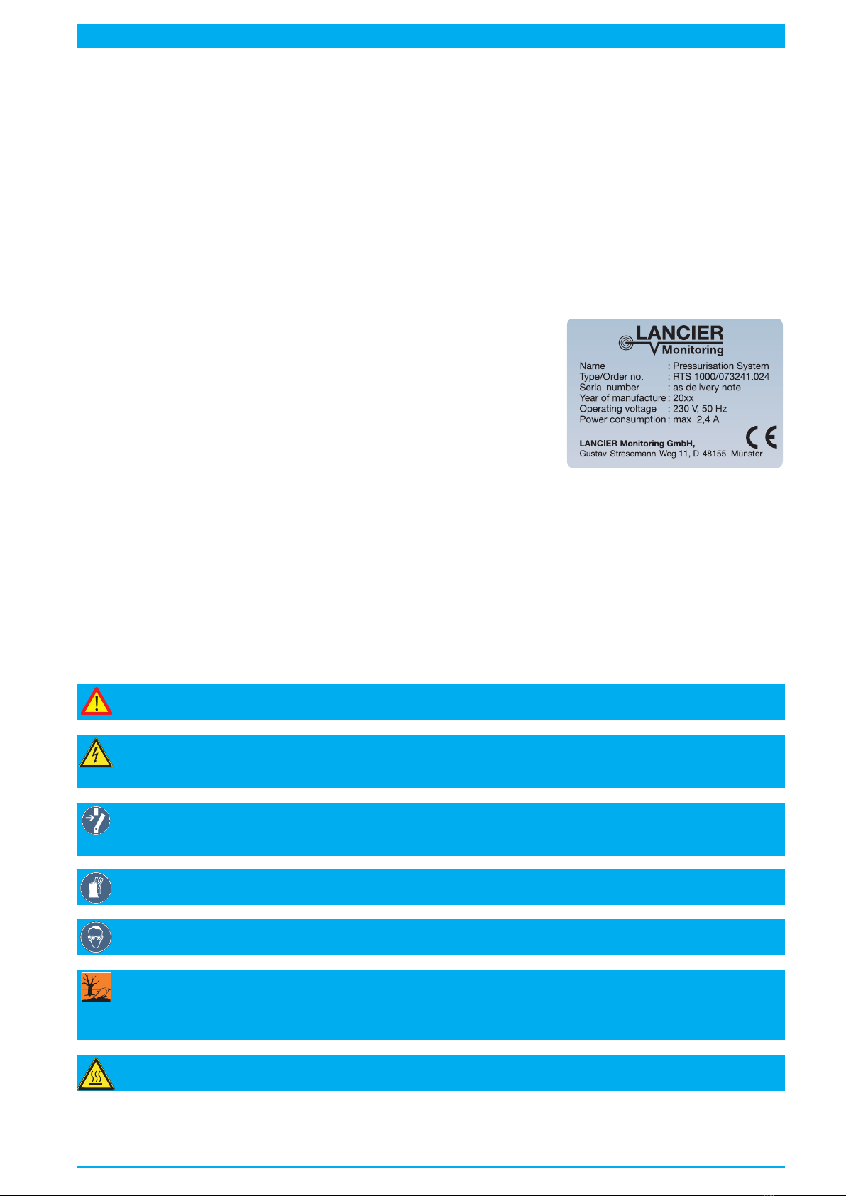
Marking . . . . . . . . . . . . . . . . . . . . . . . . . . . . . . . . . . . . . . . . . . . . . . . . . . . . . . . . . . . . . . . . . . . . . . . . . . . . . . . . . . . . . . . .5
Symbols used . . . . . . . . . . . . . . . . . . . . . . . . . . . . . . . . . . . . . . . . . . . . . . . . . . . . . . . . . . . . . . . . . . . . . . . . . . . . . . . . . . .5
Legal provisions . . . . . . . . . . . . . . . . . . . . . . . . . . . . . . . . . . . . . . . . . . . . . . . . . . . . . . . . . . . . . . . . . . . . . . . . . . . . . . . . .6
Liability . . . . . . . . . . . . . . . . . . . . . . . . . . . . . . . . . . . . . . . . . . . . . . . . . . . . . . . . . . . . . . . . . . . . . . . . . . . . . . . . . . . . .6
Warranty . . . . . . . . . . . . . . . . . . . . . . . . . . . . . . . . . . . . . . . . . . . . . . . . . . . . . . . . . . . . . . . . . . . . . . . . . . . . . . . . . . . . .6
General . . . . . . . . . . . . . . . . . . . . . . . . . . . . . . . . . . . . . . . . . . . . . . . . . . . . . . . . . . . . . . . . . . . . . . . . . . . . . . . . . . . . . . . . .6
Conventional use . . . . . . . . . . . . . . . . . . . . . . . . . . . . . . . . . . . . . . . . . . . . . . . . . . . . . . . . . . . . . . . . . . . . . . . . . . . . . . . . .7
Safety instructions . . . . . . . . . . . . . . . . . . . . . . . . . . . . . . . . . . . . . . . . . . . . . . . . . . . . . . . . . . . . . . . . . . . . . . . . . . . . . . .7
For the safety of persons in charge . . . . . . . . . . . . . . . . . . . . . . . . . . . . . . . . . . . . . . . . . . . . . . . . . . . . . . . . . . . . . .7
Operator . . . . . . . . . . . . . . . . . . . . . . . . . . . . . . . . . . . . . . . . . . . . . . . . . . . . . . . . . . . . . . . . . . . . . . . . . . . . . . . . . . .7
Qualified employees . . . . . . . . . . . . . . . . . . . . . . . . . . . . . . . . . . . . . . . . . . . . . . . . . . . . . . . . . . . . . . . . . . . . . . . . .7
Staff qualification . . . . . . . . . . . . . . . . . . . . . . . . . . . . . . . . . . . . . . . . . . . . . . . . . . . . . . . . . . . . . . . . . . . . . . . . . . . .7
General safety instructions . . . . . . . . . . . . . . . . . . . . . . . . . . . . . . . . . . . . . . . . . . . . . . . . . . . . . . . . . . . . . . . . . . . . .8
Safety instructions for electrical works . . . . . . . . . . . . . . . . . . . . . . . . . . . . . . . . . . . . . . . . . . . . . . . . . . . . . . . . . . .9
Safety instructions for works on compressed air lines and pressure tanks . . . . . . . . . . . . . . . . . . . . . . . . . . . . .9
Safety instructions for working with drying agents . . . . . . . . . . . . . . . . . . . . . . . . . . . . . . . . . . . . . . . . . . . . . . . . . .9
Safety devices . . . . . . . . . . . . . . . . . . . . . . . . . . . . . . . . . . . . . . . . . . . . . . . . . . . . . . . . . . . . . . . . . . . . . . . . . . . . . . .10
Remaining dangers . . . . . . . . . . . . . . . . . . . . . . . . . . . . . . . . . . . . . . . . . . . . . . . . . . . . . . . . . . . . . . . . . . . . . . . . . . .10
Service conditions . . . . . . . . . . . . . . . . . . . . . . . . . . . . . . . . . . . . . . . . . . . . . . . . . . . . . . . . . . . . . . . . . . . . . . . . . . . . . . .10
Temperatures . . . . . . . . . . . . . . . . . . . . . . . . . . . . . . . . . . . . . . . . . . . . . . . . . . . . . . . . . . . . . . . . . . . . . . . . . . . . . . . .10
Ambient conditions . . . . . . . . . . . . . . . . . . . . . . . . . . . . . . . . . . . . . . . . . . . . . . . . . . . . . . . . . . . . . . . . . . . . . . . . . . .10
Installation conditions . . . . . . . . . . . . . . . . . . . . . . . . . . . . . . . . . . . . . . . . . . . . . . . . . . . . . . . . . . . . . . . . . . . . . . . . .10
Transportation . . . . . . . . . . . . . . . . . . . . . . . . . . . . . . . . . . . . . . . . . . . . . . . . . . . . . . . . . . . . . . . . . . . . . . . . . . . . . . . . . .11
Storage . . . . . . . . . . . . . . . . . . . . . . . . . . . . . . . . . . . . . . . . . . . . . . . . . . . . . . . . . . . . . . . . . . . . . . . . . . . . . . . . . . . . . . . .11
General information on storage . . . . . . . . . . . . . . . . . . . . . . . . . . . . . . . . . . . . . . . . . . . . . . . . . . . . . . . . . . . . . . . .11
Functionality of pressurization system RTS 1000 . . . . . . . . . . . . . . . . . . . . . . . . . . . . . . . . . . . . . . . . . . . . . . . . . . . .11
Product description . . . . . . . . . . . . . . . . . . . . . . . . . . . . . . . . . . . . . . . . . . . . . . . . . . . . . . . . . . . . . . . . . . . . . . . . . . . . .12
Product marking, connection and operation . . . . . . . . . . . . . . . . . . . . . . . . . . . . . . . . . . . . . . . . . . . . . . . . . . . . . .12
Instrument panel . . . . . . . . . . . . . . . . . . . . . . . . . . . . . . . . . . . . . . . . . . . . . . . . . . . . . . . . . . . . . . . . . . . . . . . . . . . . .13
Pressurised air supply, storage, drying and monitoring . . . . . . . . . . . . . . . . . . . . . . . . . . . . . . . . . . . . . . . . . . . . .14
Electrics . . . . . . . . . . . . . . . . . . . . . . . . . . . . . . . . . . . . . . . . . . . . . . . . . . . . . . . . . . . . . . . . . . . . . . . . . . . . . . . . . . . .16
Multifunctional Relay MFR . . . . . . . . . . . . . . . . . . . . . . . . . . . . . . . . . . . . . . . . . . . . . . . . . . . . . . . . . . . . . . . . . . . . .17
Mounting . . . . . . . . . . . . . . . . . . . . . . . . . . . . . . . . . . . . . . . . . . . . . . . . . . . . . . . . . . . . . . . . . . . . . . . . . . . . . . . . . . . . . .18
Connect the diffusor condensate discharge hose (10) . . . . . . . . . . . . . . . . . . . . . . . . . . . . . . . . . . . . . . . . . . . . .18
Electrical connection . . . . . . . . . . . . . . . . . . . . . . . . . . . . . . . . . . . . . . . . . . . . . . . . . . . . . . . . . . . . . . . . . . . . . . . . . . . .18
Operating voltage 230 V AC . . . . . . . . . . . . . . . . . . . . . . . . . . . . . . . . . . . . . . . . . . . . . . . . . . . . . . . . . . . . . . . . . .18
Compressor maintenance . . . . . . . . . . . . . . . . . . . . . . . . . . . . . . . . . . . . . . . . . . . . . . . . . . . . . . . . . . . . . . . . . . . . .19
Compressor spare parts . . . . . . . . . . . . . . . . . . . . . . . . . . . . . . . . . . . . . . . . . . . . . . . . . . . . . . . . . . . . . . . . . . . . . . .19
Fault remedy . . . . . . . . . . . . . . . . . . . . . . . . . . . . . . . . . . . . . . . . . . . . . . . . . . . . . . . . . . . . . . . . . . . . . . . . . . . . . . . .19
Operation of the Compressor Monitoring Unit ACS . . . . . . . . . . . . . . . . . . . . . . . . . . . . . . . . . . . . . . . . . . . . . . . . . . .20
Start the ACS . . . . . . . . . . . . . . . . . . . . . . . . . . . . . . . . . . . . . . . . . . . . . . . . . . . . . . . . . . . . . . . . . . . . . . . . . . . . . .20
Operating the ACS . . . . . . . . . . . . . . . . . . . . . . . . . . . . . . . . . . . . . . . . . . . . . . . . . . . . . . . . . . . . . . . . . . . . . . . . .20
Read ACS values . . . . . . . . . . . . . . . . . . . . . . . . . . . . . . . . . . . . . . . . . . . . . . . . . . . . . . . . . . . . . . . . . . . . . . . . . . .20
Read MFR values . . . . . . . . . . . . . . . . . . . . . . . . . . . . . . . . . . . . . . . . . . . . . . . . . . . . . . . . . . . . . . . . . . . . . . . . . .22
Reset maintenance counter . . . . . . . . . . . . . . . . . . . . . . . . . . . . . . . . . . . . . . . . . . . . . . . . . . . . . . . . . . . . . . . . . . .22
Poll MFR alarm conditions . . . . . . . . . . . . . . . . . . . . . . . . . . . . . . . . . . . . . . . . . . . . . . . . . . . . . . . . . . . . . . . . . . .22
Test of MFR alarmdisplay . . . . . . . . . . . . . . . . . . . . . . . . . . . . . . . . . . . . . . . . . . . . . . . . . . . . . . . . . . . . . . . . . . . .22
Deactivating humidity monitoring of the MFR . . . . . . . . . . . . . . . . . . . . . . . . . . . . . . . . . . . . . . . . . . . . . . . . . . . . .22
Read MFR settings . . . . . . . . . . . . . . . . . . . . . . . . . . . . . . . . . . . . . . . . . . . . . . . . . . . . . . . . . . . . . . . . . . . . . . . . .23
Read MFR info . . . . . . . . . . . . . . . . . . . . . . . . . . . . . . . . . . . . . . . . . . . . . . . . . . . . . . . . . . . . . . . . . . . . . . . . . . . .23
Read display info . . . . . . . . . . . . . . . . . . . . . . . . . . . . . . . . . . . . . . . . . . . . . . . . . . . . . . . . . . . . . . . . . . . . . . . . . .23
Service mode . . . . . . . . . . . . . . . . . . . . . . . . . . . . . . . . . . . . . . . . . . . . . . . . . . . . . . . . . . . . . . . . . . . . . . . . . . . . . . . .24
ACS settings . . . . . . . . . . . . . . . . . . . . . . . . . . . . . . . . . . . . . . . . . . . . . . . . . . . . . . . . . . . . . . . . . . . . . . . . . . . . . .24
MFR settings . . . . . . . . . . . . . . . . . . . . . . . . . . . . . . . . . . . . . . . . . . . . . . . . . . . . . . . . . . . . . . . . . . . . . . . . . . . . .24
ACS set „top value” . . . . . . . . . . . . . . . . . . . . . . . . . . . . . . . . . . . . . . . . . . . . . . . . . . . . . . . . . . . . . . . . . . . . . . . . .25
Set up Air Flow Value . . . . . . . . . . . . . . . . . . . . . . . . . . . . . . . . . . . . . . . . . . . . . . . . . . . . . . . . . . . . . . . . . . . . . . .25

Page 3
Important!
It is imperative to read and observe the safety instructions prior to start up!
Operation of multifunctional relay MFR . . . . . . . . . . . . . . . . . . . . . . . . . . . . . . . . . . . . . . . . . . . . . . . . . . . . . . . . . . . . .26
Meaning of the LEDs . . . . . . . . . . . . . . . . . . . . . . . . . . . . . . . . . . . . . . . . . . . . . . . . . . . . . . . . . . . . . . . . . . . . . . . . . .26
Normal operation . . . . . . . . . . . . . . . . . . . . . . . . . . . . . . . . . . . . . . . . . . . . . . . . . . . . . . . . . . . . . . . . . . . . . . . . . . .26
Alarms . . . . . . . . . . . . . . . . . . . . . . . . . . . . . . . . . . . . . . . . . . . . . . . . . . . . . . . . . . . . . . . . . . . . . . . . . . . . . . . . . . .26
Buttons . . . . . . . . . . . . . . . . . . . . . . . . . . . . . . . . . . . . . . . . . . . . . . . . . . . . . . . . . . . . . . . . . . . . . . . . . . . . . . . . . .27
Fuses . . . . . . . . . . . . . . . . . . . . . . . . . . . . . . . . . . . . . . . . . . . . . . . . . . . . . . . . . . . . . . . . . . . . . . . . . . . . . . . . . . . .27
Start-up . . . . . . . . . . . . . . . . . . . . . . . . . . . . . . . . . . . . . . . . . . . . . . . . . . . . . . . . . . . . . . . . . . . . . . . . . . . . . . . . . . . . . . .28
Before start-up . . . . . . . . . . . . . . . . . . . . . . . . . . . . . . . . . . . . . . . . . . . . . . . . . . . . . . . . . . . . . . . . . . . . . . . . . . . . . .28
Set the equipment into operation / charge equipment . . . . . . . . . . . . . . . . . . . . . . . . . . . . . . . . . . . . . . . . . . . . . .28
Function testing / setting of components . . . . . . . . . . . . . . . . . . . . . . . . . . . . . . . . . . . . . . . . . . . . . . . . . . . . . . . . . . .30
Check and set reference value motor protective switch back-up fuse . . . . . . . . . . . . . . . . . . . . . . . . . . . . . . . .30
Check and set cable pressure (pressure reducer) . . . . . . . . . . . . . . . . . . . . . . . . . . . . . . . . . . . . . . . . . . . . . . . . . .30
Check clock pulse air dryer change-over . . . . . . . . . . . . . . . . . . . . . . . . . . . . . . . . . . . . . . . . . . . . . . . . . . . . . . . . .31
Compressor runtime surveillance . . . . . . . . . . . . . . . . . . . . . . . . . . . . . . . . . . . . . . . . . . . . . . . . . . . . . . . . . . . . . .31
Check and set pressure monitor . . . . . . . . . . . . . . . . . . . . . . . . . . . . . . . . . . . . . . . . . . . . . . . . . . . . . . . . . . . . . . . .32
Check and set pressure limiting valve . . . . . . . . . . . . . . . . . . . . . . . . . . . . . . . . . . . . . . . . . . . . . . . . . . . . . . . . . . .33
Check humidity monitoring . . . . . . . . . . . . . . . . . . . . . . . . . . . . . . . . . . . . . . . . . . . . . . . . . . . . . . . . . . . . . . . . . . . .34
Operation On - Off . . . . . . . . . . . . . . . . . . . . . . . . . . . . . . . . . . . . . . . . . . . . . . . . . . . . . . . . . . . . . . . . . . . . . . . . . . . . . .36
Connection equipment pneumatics . . . . . . . . . . . . . . . . . . . . . . . . . . . . . . . . . . . . . . . . . . . . . . . . . . . . . . . . . . . . .36
Normal mode . . . . . . . . . . . . . . . . . . . . . . . . . . . . . . . . . . . . . . . . . . . . . . . . . . . . . . . . . . . . . . . . . . . . . . . . . . . . . . . .36
Shut down operation . . . . . . . . . . . . . . . . . . . . . . . . . . . . . . . . . . . . . . . . . . . . . . . . . . . . . . . . . . . . . . . . . . . . . . . . . .36
Emergency mode . . . . . . . . . . . . . . . . . . . . . . . . . . . . . . . . . . . . . . . . . . . . . . . . . . . . . . . . . . . . . . . . . . . . . . . . . . . .37
Shut down operation . . . . . . . . . . . . . . . . . . . . . . . . . . . . . . . . . . . . . . . . . . . . . . . . . . . . . . . . . . . . . . . . . . . . . . . . . .37
General comments . . . . . . . . . . . . . . . . . . . . . . . . . . . . . . . . . . . . . . . . . . . . . . . . . . . . . . . . . . . . . . . . . . . . . . . . . . .38
Maintenance . . . . . . . . . . . . . . . . . . . . . . . . . . . . . . . . . . . . . . . . . . . . . . . . . . . . . . . . . . . . . . . . . . . . . . . . . . . . . . . . . . .38
Cleaning or changing compressor air intake filters . . . . . . . . . . . . . . . . . . . . . . . . . . . . . . . . . . . . . . . . . . . . . . . .38
Change micro filter element of micro filter . . . . . . . . . . . . . . . . . . . . . . . . . . . . . . . . . . . . . . . . . . . . . . . . . . . . . . .39
Maintenance of air dryers . . . . . . . . . . . . . . . . . . . . . . . . . . . . . . . . . . . . . . . . . . . . . . . . . . . . . . . . . . . . . . . . . . . . . .40
Causes and remedy of faults . . . . . . . . . . . . . . . . . . . . . . . . . . . . . . . . . . . . . . . . . . . . . . . . . . . . . . . . . . . . . . . . . . . . . .42
What to do after "humidity fault"? . . . . . . . . . . . . . . . . . . . . . . . . . . . . . . . . . . . . . . . . . . . . . . . . . . . . . . . . . . . . . .43
Disposal . . . . . . . . . . . . . . . . . . . . . . . . . . . . . . . . . . . . . . . . . . . . . . . . . . . . . . . . . . . . . . . . . . . . . . . . . . . . . . . . . . . . . . .45
Contact: . . . . . . . . . . . . . . . . . . . . . . . . . . . . . . . . . . . . . . . . . . . . . . . . . . . . . . . . . . . . . . . . . . . . . . . . . . . . . . . . . .45
Shipping address: . . . . . . . . . . . . . . . . . . . . . . . . . . . . . . . . . . . . . . . . . . . . . . . . . . . . . . . . . . . . . . . . . . . . . . . . . .45
Replacement parts . . . . . . . . . . . . . . . . . . . . . . . . . . . . . . . . . . . . . . . . . . . . . . . . . . . . . . . . . . . . . . . . . . . . . . . . . . . . . .46
Display, operation . . . . . . . . . . . . . . . . . . . . . . . . . . . . . . . . . . . . . . . . . . . . . . . . . . . . . . . . . . . . . . . . . . . . . . . . . .46
Air dryers . . . . . . . . . . . . . . . . . . . . . . . . . . . . . . . . . . . . . . . . . . . . . . . . . . . . . . . . . . . . . . . . . . . . . . . . . . . . . . . . .48
Compressor PK 24/1 . . . . . . . . . . . . . . . . . . . . . . . . . . . . . . . . . . . . . . . . . . . . . . . . . . . . . . . . . . . . . . . . . . . . . . .48
Micro filter . . . . . . . . . . . . . . . . . . . . . . . . . . . . . . . . . . . . . . . . . . . . . . . . . . . . . . . . . . . . . . . . . . . . . . . . . . . . . . . .49
Electric equipment . . . . . . . . . . . . . . . . . . . . . . . . . . . . . . . . . . . . . . . . . . . . . . . . . . . . . . . . . . . . . . . . . . . . . . . . . .49
Plans . . . . . . . . . . . . . . . . . . . . . . . . . . . . . . . . . . . . . . . . . . . . . . . . . . . . . . . . . . . . . . . . . . . . . . . . . . . . . . . . . . . . . . . . . .50
Equipment lists pneumatics . . . . . . . . . . . . . . . . . . . . . . . . . . . . . . . . . . . . . . . . . . . . . . . . . . . . . . . . . . . . . . . . . .50
Pneumatics diagram Nr. 074891.000 . . . . . . . . . . . . . . . . . . . . . . . . . . . . . . . . . . . . . . . . . . . . . . . . . . . . . . . . . . .51
Equipment list electrics . . . . . . . . . . . . . . . . . . . . . . . . . . . . . . . . . . . . . . . . . . . . . . . . . . . . . . . . . . . . . . . . . . . . . .52
Circuit diagram Nr. 074880.000 . . . . . . . . . . . . . . . . . . . . . . . . . . . . . . . . . . . . . . . . . . . . . . . . . . . . . . . . . . . . . . .53
Equipment list electrics . . . . . . . . . . . . . . . . . . . . . . . . . . . . . . . . . . . . . . . . . . . . . . . . . . . . . . . . . . . . . . . . . . . . . .54
Wiring diagram Nr. 074881.000 . . . . . . . . . . . . . . . . . . . . . . . . . . . . . . . . . . . . . . . . . . . . . . . . . . . . . . . . . . . . . . . .55
EC Declaration of Conformity . . . . . . . . . . . . . . . . . . . . . . . . . . . . . . . . . . . . . . . . . . . . . . . . . . . . . . . . . . . . . . . . . . . . .56
© 2014 LANCIER Monitoring GmbH This operating instruction must not be reproduced or made available,
either complete or in extracts, before the specific consent of LANCIER Monitoring GmbH.

Page 4
Technical specifications
Pressurization System Type RTS 1000
Output power 1000 Nl/h, 0 .. -20 %
Number of consumer load connection point 1
Compressor PK 24/1
Number of cylinders 1
Engine RPM 1425 min-1
Operating voltage 230 V, 1 Phase
Frequency 50 Hz
Current consumption of of the system approx. 2,4 A
Working pressure of compressors max. 6,1 bar
Opening pressure safety valve "compressor" 7,0 bar ± 10 %
Working pressure On-Off 3,0 to 5,0 bar
Opening pressure safety valve "high-pressure" 7,0 bar
Output pressure is adjustable (customised) 0,6 - 0,8 bar
Opening pressure safety valve "output pressure" 0,9 bar + 10 %
Relative humidity output air (typical) approx 1,5 %
Regeneration air mass approx. 270-300 l/h ±10 %
Regeneration time drying agent container 60 s
Content - air storage tank 6 l
Ambient temperature limit +1 °C bis +40 °C
Ambient humidity limit 0 .. 90 % rel. humidity, non condensing
Signal LEDs (standard) Operation (DC)
Fault (A)
Signal output (floating) Accumulative Fault (A - humidity, runtime)
Workplace-related emission value 68 dB(A)
Measurement uncertainty dB(A) ± 2,3 dB(A)
Measuring system DIN 45635 section 1
Measuring conditions in the room
Measurements: Width x Depth x Height 600 x 400 x 880 mm
Weight approx. 65 kg
All pressure specifications are seen as gauge pressure specifications.
Ordering data
Pressurisation System RTS 1000
with addressable compressor monitoring unit ACS,230 V, 50 Hz Order no. 073241.024

Page 5
Scope of supply
• Pressurization system RTS 1000D, consisting of
- 1 solid metal cabinet with the following mounting parts:
- 1 compressor
- 1 air storage tank
- 1 air dryer system
- various control, measuring and display elements
• Condensate diffusor with hose
• Operating instructions
• CE Declaration of Conformity
Marking
The pressurisation system is clearly marked by the content of the name
plate including technical specifications and manufacturer's instructions.
The name plate is found inside at the bottom of the cabinet.
The compressor on the mounting console is marked by the content of the
name plate including technical specifications and manufacturer's instruc-
tions. The name plate is found on the compressors housing.
Accompanying Documents
Documents delivered with this operating instructions are intended to assist for safe and secure operation of
the system.
• Certificate for savety valve and air storage tank
• A3 wiring diagram
• A3 circuit diagram
The system should be put into operation only if all documents have been read and understood by the operator.
Symbols used
Attention Danger!
This symbol warns of the health risks up to threatening injuries or death.
Warning Danger of electric voltage!
This symbol warns of the health risks up to threatening injuries or death
caused by electric voltage.
Turn power off!
This symbol indicates that electrical components and systems must be disconnected prior to
maintenance and repair work and also protected against resetting.
Wear protective gloves!
This symbol indicates that protective gloves must be worn during the works described.
Wear safety glasses!
This symbol indicates that safety glasses must be worn during the works described.
Note for disposal!
This symbol indicates that the resulting waste must be disposed ecologically and not become
domestic waste.
Risk of injury!
Take caution with heated components!

Page 6
Legal provisions
Liability
The information, data and references specified in this operating instruction were up-to-date on the day of print.
Claims on systems already supplied can only be asserted conditionally from details, illustrations and descrip-
tions.
LANCIER Monitoring GmbH assume no liability for damages and disruption of operations, which may result
from:
• Non compliant use
• Arbitrary change to the equipment
• Improper work on and with the equipment
• Operating and setting error
• Disregarding existing standards, directives and accident prevention regulations
• Disregarding operating instruction
Warranty
• Warranty takes place according to the general terms and conditions of LANCIER Monitoring GmbH.
• Warranty claims must be asserted to LANCIER Monitoring GmbH immediately upon detecting a fault or fail-
ure.
• The warranty terminates in all cases where also no liability claims can be asserted.
General
This operating instruction is valid for the the pressurization system RTS 1000 and its variants.
It shall help you to get to know the product and contains important information to operate the system safely,
properly and economically, to make use of the range of functions, to lessen repair costs and down times, as
well as to increase the reliability and service life of the equipment.
Furthermore, this manual will enable you to carry out maintenance and repair work on the pressurization sys-
tem yourself for daily use.
It contains safety instructions, which must be observed.
During operation, other instructions must be observed if necessary for components to be installed optionally,
such as flow meter, distribution devices etc.
The operating instruction is supplemented with instructions on the basis of current national regulations on
accident prevention and environmental protection.
The operating instruction must always be on hand at the point where the equipment is used, complete and in
legible condition.
The operating instruction shall be read and applied by anyone assigned to work with/on the
system, e.g. during
• operation, including installation, setting up, fault repair in the production flow, removal of
production waste, care, disposal of materials.
• Maintenance (servicing, inspection, repair)
• Transportation
Besides the instruction manual and the accident prevention regulations applicable in the country and site of
use, the recognised specialised rules for safe and professional work shall also be observed.
This documentation was compiled with the utmost diligence, taking the existing regulations into consideration.
However, variations cannot be excluded. LANCIER Monitoring reserves the right to make technical modifica-
tions to the pressurization system without prior notification and assumes no legal responsibility or liability for
damages, which may arise.
Any necessary changes are promptly incorporated into the current versions of this operating instruction.

Page 7
Conventional use
• is solely fit for compressing and drying purified air to be supplied to cables.
• shall only be used for the purposes validated by LANCIER Monitoring.
• shall only be operated under the conditions stipulated in this operating instruction.
• shall only be operated with the settings and variants stipulated in this operating instruction.
The automatic operation of the system permits unsupervised, steady use.
Any other use is not classed as conventional. The manufacturer takes no responsibility for any resulting
damages. The operator alone bears the risks!
Arbitrary changes in design or system rebuild are prohibited without the written consent of the manufacturer,
as are modifications and interventions in the control programme, the compressors and settings of the drying
process, as well as the pressures used.
Compliance with the stipulated operating, servicing and repair conditions also form part of conventional use.
Safety instructions
Important!
It is imperative to read and observe the safety instructions prior to start up.
The operating instruction must always be stored within reach.
For the safety of persons in charge
Operator
Operator is any natural or legal person, who uses the equipment or on whose instructions the equipment is
used.
The operator or his safety officer must guarantee, that
• all relevant regulations, references and laws are adhered to.
• only qualified employees work on and with the equipment
• employees have the operating instruction available during all works and abide by this.
• non-qualified employees are forbidden from working on and with the equipment, as well as installation and
servicing. The necessary accident prevention and safety instructions must be are adhered to.
Qualified employees
Qualified employees are persons who are authorised by the person in charge for equipment safety based on
their training, experience, instruction and knowledge on relevant standards and provisions, accident prevention
regulations and operating conditions, to carry out operations required and be able to identify and prevent pos-
sible dangers.
Staff qualification
Briefed person
Operations Briefed person with technical training Electro specialists
Initial commissioning - - ✔
Operation ✔✔✔
Fault repair
- mechanic - ✔✔
- electrical - - ✔
Cleaning ✔✔✔
Servicing - ✔✔
Work on the electrics - - ✔
Packaging / transportation ✔✔✔

Page 8
General safety instructions
These safety instructions are not exhaustive. For questions and problems please contact the customer service
department at LANCIER Monitoring.
• Always store the operating instruction within reach!
Accident prevention!
Risk of damage!
• The system is classed as state-of-the-art at the time of start-up and essentially reliable.
• The system must only be operated in technically-sound condition, with the protective devices enabled. The
operating instruction should be observed properly, conscious of risks and safety.
• The area surrounding the system shall be kept clean and tidy. Contaminations and obstructions of the equip-
ment's function, as well as restrictions in the freedom of movement of operating personnel, can lead to oper-
ational faults and accidents.
• The operating personnel are obliged to check the equipment and its function groups at least once a week for
damages and faults. Changes, including those to the operating behaviour, which affect the safety, shall be
reported and corrected immediately.
• Risks for persons, the equipment itself and for other material assets emanate from the equipment, if
- non-qualified personnel work on and with the equipment
- the equipment is not used conventionally
- the equipment is set or connected incorrectly
• The equipment must be set and fitted so that it fulfils its function for proper and conventional use in fail-safe
operation, representing no danger.
• Suitable measures must be taken so that an equipment breakdown does not result in any damage to per-
sons or property.
• Specific faults which may compromise safety have to be corrected immediately!
• The pressurization system RTS 1000 must only be installed, operated, serviced and repaired by persons who
have been briefed on the potential dangers.
• Refittings, modifications or rebuilds of the equipment are strictly prohibited! Always consult LANCIER Moni-
toring in any case.
• The electricity supply and other works/repairs to the system's electrical fittings must only be carried out by
electric specialists.
• Keep all safety instructions and danger warnings on the system in legible condition!
• Do not undo or open screw connections and tank, before the system is depressurised. Open to bleed the
safety valve "high-pressure".
• Do not operate, service or repair the system with wet hands!
• Do not touch the drying agent with wet hands - heat build-up!
• Do not open the drying agent container before it is depressurised!
• Adhere to the terms stipulated or specified in the operating instruction for periodic inspections/maintenance.
• After any maintenance and repair work check all unfastened screw connections.
• Disconnect the operating voltage main switch prior to maintenance and repair works.
• After connecting electricity: Take caution with live components!
• For works on opened system: Take caution with heated components!
• Only use original LANCIER Monitoring replacement parts!
Accident prevention!
• Use personal protective equipment and wear close-fitting work clothes and work safety
footwear!
• When using drying agents wear work gloves and safety glasses!
• Always tie back long hair, do not wear loose clothing or jewellery including rings!
Note for disposal!
Dispose of used drying agents in accordance with the regulations applicable in the country and
site of use.

Page 9
Safety instructions for electrical works
Deadly risk!
The operating voltage necessary for the system can have fatal consequences if live parts are
touched!
• If a short circuit occurs there is the risk of sparking and fire.
• The system connection shall be dimensioned adequately to avoid overload.
• The operating voltage supply line must be equipped with a main switch with emergency switch-off function
according to IEC/EN60204-1, VDE 0113 Part 1 and 16 A back-up fuses by the customer.
• In the event of failure in the electrical power supply the system must be disconnected immediately.
• Active live parts of the electrical system must not be worked.
Deadly risk!
Before commencing work with system parts, which are supplied with electrical power, switch
system to zero potential on the main control switch and safeguard against unexpected resetting!
Otherwise there is danger through electric voltage!
• Only use original fuses with stipulated current.
• The electrical system must be in sound condition and checked regularly. Defects, such as loose connections
etc. shall be reported and remedied immediately.
• The switching cabinet as well as all connection and terminal boxes shall always be kept closed. Access for
the purpose of inspection and maintenance of electrical equipment is only permitted to authorised personnel
(see chapter "qualified personnel")
• The active parts of the electrical equipment must be protected against direct contact according to their volt-
age, frequency, usage category and place of operation by insulation, position, arrangement or permanent fit-
tings.
• The electrical equipment must feature protection in direct contact according to its voltage, frequency, typee
of use and place of operation, so that in the case of a fault, there is protection available against dangerous
touch voltage.
Safety instructions for works on compressed air lines and pressure tanks
Deadly risk!
The pressures necessary for the equipment can lead to injuries. During repair works on com-
pressed air components, pressure lines and tanks to be opened shall be depressurised.
• The lines to be connected must be marked clearly and permanently, in order to rule out the dangers caused
by a mix-up.
The air storage tank must be inspected at regular intervals. This inspection must take place
according to customary regulations.
Safety instructions for working with drying agents
Deadly risk!
The pressures necessary for the equipment can lead to injuries. During repair works on com-
pressed air components or drying agent containers, pressure lines to be opened shall be depres-
surised.
Risk of injury!
• The drying agent has an absorbing effect and can lead to shrinkage after long contact with
skin.
• In contact with water the drying agent generates heat, which can lead to mucosa and skin
burns.
Risk of injury!
Wear protective gloves when working with drying agents.
Risk of injury!
Wear safety glasses when working with drying agents.

Page 10
Safety devices
Safety devices are put in place for the health and safety of employees employed on the equip-
ment and protects the equipment against damage. The devices must be inspected regularly.
• The equipment may only be operated with functioning protective devices.
• The electrical components shall be provided with a cover plate. This must be mounted during operation.
• The safety devices must protect all moving and electrical parts and may not be handled or cancelled.
Before starting up equipment, ensure that the safety devices are mounted and functional.
The safety devices may only be removed
• After complete shutdown of equipment
• With safeguarding against warm restart of equipment
Remaining dangers
The dangers emanating from the equipment, occur during work inside the metal cabinet and
within the actual boundaries of the equipment, if the equipment has to be started up, e.g. for
• maintenance
• refitting
• fault diagnostics and remedy
In maintenance and refitting work, for which the equipment has to be started up, a second per-
son should always be present to disconnect the equipment in an emergency situation.
Always carry out work with greatest care and attention!
Watch out for the following dangers:
• Risk of injury by getting caught in the movement area of the compressor.
• Risk of injury caused by squashing and shutting in upper and lower limbs when assembling and disassem-
bling the equipment.
• Risk of injury caused by squashing and shutting in upper and lower limbs when transporting equipment.
Service conditions
Temperatures
• Ambient temperature limit: +1 °C to + 40 °C
Sound function is guaranteed in this temperature range.
• Temperatures outside of this range do not guarantee the functionality of the equipment.
Ambient conditions
• Environmental media, especially chemically aggressive, can corrode seals, hoses, cables and plastics.
• Ambient media, especially chemically aggresive ones, might affect seals, hoses, cables and other plastic ele-
ments.
Installation conditions
• The equipment should be installed in a dry, dust and frost-free room, while adhering to the general guidelines
for work places.
• Furthermore, the equipment must be installed on a firm, load-bearing and level ground.

Page 11
Transportation
Accident prevention!
The equipment may only be transported with sufficient means of transportation.
It must be fixed securely during transportation. Avoid knocks to the equipment.
The equipment can be moved on a pallet to in-plant transport via an elevating platform truck or forklift truck.
When moving the equipment mind the weight to prevent it from tipping or rolling.
• When moving the equipment keep the lifting height as low as possible.
• When moving the equipment pay attention that all electrical and pneumatic connections (also to the wiring
harness and if required, reserve air storage tank) are disconnected.
• Observe the safety regulations for handling the elevating platform truck or forklift truck when moving equip-
ment.
Storage
General information on storage
• If the equipment is not installed and started up immediately, it must be stored under appropriate storage
conditions in a dry, dust and frost-free indoor area, protected from sunlight.
• The equipment should be wrapped in plastic or foil packaging.
• The storage time should not exceed one year.
Functionality of pressurization system RTS 1000
The compressors draw in external air and compress this to approx. 6 bar. Then the compressed air is
channelled in the air dryer, alternatively by two drying agent containers, in which the air is dehumidified. In
doing so, the air is only dried in one drying agent container, while at the same time in another drying agent
container the existing drying agent is regenerated by a branch current of the already dried air. The humid rege-
neration air blows out through the diffuser.
The air dried in this way is stored in the air storage tank with a pressure between 3.0 and 5.0 bar. A pressure
monitor ensures sufficient compressed air in the air storage tank, in which it switches the compressors on and
off. The existing air pressure in the air storage tank can be read on the "high pressure" manometer. A built-in
air regulator reduces the stored compressed air from the air storage tank to the required cable pressure. This
can be read on the "cable pressure" manometer.
This pressure-reduced air reaches the distribution device of the connected cable network via an shut-off valve
and an injector. In order to guarantee proper operation the dried compressed air is constantly checked for its
humidity content in the MFR unit. If the relative air humidity rises over approx. 4%, the compressor is switched
off.
The pressure in the air storage tank is constantly monitored. If this rises to 7.0 bar, the pressure is blown off
via a safety valve.
The equipment runs fully automatically after startup. Operational upsets are displayed on the mulit functional
relay (MFR) and the ACS unit at the instrument panel. In addition these fault signals are relayed to an external
control centre.
The MFR distributes the drying and regenerating processes evenly to both drying containers by means of the
solenoid valves. So none of them will be flooded, when only little amounts of air are produced. The solenoid
valves also allow for unpressurised compressor starts.

Product description
Product marking, connection and operation
Front view
9 3 12 7 4 8 5 14 10 1 2 11
1 Pressurisation system RTS 1000
2 Instrument panel with ACS
3 Product marking
The name plate is found inside at the bottom of
the cabinet
4 Product marking compressor
The name plate is found on the compressor hou-
sing.
5
Electrical connecting block with MFR and
switches
7 Pneumatic/dryer panel
8 Compressor
[2.1]
condense the air drawn in at
approx.
6,0 bar.
9 Front door
10 Condensate discharge hose with diffusor
11 Connecting cable AC
12 Pneumatic connection „Cable Pressure“
13 Connection-plug for the monitoring-line
14 Connecting block cover
Page 12
Top view
12 13 11

Page 13
Instrument panel
16 "Cable pressure" manometer [11.2] displays the pressure of the air that flows to the outlet.
17 "High pressure" manometer [11.1] displays the pressure in the air storage tank [9.1].
18
ACS addressable compressor monitoring unit
captures
10
physical parameters of the pressurisation
equipment and triggers an alarm
when indicated:
• contact,
• system voltage,
• compressor runtime and operating hours,
• relative humidity of output air,
• temperature of output air,
• ambient temperature (option),
• compressor temperature,
• compressor pressure and
• amount of compressed air flow.
19
LED
operating voltage
(AC, illuminates if 230 V mains is on).
20 LED Fault
(illuminates if the unit has a fault)
16 19 20 17 18

Page 14
Pressurised air supply, storage, drying and monitoring
6 Shut-off valve
8 Compressor
[2.1]
condenses the air drawn in at approx
. 6,0 bar.
22 Compressor air intake filter [1.1]
23 Safety valve compressor
24
Safety valve "cable pressure" [10.5] protects the pressurised air consumer load against excessive pressure
.
25 Compressor temperature sensor for ACS
27 Fan [E1] vents the compressor area.
28 Air storage tank [9.1], stores the dried pressurised air..
29 Safety valve "high pressure" [10.4] protects the air storage tank (28) [9.1] against excessive pressure.
32 Pressure reducer [12.1] reduces the high-pressure to the designated output pressure. Preset.
33 Non-return valve [4.1] prevents a reversed flow of pressurised air from the distribution device.
35 Air dryer [5.1]
dries the pressurised air alternatively in one of the two containers, while the drying agent is regenerated in
the other container.
36 Solenoid valves for air dryer [left:Y1, right: Y2]
control the air flow alternatively by one of the two drying agent containers and lead the regeneration air
flow from the passive drying agent container outside (to condensate surge tank).
37 Micro filter [1.5] protects the control and measurement devices from contaminations.
38 Pressure limiting valve [8.1]
opens when the air flow has reached a pressure of 5.5 bar after leaving the air dryer (35) [5.1].
39 Double non-return valve [6.1]
routes the dried pressurised air in the active drying agent container to the air storage tank (28) [9.1] and
returns a part of the air flow for regeneration of the drying agent into the passive drying agent container..
40 Pressure monitor [F6] monitors the pressure in the air storage tank (28) [9.1] and switches the compres-
sors on and off once the upper and lower pressure value is reached.
41 Humidity sensor for MFR monitors the relative humidity of the output air. When reaching the upper limit,
the MFR activates fault „F“ and shuts the system down.
42 Pressure sensor „compressor pressure” [10.1] for ACS.
Measures the common output pressure of both compressors.
The code designations specified in squared brackets [ ] correspond to the pneumatic and electrical plans in the annex.

Page 15
39
35
37
36
36
23
42
28
27
24
6
33
38
40
41
32
22
29
25
8

Electrics
43 Motor protective switch [Q4]
to manually switch the compressors on and off, features a built-in protective relay to protect the motor
from excessive current consumption.
44 Motor contactor [K1]
switches the compressor (8) [2.1] on and off after the switching of the pressure monitor (40) [F6].
45 Multifunctional relay MFR
controls all workflows of the pressurisation equipment, among others:
- redirects the solenoid valves (36) [Y1 and Y2] to change the drying agent container in the clock pulse.
-switches off the compressor via the motor contactor (44) [K1] and activates the signal "F" when the
humidity content of the dried air is inadmissibly high.
-activates the output common signal "A" (fault) in potential free form, when the faults "F" is pending, or if
the systems AC power broke down. The individual signals of the output common signal are dependent
on equipment.
46 Signal relay „A” [K11]
switches in case of exceeding the alarmthresholds of „A” (local common alarm).
26 Power pack 24 V DC [G1]
supplies 24 V direct current for control elements and indicators.
46 26 45 44 43
Page 16

Page 17
Multifunctional Relay MFR
The MFR controls and monitors the pressurisation equipment. Ist is placed in the switch box.
A545556 57636258 5960
50 51 48 52 53 61 49 B 47
47 Signal-LED „DC“
48 Signal-LED „F“
49 Signal-LED „N“ (not active)
50 Signal-LED „AC“
51 Signal-LED „Remote“
52 Signal-LED „F-On“
53 Signal-LED „T-Runtime“ (not active)
54 Signal-LED „Y1 state“
55 Signal-LED „Y2 state“
56 Signal-LED „Comp OK“
57 Signal-LED „State Comp in“
58 Signal output-LED „W“ (not active)
59 Signal output-LED „A“
60 Signal output-LED „N“ (not active)
61 Button „F-Off“
62 Button „Reset maintenance“ [S10]
63 Button „Test“ W Signal, A Signal [S9]
A Fuse „AC“
B Fuse „DC“
Relay with labeling acc. to wiring diagram
KY1
KY1 KY2 KK1
K-W
K-A K-N

Page 18
Mounting
The pressurisation system RTS 1000 is designed to be
located at floor level or mounted to a wall. The floor must be
constructed for exposure to dynamic stresses and strains.
LANCIER Monitoring assumes no liability whatsoever for wall
mounting.
The place of mounting should be dry and swept clean.
Minimum distance to adjacent walls and equipment
= 500 mm
The pressurisation system RTS 1000 must be placed in a way
that avoids moving around due to vibrations.
Connect the diffusor condensate discharge hose (10)
• discharges the condensat of the air dryers (35)
• the diffusor at the end of the hose sprays the condensate into
the ambient air.
• At normal conditions a condensate storage tank is not nee-
ded.
10
Electrical connection
Deadly risk!
Electrical connection must only be made by electrical specialists!
After connecting electricity: Take caution with live components!
Operating voltage 230 V AC
•
Before connection to the mains supply mind that the power
supply voltage complies with the operating voltage of the com-
pressor (8) (see compressors name plate)!
• The following security relevant elements must be supplied for
electrical connection:
- main switch with emergency stop function according to IEC/EN60204-1, VDE 0113 Part 1 11
- nominal voltage 230 V one phase / 400 V three phases, neutral and grounding conductor
-
overcurrent protection device for each phase maximum 16 A (lead fuses or circuit breaker characteristic B)
- residual-current-operated protective device (RCD)
• Plug in electrical plug (11) into power socket

Page 19
Compressor maintenance
Compressor maintenance and servicing operations are described on pages 40 - 41.
Compressor spare parts
Compressor spare parts are listed on page 50.
Fault remedy
Compressor faults and their remedies are listed on page 44.

Page 20
Operation of the Compressor Monitoring Unit ACS
The compressor monitoring unit ACS (18) captures 10 physical para-
meters of the pressurisation equipment and triggers an alarm when
indicated: contact, system voltage, compressor runtime and operating
hours, relative humidity and temperature of output air, ambiant and
compressor temperature, compressor pressure and amount of com-
pressed air flow are monitored. The measured values can be indicated
at the internal LC-display.
The ACS can be integrated as an addressable sensor into a connected
monitoring system and trigger automatical alarms when indicated.
It also can display all values and alarm conditions of the MFR (45).
Some paramters of the pressurisation equipment can be adjusted via
the ACS. To do so it is necessary to log-in into a special protected service 64 65
mode (see page 26). Specially skilled personal only is authorized to execute the adjustments.
Start the ACS
The ACS starts automatically when the pressurisation equipment ist switched on. The last display contents that
has been shown longer than 10 seconds ist automatically stored and will be shown after the re-start. At first
start it will be display D1 shown
on the opposite page
.
Operating the ACS
The ACS operation is menu-driven. Menu items are selected by soft keys (65). The assigned functions of the
soft keys are indicated in the display (64) directly above the respective key (65).
The active menu item is marked „>“ .
The marker „>“ can be moved „up“ and „down“ by the adequate keys.
Pressing the soft key „select“ chooses the menu item.
To return to an higher menu level choose menu item „back“ or press soft key „back“.
All menus and submenus are shown at the diagram on the opposite page.
Read ACS values
Menu selection
:
Menu D1 >Disp. Device : ACS press soft key „select“
Menu D2.1 >ACS – Current Values press key „select“
The display shown right hand D3.1 appears:
Large reading = Top Value (66) (refer to chapter „set top value“),
here „Operating Hour“ = total operating hours of the pressurisation equipment, 66
2 smaller readings below: by scrolling with the soft keys (65) „up“ and „down“ the following readings appear
consecutively in the display:
- Contact : open or close state of a floating contact, open or closed (e. g. door contact, water level
indicator etc.)
- Power : on or off operating voltage on or off
- Compressor : on or off compressor on or off
- Runtime : value sec last compressor runtime in seconds
- Operating : value h total operating hours of the pressurisation equipment
- Humidity : value %rh rel. humidity of the output air in %
- Air Temp. : value °C temperature of the output air in °C
- Ext. Temp. : value °C ambiant temperature in °C (option „external temperature sensor“ must
be installed)
- Comp.Temp.: value °C compressor temperature in °C (due to the position of the temperature
sensor in the airstream, the real compressor temperature is about 20 °C
higher than the indication)
- Pressure : value bar pressure of the output air in bar (option „external pressure sensor“ must
be installed)
- Flow : value l/h amount of the output air in liters/hour
Operating Hour
12345 h
>Contact : open
Power : off
______________________
up | down | back
Table of contents
Other LANCIER Monitoring Industrial Equipment manuals
Popular Industrial Equipment manuals by other brands

Texas Instruments
Texas Instruments bq2014HEVM-001 user guide

Epiroc
Epiroc BQ3-DTH manual

Vitronics Soltec
Vitronics Soltec mySelective 6748 installation guide

Grundfos
Grundfos PowerAdapt Installation and operating instructions

Bosch
Bosch Rexroth CDT1 Service manual

YOKOGAWA
YOKOGAWA AE100D instruction manual