Lancom AirLancer MC-54 User manual

|1
|AirLancer |
EN
AirLancerTM MC-54
AirLancerTM PCI-54

|
|AirLancer |
2
EN
© 2003 LANCOM Systems GmbH, Würselen (Germany)
While the information in this manual has been compiled with great care, it may not be deemed an assurance of product
characteristics. LANCOM Systems shall be liable only to the degree specified in the terms of sale and delivery.
The reproduction and distribution of the documentation and software included with this product is subject to written per-
mission by LANCOM Systems. We reserve the right to make any alterations that arise as the result of technical develop-
ment.
Trademarks
Windows®, Windows XP®and Microsoft®are registered trademarks of Microsoft, Corp.
The LANCOM Systems logo and the name LANCOM and AirLancer are registered trademarks of LANCOM Systems GmbH.
All other names mentioned may be trademarks or registered trademarks of their respective owners.
Subject to change without notice. No liability for technical errors or omissions.
LANCOM Systems GmbH
Adenauerstr. 20/B2
52146 Würselen
Germany
www.lancom.de
Würselen, July 2003
110156/0803

|3
|AirLancer |
EN
Preface
Thank you for placing your trust in this LANCOM product.
Radio networks by LANCOM Systems are low-priced alternatives and com-
plements of local, cable-bound networks (LANs). Thanks to the mobile net-
work adapters, notebooks and PCs are able to communicate together or gain
access over base stations to cable-bound networks and even to ISDN, DSL
and Internet.
This documention is addressed to users of the network adapters AirLancer
MC-54 and AirLancer PCI-54. We will first introduce you to the devices and
their features, we will help you to install the devices and drivers, and we will
show you the connection to a base station at first.
This documentation was created by …
… several members of our staff from a variety of departments in order to
ensure you the best possible support when using your LANCOM product.
In case you encounter any errors, or just want to issue critics or enhance-
ments, please do not hesitate to send an email directly to:
Our online services www.lancom.de are available to you around the clock
should you have any queries regarding the topics discussed in this manual or
require any further support. Current drivers, firmware, tools and manuals can
be downloaded at any time. The knowledge database (KnowledgeBase)
offers an additional large pool of information.
In addition, LANCOM Systems support is available. For telephone numbers
and contact addresses of the LANCOM Systems support, please see the
enclosed leaflet or the LANCOM Systems website.

|
|AirLancer |
4
EN
Information symbols
Very important instructions. Failure to observe this may result
in damage.
Important instruction that should be observed.
Additional information that may be helpful but which is not
required.
Special formatting in body text
Bold Menu commands, command buttons, or input fields
Code Inputs and outputs in command-line mode
<Value> Placeholder for a specific value
Italic Notes and product names

|
EN
5
|AirLancer |
Contents
1 Introduction . . . . . . . . . . . . . . . . . . . . . . . . . . . . . . . . . . . . . . . . . . . . . . . . . . . . . . . . . . . . . . . 7
1.1 What is a Wireless LAN? . . . . . . . . . . . . . . . . . . . . . . . . . . . . . . . . . . . . . . . . . . . . . . 7
1.2 What do you need for a Wireless LAN?. . . . . . . . . . . . . . . . . . . . . . . . . . . . . . . . . . . 7
1.2.1 Radio interfaces to the network . . . . . . . . . . . . . . . . . . . . . . . . . . . . . . . . . . . . 7
1.2.2 Central collecting point – the base station . . . . . . . . . . . . . . . . . . . . . . . . . . . 8
1.3 Operation modes . . . . . . . . . . . . . . . . . . . . . . . . . . . . . . . . . . . . . . . . . . . . . . . . . . . . 8
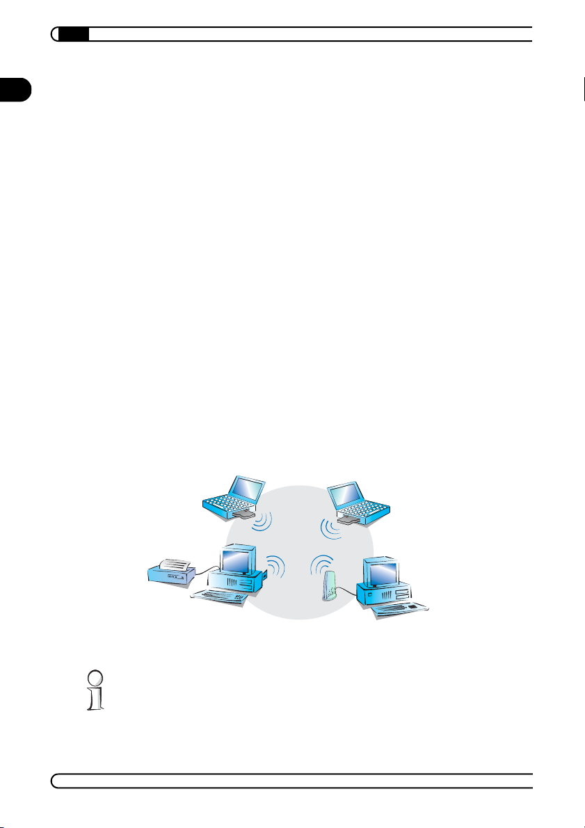
1.3.1 Ad-hoc network. . . . . . . . . . . . . . . . . . . . . . . . . . . . . . . . . . . . . . . . . . . . . . . . . 8
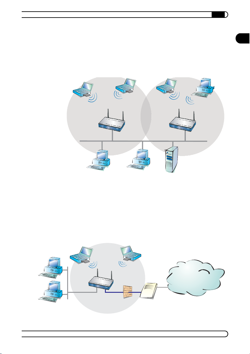
1.3.2 Infrastructure network . . . . . . . . . . . . . . . . . . . . . . . . . . . . . . . . . . . . . . . . . . . 9
1.4 Standardized radio transmission by IEEE . . . . . . . . . . . . . . . . . . . . . . . . . . . . . . . . . 10
1.5 The AirLancer 54 models . . . . . . . . . . . . . . . . . . . . . . . . . . . . . . . . . . . . . . . . . . . . . 12
1.5.1 Encryption in three security steps. . . . . . . . . . . . . . . . . . . . . . . . . . . . . . . . . . 12
1.6 The next chapters . . . . . . . . . . . . . . . . . . . . . . . . . . . . . . . . . . . . . . . . . . . . . . . . . . . 13
2 AirLancer MC-54 . . . . . . . . . . . . . . . . . . . . . . . . . . . . . . . . . . . . . . . . . . . . . . . . . . . . . . . . . 15
2.1 Properties . . . . . . . . . . . . . . . . . . . . . . . . . . . . . . . . . . . . . . . . . . . . . . . . . . . . . . . . . 15
2.2 Package contents . . . . . . . . . . . . . . . . . . . . . . . . . . . . . . . . . . . . . . . . . . . . . . . . . . . 15
2.3 Have a look at the card. . . . . . . . . . . . . . . . . . . . . . . . . . . . . . . . . . . . . . . . . . . . . . . 15
2.4 Installation . . . . . . . . . . . . . . . . . . . . . . . . . . . . . . . . . . . . . . . . . . . . . . . . . . . . . . . . 16
2.4.1 Checking the system preconditions . . . . . . . . . . . . . . . . . . . . . . . . . . . . . . . . 16
2.4.2 Putting the card into your PC . . . . . . . . . . . . . . . . . . . . . . . . . . . . . . . . . . . . . 17
2.4.3 Driver installation for AirLancer MC-54 . . . . . . . . . . . . . . . . . . . . . . . . . . . . . 17
3 AirLancer PCI-54 . . . . . . . . . . . . . . . . . . . . . . . . . . . . . . . . . . . . . . . . . . . . . . . . . . . . . . . . . 19
3.1 Properties . . . . . . . . . . . . . . . . . . . . . . . . . . . . . . . . . . . . . . . . . . . . . . . . . . . . . . . . . 19
3.2 Package contents . . . . . . . . . . . . . . . . . . . . . . . . . . . . . . . . . . . . . . . . . . . . . . . . . . . 19
3.3 Have a look at the card. . . . . . . . . . . . . . . . . . . . . . . . . . . . . . . . . . . . . . . . . . . . . . . 19
3.4 Installation . . . . . . . . . . . . . . . . . . . . . . . . . . . . . . . . . . . . . . . . . . . . . . . . . . . . . . . . 20
3.4.1 Checking the system preconditions . . . . . . . . . . . . . . . . . . . . . . . . . . . . . . . . 20
3.4.2 Installing AirLancer PCI-54 . . . . . . . . . . . . . . . . . . . . . . . . . . . . . . . . . . . . . . . 21
3.4.3 Driver installation for AirLancer PCI-54 . . . . . . . . . . . . . . . . . . . . . . . . . . . . . 22
4 The AirLancer Client Manager . . . . . . . . . . . . . . . . . . . . . . . . . . . . . . . . . . . . . . . . . . . . . 23
4.1 Starting the AirLancer AirLancer Client Manager . . . . . . . . . . . . . . . . . . . . . . . . . . 24
4.2 Basic configuration. . . . . . . . . . . . . . . . . . . . . . . . . . . . . . . . . . . . . . . . . . . . . . . . . . 24
4.3 Overview of the functions . . . . . . . . . . . . . . . . . . . . . . . . . . . . . . . . . . . . . . . . . . . . 27
4.3.1 Administration of profiles . . . . . . . . . . . . . . . . . . . . . . . . . . . . . . . . . . . . . . . . 27
4.3.2 Configuration. . . . . . . . . . . . . . . . . . . . . . . . . . . . . . . . . . . . . . . . . . . . . . . . . . 27

|
|AirLancer |
6
EN
4.3.3 Analysis, diagnosis and information. . . . . . . . . . . . . . . . . . . . . . . . . . . . . . . . 27
4.4 Encryption settings . . . . . . . . . . . . . . . . . . . . . . . . . . . . . . . . . . . . . . . . . . . . . . . . . . 28
4.4.1 General rules for WEP keys . . . . . . . . . . . . . . . . . . . . . . . . . . . . . . . . . . . . . . 28
4.4.2 Valid key characters . . . . . . . . . . . . . . . . . . . . . . . . . . . . . . . . . . . . . . . . . . . . 28
4.4.3 Sliding key change . . . . . . . . . . . . . . . . . . . . . . . . . . . . . . . . . . . . . . . . . . . . . 29
5 Configuration example . . . . . . . . . . . . . . . . . . . . . . . . . . . . . . . . . . . . . . . . . . . . . . . . . . . . 31
5.1 Connecting to a company network. . . . . . . . . . . . . . . . . . . . . . . . . . . . . . . . . . . . . . 31
6 Extension of the LANCOM 3000 Wireless base station . . . . . . . . . . . . . . . . . . . . . . . . 35
7 Security within the Wireless LAN . . . . . . . . . . . . . . . . . . . . . . . . . . . . . . . . . . . . . . . . . . 37
7.1 Closed network. . . . . . . . . . . . . . . . . . . . . . . . . . . . . . . . . . . . . . . . . . . . . . . . . . . . . 37
7.2 Access control via MAC address . . . . . . . . . . . . . . . . . . . . . . . . . . . . . . . . . . . . . . . 37
7.3 Encryption of the data transfer (WEP) . . . . . . . . . . . . . . . . . . . . . . . . . . . . . . . . . . . 38
7.3.1 WEP functionality . . . . . . . . . . . . . . . . . . . . . . . . . . . . . . . . . . . . . . . . . . . . . . 38
7.3.2 Tipps for handling keys . . . . . . . . . . . . . . . . . . . . . . . . . . . . . . . . . . . . . . . . . . 39
7.3.3 The ways you can increase the security additionally. . . . . . . . . . . . . . . . . . . 39
7.4 802.1x / EAP . . . . . . . . . . . . . . . . . . . . . . . . . . . . . . . . . . . . . . . . . . . . . . . . . . . . . . . 40
7.5 IPSec over WLAN . . . . . . . . . . . . . . . . . . . . . . . . . . . . . . . . . . . . . . . . . . . . . . . . . . . 40
8 Appendix . . . . . . . . . . . . . . . . . . . . . . . . . . . . . . . . . . . . . . . . . . . . . . . . . . . . . . . . . . . . . . . . 41
8.1 Technical data . . . . . . . . . . . . . . . . . . . . . . . . . . . . . . . . . . . . . . . . . . . . . . . . . . . . . 41
8.2 Radio channels . . . . . . . . . . . . . . . . . . . . . . . . . . . . . . . . . . . . . . . . . . . . . . . . . . . . . 42
8.2.1 Radio channels in the 2,4 GHz frequency band . . . . . . . . . . . . . . . . . . . . . . . 42
8.2.2 Radio channels in the 5 GHz frequency band . . . . . . . . . . . . . . . . . . . . . . . . . 43
8.3 Restrictions of use within EU . . . . . . . . . . . . . . . . . . . . . . . . . . . . . . . . . . . . . . . . . . 44
8.4 Declaration of conformity. . . . . . . . . . . . . . . . . . . . . . . . . . . . . . . . . . . . . . . . . . . . . 46
8.4.1 European Union (CE) . . . . . . . . . . . . . . . . . . . . . . . . . . . . . . . . . . . . . . . . . . . . 46

|Introduction 7
|AirLancer |
EN
1 Introduction
The advantages of a radio network (Wireless LAN) are obvious: notebooks
and PCs can be set up where they are needed. Due to Wireless LANs, prob-
lems with missing connections or structural alterations belong to the past.
Network access in conferences or during presentations, access to resources
in neighbouring buildings or data exchange with portable terminals are only
some possible applications of Wireless LANs.
1.1 What is a Wireless LAN?
A Wireless LAN connects single terminals (e.g. PCs, notebooks and PDAs) to
a local network (also LAN – Local Area Network). In contrast to a conven-
tional LAN, communication takes place via radio links rather than via network
cables. This is the reason why a Wireless LAN is also called Wireless Local
Area Network (WLAN).
All functions of a cable-bound network are also available in a Wireless LAN:
access to files, servers, printers etc. is as possible as the connection of indi-
vidual stations to an internal mail system or to the Internet access.
1.2 What do you need for a Wireless LAN?
The obvious advantages of the Wireless LANs raise questions about the
required hardware equipment.
1.2.1 Radio interfaces to the network
Each device within a Wireless LAN needs a radio interface to be able to
access the Wireless LAN. Many devices, which do not have a radio interface
as standard, can be upgraded with an extension card or an adapter. With an
AirLancer client adapter you upgrade a device for access to the Wireless
LAN.
A Wireless LAN is made of at least two devices having each a radio interface.
In this case, these two devices are able to communicate directly via radio.

Introduction |
|AirLancer |
8
EN
1.2.2 Central collecting point – the base station
With an additional base station, a Wireless LAN becomes more comfortable
and more efficient. The base station (access point) enables a central admin-
istration of the Wireless LAN. Furthermore, with a base station you can also
connect an entire cable-bound LAN to a Wireless LAN. If the base station
contains a router, too, it can make available a ISDN or DSL a connection to
the Internet as well.
According to whether a base station is used or not in the Wireless LAN, two
different operation modes arise for a Wireless LAN: on the one hand the
ad-hoc-network (peer-to-peer), on the other the infrastructure-network
(access point).
1.3 Operation modes
We take now a separate look at both operation modes.
1.3.1 Ad-hoc network
In ad-hoc networks you connect two or more PCs with own wireless inter-
faces directly together to build a Wireless LAN. All stations in this wireless
LAN are able to communicate between each other without any further equip-
ment.
Ad-hoc-network This operation mode is generally called peer-to-peer network (spontaneous
network). PCs can immediately get in touch and exchange data.
Ad-hoc-networks are only possible in the 2,4 GHz frequency band with
radion-LANs according to IEEE 802.11g and IEEE 802.11b. Ad-hoc-networks
are not possible in the 5 GHz frequency band according to the IEEE 802.11a
standard.
ad-hoc-network

|Introduction 9
|AirLancer |
EN
1.3.2 Infrastructure network
A base station (access point) is needed for connection to an existing network.
The base station forms the control center for data exchange within the
WLAN. The base station additionally can offer - depending on its product type
- access to a cable-based LAN, as well as to the Internet.
Infrastructure-
network A Wireless LAN with one or more base stations is generally called a
peer-to-LAN-network. In Wireless LAN terminology this network topology is
referred to as an infrastructure-network. Depending on its product type, LAN-
COM Wireless base stations contain integrated routers for the connection
with ISDN or DSL. Via the integrated routing function the linked stations get
thus access to Internet and ISDN. Simultaneously, the router’s integrated
Firewall ensures an optimal security of the network.
Internet
DSL/cable modem
Firewall

Introduction |
|AirLancer |
10
EN
An infrastructure-network is excellently suitable as an extension to existing
wired LANs. For extension of a LAN in areas, where a wiring is not possible
or uneconomical, the infrastructure-network represents an ideal alternative.
1.4 Standardized radio transmission by IEEE
IEEE 802.11 AirLancer client adapters work with the IEEE 802.11 standard. This standard
family represents an extension of the already existing IEEE standards for
LANs, of which IEEE 802.3 for Ethernet is the most popular one. Within the
IEEE 802.11 family there exist different standards for the radio transmission
in different frequency ranges and with different speeds. AirLancer client
adapters support according to their respective type the IEEE 802.11b standard
with up to 11Mbps transfer rate into 2,4 GHz frequency band, the IEEE
802.11g standard with up to 54 Mbps transfer rate in the 2,4 GHz frequency
band, and the 802.11a standard with up to 54 Mbps transfer rate in the 5 GHz
frequency band.
IEEE 802.11a
54 Mbps
IEEE 802.11a describes the operation of Wireless LANs in the 5 GHz fre-
quency band (5,15 GHz to 5,75 GHz) with up to 54 Mbps maximum transfer
rate. The real throughput depends however on the distance and/or on the
quality of the connection. With increasing distance and diminishing connect-
ing quality, the transmission rate lowers to 48 Mbps, afterwards to 36 Mbps
etc., up to a minimum of 6 Mbps. The distance of transmission ranges from
up to 125 m in open expanses, in buildings typically up to 25 m. The IEEE
802.11a standard uses OFDM (Orthogonal Frequency Division Multiplexing)
as modulation scheme.
Please notice that not all frequencies are permitted in each country! You will
find a table with the allotted frequencies and the permission regulations in
the appendix.
OFDM In the 5 GHz frequency band, the OFDM modulation scheme is used for IEEE
802.11a. OFDM is a modulation scheme, which utilizes multiple independent
carrier frequencies for the signal transmission, and which modulates these
multiple carriers each with a reduced data transfer rate. Thus the OFDM mod-
ulation scheme is very insensitive in particular to echoes and other impair-
ments and enables high data transfer rates.
IEEE 802.11b
11 Mbps
IEEE 802.11b describes the operation of local Wireless LANs in the ISM fre-
quency band (Industrial, Scientific, Medical: 2.4 up to 2.483 GHz). The maxi-
mum transfer rate is up to 11 Mbps. The real throughput depends however on

|Introduction 11
|AirLancer |
EN
the distance and/or on the quality of the connection. With increasing dis-
tance and diminishing connecting quality the transmission rate lowers to 5,5
Mbps, afterwards to 2 and finally to 1 Mbps. The range of the transmission
distances is between up to 150 m in open expanses and in buildings typically
up to 30 m. Due to different frequency bands in use, IEEE 802.11b is not com-
patible to IEEE 802.11a.
Please notice that not all frequencies are permitted in each country! You will
find a table with the allotted frequencies and the permission regulations in
the appendix.
DSSS For shielding against interferences by other transmitters, which have possibly
the same frequency band, the DSSS procedure (Direct Sequence Spread
Spectrum) is used for IEEE 802.11b in the 2,4 GHz frequency band. A trans-
mitter normally uses only a very narrow range of the available frequency band
for transmission. If exactly this range is used by another transmitter, interfer-
ences in transmission would be the result. With the DSSS procedure the
transmitter uses a broader spread of the possible frequencies and becomes
more insensitive to narrow-band disturbances then. This procedure is also
used in military range for increasing tap-proof security.
IEEE 802.11g
54 Mbps The IEEE 802.11g standard works likewise with up to 54 Mbps data transmis-
sion rate in the 2,4 GHz frequency band. Contrary to IEEE 802.11b, the OFDM
modulation is used for IEEE 802.11g like already introduced for IEEE 802.11a.
IEEE 802.11g contains a special compatibility mode that ensures a downward
compatibility to the popular IEEE 802.11b standard . However, in this compat-
ibility mode you encounter reduced transmission speeds. Due to the different
frequency bands, IEEE 802.11g can not be compatible to IEEE 802.11a. The
transmission distances of IEEE 802.11g products are comparable with those
of IEEE 802.11b products.
Transfer rates The indicated transfer rates are always to interpret as gross data rates, i.e.
that the entire protocol overhead - as for example the complex protocols to
secure the radio transmission - are included in the indicated transfer rates.
The net data transfer rate can be thus lower than the indicated gross data
rates, typically over up to the half for all IEEE 802.11 standards mentioned
above.
Ranges The actually obtained distances for radio transfers depend strongly on the
individual spatial environment. In particular influences of noise and obstacles

Introduction |
|AirLancer |
12
EN
have an effect on the range. Decisive is frequently an optimal placement of
the radio stations (both network adapters and base stations).
1.5 The AirLancer 54 models
The AirLancer series with 54 Mbps data transfer rate features several mod-
els. You have the possibilty to extend standard PCs and a multitude of mobile
computers for access to the Wireless LAN:
•AirLancer MC-54ag
Dual band PC card (Cardbus) according either to IEEE 802.11a (up to 54
Mbps data tranfer rate in the 5 GHz band) or to IEEE 802.11g (up to 54
Mbps data transfer rate in 2,4 GHz, backward-compatible to IEEE
802.11b) for operation with mobile devices
•AirLancer MC-54g
PC card (Cardbus) according to IEEE 802.11g (up to 54 Mbps data tranfer
rate in 2,4 GHz, backward-compatible to IEEE 802.11b) for operation with
mobile devices
•AirLancer PCI-54ag
Dual band PCI adapter according to IEEE 802.11a (up to 54 Mbps data
tranfer rate into 5 GHz frequency band) or IEEE 802.11g (up to 54 Mbps
data tranfer rate into 2,4 GHz frequency band, backward-compatible to
IEEE 802.11b) for installation in a stationary desktop PC. You find an
external dual band antenna enclosed with the product.
1.5.1 Encryption in three security steps
Several countries regulate the operation of encryption technologies. Air-
Lancer 54 Mbps Wireless LAN adapters support three different variants of
encryption:
•WEP64 – for encryption in accordance with Wired Equivalent Privacy
(WEP), encryption keys are used with an effective length of 40 bit.
•WEP128 – encryption keys with a length of 104 bit.
•WEP152 – operate with keys with a length of 128 bit (only applicable
with AirLancer 54 Mbps cards).
Please inform yourself about the valid legal regulations for employment of
encryption technology in the country you want to use a AirLancer Wireless
LAN adapter. Pay attention to use no devices which support inadmissible
encryption technologies.

|Introduction 13
|AirLancer |
EN
For detailed information about the operation of WEP encryption please see
’Encryption of the data transfer (WEP)’ on page 38.
1.6 The next chapters
In the following two chapters you will find detailed descriptions and installa-
tion instructions for the AirLancer variants. Each AirLancer type has got its
own chapter. You may advance straight forward to your model’s chapter.
•AirLancer MC-54: chapter 2 on page 15.
•AirLancer PCI-54: chapter 3 on page 19.
The remaining parts of the documentation from chapter 4 upwards are valid
for all AirLancer again.

Introduction |
|AirLancer |
14
EN

|AirLancer MC-54 15
|AirLancer |
EN
2AirLancer MC-54
In this chapter you will find a description of the AirLancer MC-54 and a
step-by-step instruction for starting the card. After installation of hardware,
drivers and the AirLancer software, you have to set up the access to a Wire-
less LAN. The description of this configuration step can be found for both Air-
Lancers in chapter 5.
2.1 Properties
AirLancer MC-54ag is compliant to the IEEE 802.11a, IEEE 802.11g and IEEE
802.11b standards, and is thus excellent suitable for notebook users who
need a maximum of flexibility and performance. The switch between the
radio standards can be made as desired automatically, and enables at any
time the fastest possible connection. So for example the connection to a com-
pany network with up to 54 Mbps can be made with the IEEE 802.11g or IEEE
802.11a standard, while on journeys the compatibility to public hot spots is
ensured with up to 11 Mbps transfer rate according to IEEE 802.11b.
AirLancer MC-54g complies to the IEEE 802.11g standard with up to 54 Mbps
data transfer rate, as well as to the 11 Mbps IEEE 802.11b standard.
2.2 Package contents
Please check the package contents for completeness before starting. The
package should contain the following components:
•AirLancer MC-54ag or AirLancer MC-54g
•AirLancer 54 MBit-CD with drivers, the Client Manager and electronical
documentation
If anything is missing, please contact your retailer directly.
2.3 Have a look at the card
The radio network card AirLancer MC-54 is a PC card for notebooks and
mobile devices with Cardbus interface. It is a little bit longer than other PC
cards. The internal radio antenna of the AirLancer MC-54 is located inside the
part jutting out of the casing.

AirLancer MC-54 |
|AirLancer |
16
EN
1 Cardbus receptacle
2 LEDs for sending and receiving status:
•Off – no radio activity
•Blinking alternately – searching for base station
•Blinking simultaneously – sending or receiving of radio data
•Flickering – card is in power save mode
3 Integrated antenna
2.4 Installation
The installation of AirLancer MC-54 takes place in four steps:
a Check the system preconditions
b Put the AirLancer MC-54 into your PC
c Driver installation
d Setting up for accessing the Wireless LAN – you will find the instruction
for this configuration step in chapter 4 ’The AirLancer Client Manager’ on
page 23.
2.4.1 Checking the system preconditions
You should check before installing, whether your device fulfills all necessary
system preconditions:
•PC with a free PC card interface (Cardbus, type II or type III), 300 MHz pro-
cessor or faster, at least 32 MByte RAM.
•CD ROM drive
3
21

|AirLancer MC-54 17
|AirLancer |
EN
•One of the following operating systems:
•Windows 98 SE (Second Edition)
•Windows ME (Millennium Edition)
•Windows 2000
•Windows XP
2.4.2 Putting the card into your PC
Slip the card into a free PC card slot of your computer while running. Ensure
that the side with the product label points upwards and the side with the
series number label downwards.
2.4.3 Driver installation for AirLancer MC-54
In the course of the plug&play hardware identification of Windows ME, Win-
dows 98 SE, Windows XP and Windows 2000, you will see that your compu-
ter identifies the new hardware automatically, just a short time after
insertion of the card.
Please follow the instructions of the hardware installation wizard, and point
to the AirLancer 54 MBit-CD when searching for drivers.
You find the appropriate drivers in the root folder of your AirLancer 54
MBit-CD.

AirLancer MC-54 |
|AirLancer |
18
EN

|AirLancer PCI-54 19
|AirLancer |
EN
3AirLancer PCI-54
In this chapter you will find a description of the radio network card AirLancer
PCI-54 and a step-by-step instruction for starting it. This chapter will end with
the successful installation of hardware and drivers. The following configura-
tion of the access to a Wireless LAN is described in chapter 5.
3.1 Properties
AirLancer PCI-54ag is intended for operating in a stationary desktop PC. It is
working compliant to the IEEE 802.11a standard with up to 54 Mbps in the 5
GHz frequency band, and compliant to the IEEE 802.11g standard with up to
54 Mbps in the 2,4 GHz frequency band. AirLancer PCI-54ag is additionally
backward-compatible to the IEEE 802.11b standard. Optimum transfer results
are achieved due to the enclosed external antenna, which is suitable for ope-
ration in 2,4 GHz as well as in 5 GHz bands.
3.2 Package contents
Please check the package contents for completeness before starting. The
package should contain the following components:
•PCI-radio network card AirLancer PCI-54ag
•AirLancer 54 MBit-CD with drivers, the Client Manager and electronical
documentation
•External dual-band antenna
If anything is missing, please contact your retailer directly.
3.3 Have a look at the card
AirLancer PCI-54 is intended for the installation in a desktop PC. An external
antenna is part of the package contents.

AirLancer PCI-54 |
|AirLancer |
20
EN
1AirLancer PCI-54
2 External antenna (The kind of the external antenna may vary from the
illustation above.)
3 Connection for external antenna
4 Plug-in socket for PCI bus
3.4 Installation
The installation of AirLancer PCI-54 takes place in five steps:
a Checking the system preconditions
b Hardware installation of the AirLancer PCI-54
c Connection of the external antenna
d Driver installation
e Settings for access to the Wireless LAN – you will find the instruction for
this configuration in chapter 4 ’The AirLancer Client Manager’ on
page 23.
3.4.1 Checking the system preconditions
You should check before installing, whether your device fulfills all necessary
system preconditions:
2
3
1
4
This manual suits for next models
1
Table of contents
Other Lancom Network Router manuals

Lancom
Lancom LC-1823 User manual

Lancom
Lancom GS-1224 User manual

Lancom
Lancom 1723 VOIP User manual

Lancom
Lancom 1811 User manual

Lancom
Lancom 850 UMTS User manual

Lancom
Lancom 1722 VOIP User manual

Lancom
Lancom AP-321-3G User manual

Lancom
Lancom 1781VAW User manual

Lancom
Lancom 800+ User manual

Lancom
Lancom 9100 VPN User manual

Lancom
Lancom GS-2310P User manual

Lancom
Lancom 1821n Wireless User manual

Lancom
Lancom OAP-321-3G User manual

Lancom
Lancom 1781VAW User manual

Lancom
Lancom 1721+ VPN Manual

Lancom
Lancom 1781VA User manual

Lancom
Lancom 1783VA-4G User manual

Lancom
Lancom L-54g Wireless User manual

Lancom
Lancom 1780EW-3G User manual

Lancom
Lancom 821 User manual