Land Instruments International SYSTEM 4 M1 600/1600C L User manual

Part Nº 198.002 [Publication Nº S4980060]
Issue D 12/02
Installation Guide
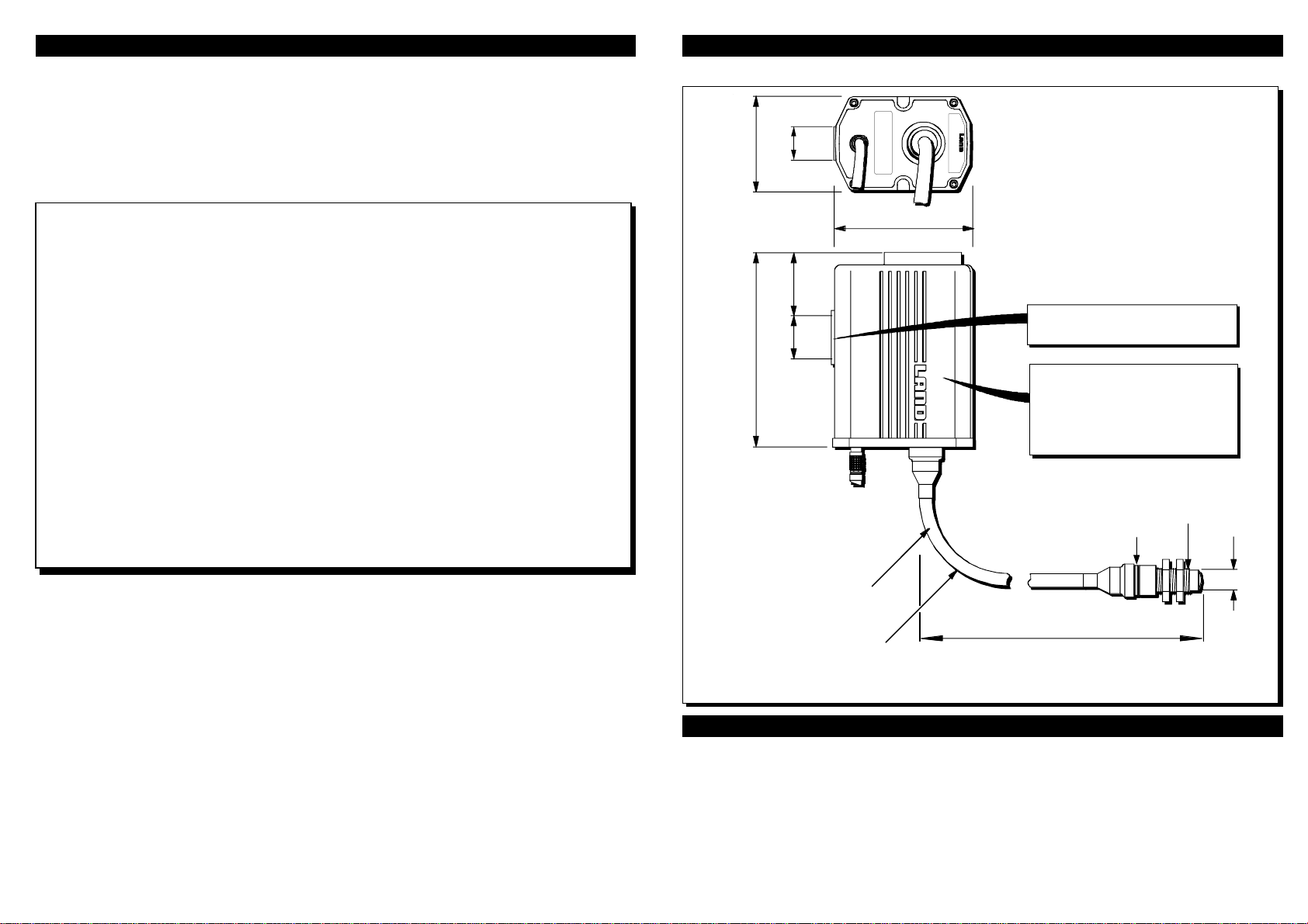
Fibroptic Thermometer
Summary Specification
M1600/1600CL M1800/2600CL M2300/1100CL M350/250CQ R1600/1600CL R11000/2600CL
M11100/2900FL M11500/4700FL M2600/2000FL M3150/500FQ R11100/2900FL R11800/4700FL
Temp.range: 600to1600°C 800to2600°C 300to1100°C 50to250°C 600to1600°C 1000to2600°C
1100to2900°F 1500to4700°F 600to2000°F 150to500°F 1100to2900°F 1800to4700°F
Wavelength: 1µm 1.6µm 2.1µm 0.85to1.1µm
Responsetime: 5ms (0 to 95%) <100ms(0to95%) 15ms (0 to95%)
Fieldofview: 25:1 75:1 25:1 20:1 25:1 75:1
(nominal):
Targetdiameter:
A,D10optichead: 4mm(0.15in) 1.3mm(0.05in) 4mm(0.15in) 5mm(0.2in) 4mm(0.15in) 1.3mm(0.05in)
at100mm(3.9in) at100mm(3.9in) at100mm(3.9in) at100mm(3.9in) at100mm(3.9in) at100mm(3.9in)
A,D25optichead: 10mm(0.39in) 3.3mm(0.12in) 10mm(0.39in) 12.5mm(0.5in) 10mm(0.39in) 3.3mm(0.12in)
at250mm(9.8in) at250mm(9.8in) at250mm(9.8in) at250mm(9.8in) at250mm(9.8in) at250mm(9.8in)
A,D50optichead: 23mm(0.90in) 6.7mm(0.26in) 23mm(0.90in) 25mm(1.0in) 23mm(0.90in) 6.7mm(0.26in)
at500mm(19.6in) at500mm(19.6in) at500mm(19.6in) at500mm(19.6in) at500mm(19.6in) at500mm(19.6in)
Accuracy
Repeatability: <1°C(2°F) <2°C(4°F) <1°C(2°F) 1K <1°C(2°F) <2°C(4°F)
Absolute: <0.4%K <0.7%K <0.25%+1K <3K <0.65%K <1.1%K
StabilityTemp: 0.2°/°ambient 0.3°/°ambient 0.2°/°ambient 0.1°/°ambient 0.05%/°ambient 0.05%/°ambient
StabilityTime: <2°C(4°F)per year
Vibration 3G, any axis, 10 to 300Hz
Humidity 0to 99%noncondensing
Sealing IP65
Ambienttemp.
Optichead: 200°C(392°F) 150°C(302°F) 200°C(392°F)
Lightguide: 200°C(392°F) 150°C(302°F) 200°C(392°F)
Detector
Specified: 0to70°C 0to50°C 0to70°C
(32to158°F) (32to122°F) (32to158°F)
Operating: -10to60°C 0to50°C -10to60°C
(14to140°F) (32to122°F) (14to140°F)
CE: EN50-082-2(immunity),EN50-081-1(emission),IEC1010(safety)
© Land Instruments International, 2002
Land Instruments International
Dronfield S18 1DJ
England
Telephone: (01246) 417691
Facsimile: (01246) 410585
Email:[email protected]
Internet: www.landinst.com
Land Instruments International
10 Friends Lane
Newtown PA 18940-1804 U.S.A.
Telephone: (215) 504 8000
Facsimile: (215) 504 0879
Email: [email protected]
Internet: www.landinstruments.net

InstallationDimensions
Installation Accessories
For installation in hostile environments, the Land System 4 Protection Jacket is designed for
use with the thermometer and there is a range of Air Purges & Mounting accessories available
for use with the optic head.
Aboutthisguide
This guide gives the basic information necessary to install a Land System 4 Fibroptic
thermometer and get it working. More detailed information is contained in the 'User Guide'.
Informationregardingtherepairandcalibrationofthethermometeriscontainedinthe'Service
Manual'.
It is important to check the equipment with which you have been supplied to ensure that all
ordered items and accessories have been delivered.
NOTES
If the thermometer is to be used in an area of ambient temperature higher
than that specified as safe for the thermometer, then the thermometer
mustbehousedinaspecialcoolingjacketavailablefromLandInstruments
International.
Ifthe thermometer is tobe used in anarea where the atmospherecontains
a high proportion of dust/smoke/steam etc, then the optic head must be
used in conjunction with a special air purge to keep the lens clean. The
air purge is available from Land Instruments International.
To prevent any possibility of water ingress into the electronics/detector
module, the thermometer must be orientated as shown in the 'Installation
Dimensions' diagram.
For more information on cooling jackets and air purges, refer to the
Installation Guides supplied with those products.
25/ 1.0 54.5/ 2.15
158/6.22
114/4.49
25/0.98
80.5/3.17
Minimum bend
Light guide length
All dimensions in millimetres/inches
SERIAL No.
TYPE:
18/0.71
L10/Q10 = 1000/39.37
L20/Q20 = 2000/78.74
L35/Q35 = 3500/137.80
radius 50/1.97
ingress
Recommended orientation of
thermometer to prevent
of water, and build up of dirt etc.
on electrical and lightguide
connectors
Mounting pad - 2 holes ¼" BSW
7/0.3 deep on 25/ 1.0 centres
Spacer
thread
M22 x 1.5
Approx. 160/6.30
required for optic head removal

Mounting Pad (Tripod Mounting)
2 holes, ¼" BSW, 7mm (0.28in) deep on
25mm (0.98in) centres
View on Bottom
View on Side View on Rear
Electrical Connection
Align the two red markers (i.e. align the lugs
on the plug of the pre-wired cable with the
keyway in the connector on the thermometer).
Push the plug into the connector.
Keyway
Lugs
Markers
Lightguide
Ensure that the lightguide is not subjected to
tension or other undue force.
Minimum bend radius = 50mm (2.0in)
Laser Alignment Unit (optional)
Press button to illuminate target area with laser
light from optic head. Adjust the thermometer
mounting until optic head is aligned on required
target.
Refer to User Guide for full instructions.
View on Front
Locking Sleeve
Cable Schedule
1
2
3
4
5
6
7
Yellow
Blue
White
Screen
Red
Black
Green
FunctionCable Colour
T+
T-
E+
Screen
V+
V-
E-
Processor
Pin Nº
NOTE
The thermometer body must be earthed
electrically via it's mountings
FOT010098
15.0mm
0.59in 12.3mm
0.48in 9.5mm
0.37in 6.8mm
0.27in 4.0mm
0.16in 8.8mm
0.35in
0mm
0in 25mm
0.98in 50mm
1.97in 75mm
2.95in 100mm
3.94in 125mm
4.92in
Target diameter
Tar
g
et distance Optic Head A10, Field of View 25:1 (Red spacer)
14.3mm
0.56in 11.1mm
0.44in 7.8mm
0.31in 4.6mm
0.18in 1.3mm
0.05in 5.2in
0.20in
0mm
0in 25mm
0.98in 50mm
1.97in 75mm
2.95in 100mm
3.94in 125mm
4.92in
Target diameter
Tar
g
et distance Optic Head A10, Field of View 75:1 (Red spacer)
Optic Head A25, Field of View 25:1 (Blue spacer)
0mm
0in 50mm
1.97in 100mm
3.94in 200mm
7.87in 250mm
9.84in 300mm
11.81in
Target diameter
Tar
g
et distance
150mm
5.91in
11.2mm
0.44in 11.0mm
0.43in 10.7mm
0.42in 10.2mm
0.40in 10.0mm
0.39in 14.2mm
0.56in
10.5mm
0.41in
Optic Head A25, Field of View 75:1 (Blue spacer)
0mm
0in 50mm
1.97in 100mm
3.94in 200mm
7.87in 250mm
9.84in 300mm
11.81in
Target diameter
Tar
g
et distance
150mm
5.91in
11.0mm
0.43in 9.5mm
0.37in 7.9mm
0.31in 4.8mm
0.19in 3.3mm
0.13in 6.2mm
0.24in
6.4mm
0.25in
Optic Head A50, Field of View 25:1 (No spacer)
Target diameter
10.3mm
0.41in 12.8mm
0.50in 15.4mm
0.61in 20.5mm
0.81in 23.0mm
0.91in 26.1mm
1.03in
17.9mm
0.70in
0mm
0in 100mm
3.94in 200mm
7.87in 400mm
15.75in 500mm
19.69in 600mm
23.62in
Tar
g
et distance
300mm
11.81in
Optic Head A50, Field of View 75:1 (No spacer)
Target diameter
10.1mm
0.38in 9.4mm
0.37in 8.7mm
0.34in 7.4mm
0.29in 6.7mm
0.26in 10.1mm
0.38in
8.1mm
0.32in
0mm
0in 100mm
3.94in 200mm
7.87in 400mm
15.75in 500mm
19.69in 600mm
23.62in
Tar
g
et distance
300mm
11.81in
TARGET SIZE TABLES - FIBROPTIC M1 AND M2 TARGET SIZE TABLES - FIBROPTIC M3
15.9mm
0.63in 13.2mm
0.52in 10.5mm
0.41in 7.7mm
0.30in 5.0mm
0.20in 10.2mm
0.40in
0mm
0in 25mm
0.98in 50mm
1.97in 75mm
2.95in 100mm
3.94in 125mm
4.92in
Target diameter
Tar
g
et distance Optic Head D10, Field of View 20:1 (Green spacer)
0mm
0in 50mm
1.97in 100mm
3.94in 200mm
7.87in 250mm
9.84in 300mm
11.81in
Target diameter
Tar
g
et distance
150mm
5.91in
13.7mm
0.54in 13.5mm
0.53in 13.2mm
0.52in 12.7mm
0.50in 12.5mm
0.49in 17.7mm
0.70in
13.0mm
0.51in
Optic Head D25, Field of View 20:1 (Purple spacer)
Target diameter
13.0mm
0.51in 15.4mm
0.61in 17.8mm
0.70in 22.6mm
0.89in 25.0mm
0.98in 32.6mm
1.28in
20.2mm
0.80in
0mm
0in 100mm
3.94in 200mm
7.87in 400mm
15.75in 500mm
19.69in 600mm
23.62in
Tar
g
et distance
300mm
11.81in
Optic Head D50, Field of View 20:1 (No spacer)
INSTALLATIONINFORMATION
This manual suits for next models
11
Other Land Instruments International Thermometer manuals