Land Pride L02 User manual

1
© Copyright 2022 Printed
For L3302 & L3902 Kubota Tractors with
LA526 Loader
Before You Start
General Information
Your L02 Third Function Valve Kit has been designed for
the L3302 and L3902 Kubota ROPS tractors equipped
with a Kubota LA526 front loader. These assembly
instructions apply to the Third Function Valve Kit
Accessories listed below:
•380-362A: 3FVK PC FLE68ABD ROPS . . . . . . page 2
•380-363A: 3FVK FF FLE68ABD ROPS. . . . . . . page 2
Further Assistance
Your Land Pride dealer wants you to be satisfied with your
new L02 Third Function Valve Kit. If for any reason you do
not understand any part of this manual or are not
satisfied with the service received, the following actions
are suggested:
1. Discuss any problems you have with your Third
Function Valve Kit with your dealership service
personnel so they can address the problem.
2. If you are still not satisfied, seek out the owner or
general manager of the dealership, explain the
question/problem, and request assistance.
3. For further assistance write to:
Land Pride Service Department
1525 East North Street
P.O. Box 5060
Salina, Ks. 67402-5060
E-mail address
lpservicedept@landpride.com
When you see this symbol, the subsequent
instructions and warnings are serious - follow
without exception. Your life and the lives of others
depend on it!
!
WARNING: Cancer and reproductive harm.
www.P65Warnings.ca.gov
California Proposition 65
!
IMPORTANT: Before you begin, read these
instructions and check to be sure all parts and tools
are accounted for. Please retain these installation
instructions for future reference and parts ordering
information.
Assembly Instructions
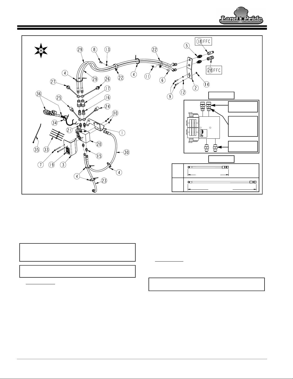
A detailed listing of parts for your ROPS tractor Third
Function Valve Kit is provided on page 15 for kits using
pioneer couplers, and page 17 for kits using flat-face
couplers. Use the list that is for your specific Third
Function Valve Kit as a checklist to inventory parts
received. Manuals can also be downloaded free of
charge from our website at www.landpride.com.
Please contact your local Land Pride dealer for any
missing hardware.
Direction Reference
All directional references are made from the operator
seat while facing the direction the machine will operate.
Directional Arrows Used in Illustrations
Initial Preparations
CAUTION
!
To avoid minor or moderate injury:
Hydraulic fluid and components that the fluid flows through
such as couplers, hoses, hydraulic lines, fittings and motor
become hot from use. Be careful when connecting and
disconnecting couplers. It is best to wear gloves and to allow
hydraulic fluid and hydraulic components to cool before
touching them.
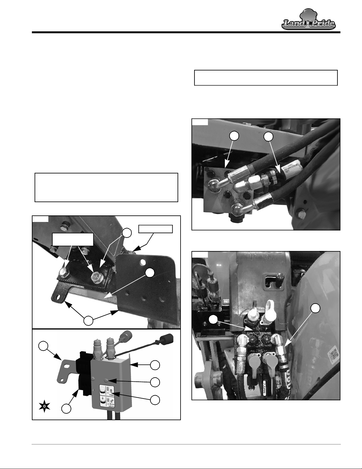
The steps listed below must be followed before installing
this kit:
1. If attached, dismount loader from tractor. If loader is
not attached, skip to step 5.
2. Turn tractor off, then relieve all hydraulic pressure
from hydraulic lines by operating the loader control
lever in all directions. Proceed with locking the control
lever before dismounting.
3. Disconnect loader hydraulic lines from loader valve.
a. Refer to your tractor/loader Operator’s Manual for
additional unhooking instructions.
4. Restart tractor and slowly back away from loader.
5. Park tractor on a flat, level surface. Put tractor in park
or set park brake, turn off engine, and remove ignition
key to prevent unauthorized starting.
6. As a safety precaution, disconnect the negative (-)
battery cable from battery terminal. Move cable away
from terminal to avoid accidental contact.
U
D
B
F
R
L
U = up
L = left
B = back
D = down
R = right
F = front
KEY:
L02 Third Function Valve Kit
Assembly Instructions
Manual No. 380-366M
2/2/22

Kit Assembly Instructions
2L02 Third Function Valve Kit Assembly Instructions Manual No. 380-366M 2/2/22
f. Install green dust plug (#27) onto straight end of
the other long hydraulic hose (#29).
g. With dust plugs installed, thread female
couplers (#17) onto straight ends of both hydraulic
hoses (#29).
h. Place both assembled hydraulic hoses (#29) off to
the side for after installing the third function
bulkhead mount (#2).
Ports P & T
a. Install both adapter fittings (#15) into ports “P”
and “T” on third function valve (#20).
b. Connect hydraulic hose (#23) to adapter
fitting (#15) installed into port “P”.
c. Connect hydraulic hose (#30) to adapter
fitting (#15) installed into port “T”.
2. Verify that all adapter fittings, couplers, and hydraulic
hoses have been properly tightened.
NOTE: Refer to “Detail B” in Figure 1-1 to distinguish
hydraulic hose (#23) from hydraulic hose (#30).
Valve Preparation & Sub-assembly
Refer to Figure 1-1:
1. Before mounting valve to tractor, install all hydraulic
fittings to the third function valve (#20). Tighten each
fitting upon installation.
Ports A & B
a. Install both adapter fittings (#21) into ports “A”
and “B” on third function valve (#20).
b. Install black dust cap (#24) onto adapter fitting
(#21) that is installed into port “A” of third function
valve (#20).
c. Install green dust cap (#25) onto adapter
fitting (#21) that is installed into port “B” of third
function valve (#20).
d. Thread a poppet style male coupler (#16) onto
each adapter fitting (#21).
e. Install black dust plug (#26) onto straight end of
one of the long hydraulic hoses (#29).
IMPORTANT: Be sure to install the adapter fittings
(#21 & #15) into the correct ports of the valve. Refer
to “Detail A” in Figure 1-1 for visual representation.
NOTE: Identification letters have been engraved
next to each port on the third function valve.
Kit Assembly Instructions
L02 Third Function Valve Kit with Flat-Face Couplers (FFC) for Kubota ROPS Tractor
Figure 1-1
U
D
B
F
R
L
76102
Fitting (#21) to
ports “A” & “B”.
Fitting (#15) to
ports “P” & “T”.
DETAIL A
Fitting (#21)
incorporates
steel washer
behind O-ring.
76106
76107
DETAIL B
23 in. (58 cm)
35 in. (89 cm)
#30
#23
Component balloon
numbers apply to pioneer
coupler kit as well.

Kit Assembly Instructions
3
2/2/22 L02 Third Function Valve Kit Assembly Instructions Manual No. 380-366M
Mounting Valve Mount & Valve
Sub-assembly
Refer to Figure 1-1 & Figure 1-2:
1. Remove existing mounting hardware from tractor’s
loader valve mount (A) shown in Figure 1-2.
2. Position third function valve mount (#1) between
loader valve mount (A) and tractor mainframe
mount (B).
3. Secure third function valve mount (#1) by reinstalling
the existing mounting hardware from loader valve
mount (A) shown in Figure 1-2.
4. Align bolt holes on valve cover (#3) with bolt holes on
third function valve (#20) as shown in Figure 1-1, then
fully insert two 1/4-20 bolts (#7).
5. Secure valve (#20) and valve cover (#3) to the third
function valve mount (#1) by tightening two hex
nuts (#10) onto bolts (#7) to 8 ft-lbs (11 N·m).
6. Affix decal (#19) onto rear side of valve cover (#3).
Valve & Valve Mount Assembly
Figure 1-2
IMPORTANT: Once secured to the valve mount,
ports “P” and “T” face downward, while ports “A” and
“B” face upward. The valve solenoids face to the left
side of the tractor.
76108
Existing mounting
hardware
A
B
Loader Valve
1
1
20
3
19
U
D
B
F
R
L
76146
7
Removal of Existing Pump Line
Hydraulic Hose
Refer to Figure 1-3 & Figure 1-4:
1. Before continuing with kit installation, remove the
existing pump line hydraulic hose (C) from outlet
block (D) and loader valve (E). The removed hose is
no longer needed, but store for safe keeping.
Existing Pump Line - Outlet Block Side
Figure 1-3
Existing Pump Line - Loader Valve Side
Figure 1-4
NOTE: Identify the existing pump line hydraulic
hose (C) to be removed by its orange color marking.
76109
C
D
76110
C
E

Kit Assembly Instructions
4L02 Third Function Valve Kit Assembly Instructions Manual No. 380-366M 2/2/22
Connecting Third Function Valve
Hydraulic Hoses
Third Function Valve Ports “P” & “T” Hydraulic Hoses
Figure 1-5
Attaching Hydraulic Hose from Port “P” to
Outlet Block
Refer to Figure 1-5 & Figure 1-6:
1. Attach hydraulic hose (#23) from port “P” on third
function valve (#20) to “PUMP” port on tractor’s outlet
block (D), then tighten hose to prevent leakage.
2. Secure hydraulic hose (#23) with cable-tie (#4) to
pre-existing hydraulic hose (F) at the location shown
in Figure 1-6.
Attaching Hydraulic Hose from Port “T” to
Loader Valve
Refer to Figure 1-5 & Figure 1-7:
1. Connect hydraulic hose (#30) from port “T” on third
function valve (#20) to “PUMP” port on tractor’s
loader valve (E), then tighten hose to prevent
leakage.
2. Secure hydraulic hoses (#23 & #30) together with a
cable tie (#4) at the location shown in Figure 1-7.
3. Secure hydraulic hose (#30) with a cable-tie (#4) to
pre-existing hydraulic hose (G) on the loader valve at
the location shown in Figure 1-7.
NOTE: Identification letters have been engraved
next to each port on the third function valve.
PT
PORTS
E
D
Hose (#30) to
“PUMP” port on
loader valve (E).
Hose (#23) to
“PUMP” port on
outlet block (D).
76113
RL
Hydraulic Hose from Port “P” to Outlet Block
Figure 1-6
Hydraulic Hose from Port “T” to Loader Valve
Figure 1-7
D
23
Pump port
Cable tie (#4)
for hose (#23).
Secure here.
76118
F
76115
30
23
Cable tie (#4)
for hoses
(#23 & #30).
Secure here.
Cable tie (#4)
for hose (#30).
Secure here.
E
Pump port
G

Kit Assembly Instructions
5
2/2/22 L02 Third Function Valve Kit Assembly Instructions Manual No. 380-366M
Disassembling Tractor’s Original
Loader Control Lever
Refer to Figure 1-8:
1. Pull control lever’s rubber boot (H) from loader valve
cover (J) to gain access to the loader lever lock
nut (K).
2. Loosen loader lever lock nut (K), then remove the
original control lever (L) by unthreading it counter
clockwise.
Disassembling Original Loader Control Lever
Figure 1-8
3. Remove control lever lock nut (K) and rubber boot (H)
from original control lever (L) for reinstallation on the
new third function control lever (#38).
4. Store original control lever (L) for safe keeping.
Installing Third Function Control
Handle Assembly
Refer to Figure 1-9 through Figure 1-14 on page 6:
1. Modify the rubber boot (H) as shown in Figure 1-9 to
allow clearance for the third function wire harness.
Control Lever Boot Modification
Figure 1-9
2. Insert threaded side of third function control handle
lever (#38) and its corresponding wire harness
through the rubber boot (H) as shown in Figure 1-10.
3. Hand thread original control lever lock nut (K) to the
base of the threads on the third function control
handle lever (#38).
K
J
HL
76119
Cut boot for wire harness
clearance.
H
72561
Preparing Third Function Control Handle Assembly
Figure 1-10
4. Fold wire harness towards the control handle, then
thread control handle lever (#38) into the control
lever mounting block (M) until lock nut (K) is almost in
contact with mounting block (M). Refer to Figure 1-11.
Installing Third Function Control Handle Assembly
Figure 1-11
5. Orient control handle assembly (#36) so both red
button switches (#42) are facing the tractor’s left side.
Orienting Third Function Control Handle Assembly
Figure 1-12
H
38
K
76120
Third function
wire harness
36
Third function
wire harness
M
38
K
76121
76122
36
42

Kit Assembly Instructions
6L02 Third Function Valve Kit Assembly Instructions Manual No. 380-366M 2/2/22
6. Secure control handle lever (#38) by using a 12mm
wrench to hold lever in place, while using a 17mm
wrench to tighten lock nut (K) to mounting block (M).
7. Pass the third function wire harness through
opening of the loader valve cover (J).
8. Position wire harness to be on bottom right side in
opening of the loader valve cover (J).
9. Install push mount style cable tie (#34) onto control
handle lever (#38), then secure wire harness to the
control handle lever with cable-tie (#34).
Positioning Third Function Wire Harness
Figure 1-13
10. Reinstall rubber boot (H) by inserting its rubber base
into opening of the loader valve cover (J) as shown
below in Figure 1-14.
11. Secure top opening of rubber boot (H) to the control
handle lever (#38) with cable tie (#35).
Reinstalling Rubber Boot
Figure 1-14
Third function
wire harness J
76123
34
38
M
K
17mm wrench
12mm wrench
H
J
38
35
76124
Routing, Securing, & Connecting
Third Function Wire Harness
Refer to Figure 1-15 through Figure 1-18 on page 7:
1. Route and secure the third function wire harness with
push-mount style cable ties (#33) at the following
three locations:
a. Secure wire harness at locations (a & b) to the
loader valve mount (A).
b. Secure wire harness at location (c) to the third
function valve mount (#1).
Securing the Wire Harness
Figure 1-15
2. Connect the GREEN Deutsch connector to the top
solenoid on third function valve (#20). Refer to
Figure 1-16 on the following page.
3. Connect the BLACK Deutsch connector to the
bottom solenoid on third function valve (#20).
IMPORTANT: Be sure to secure the wire harness at
the indicated clamping locations marked with white
tape. Secure push-mount style cable ties (#33) to
pre-existing holes on tractor and kit components.
A
76125
a33
c33
1
Power supply branch
b33
Third function
wire harness

Kit Assembly Instructions
7
2/2/22 L02 Third Function Valve Kit Assembly Instructions Manual No. 380-366M
Securing & Connecting the Wire Harness
Figure 1-16
4. Continue routing power supply branch of the third
function wire harness down to the fuel tank stay (N).
Locating the Fuel Tank Stay
Figure 1-17
5. Install a push-mount style cable tie (#33) onto the
pre-existing corner hole on the fuel tank stay (N).
Refer to Figure 1-17 and Figure 1-18.
6. Secure the power supply branch to cable tie (#33) on
fuel tank stay (N).
U
D
RL
BLACK
Deutsch connector
GREEN
Deutsch connector
Bottom
solenoid
76237
NOTE: The fuel tank stay (N) is located under the
tractor’s right side panel, directly below the fuel tank.
76314
N
Fuel tank
Power supply branch
33
7. Locate the tractor’s AUX power wire harness located
under the control panel’s right side and below the
ignition switch, then separate its connector from its
dust cap. Refer to Figure 1-18.
8. Continue routing power supply branch across the
fuel tank stay (N), and in front of spring (P).
9. Remove dust cap from connector at the end of the
power supply branch.
10. Connect the power supply branch to the tractor AUX
power wire harness. Refer to Figure 1-18.
Connecting to Tractor’s AUX Power Wire Harness
Figure 1-18
76127
Dust cap
76236
N
Power supply branch
33
Tractor AUX power wire
harness & connector P

Kit Assembly Instructions
8L02 Third Function Valve Kit Assembly Instructions Manual No. 380-366M 2/2/22
Tractor Side Hydraulic Leak Check
At this point, assembly of the Third Function Valve Kit is
partially complete. Before moving on to complete the kit
assembly on the loader side, it is best to check all
recently assembled components for hydraulic leaks.
Refer to Figure 1-19 & Figure 1-20:
1. It is now safe to reconnect the negative (-) battery
cable to the terminal.
2. Start tractor. Refer to the tractor Operator’s Manual
for detailed instructions.
3. Power on valve kit by pressing power switch (#39) on
control handle (#36) into its compressed position.
4. Set RPM to a low idle, then continuously move the
newly installed third function control handle (#36) in
all directions, while operating both red button
switches (#42) for 30-45 seconds.
5. Shutdown tractor. Refer to the tractor Operator’s
Manual for detailed instructions.
6. Depressurize hydraulic system before dismounting.
a. Without starting the tractor, turn tractor ignition
key to the [ON] position.
b. Power on Third Function Valve Kit.
c. Press both red button switches (#42) on third
function control handle (#36).
7. Dismount tractor and check the newly assembled
hydraulic connections for hydraulic leaks. Refer to
Figure 1-20.
8. If hydraulic leaks are found, tighten hydraulic
connections, then clean up hydraulic leaks. Repeat
step 1 through step 7 until there are no more leaks.
9. Once no hydraulic leaks are observed, power off
valve kit by pressing power switch (#36) into its
decompressed position, and turn ignition key to the
[OFF] position.
10. Move on to assembling the loader bulkhead mount.
Control Handle Button Switches
Figure 1-19
76136 Control Handle (#36)
Hydraulic Leak Check Locations
Figure 1-20
PT
PORTS
E
D
76113
Check
connection
here
Hydraulic Leak Check Locations
Check
connection
here
Check both
connections
here
Check both
connections
here

Kit Assembly Instructions
9
2/2/22 L02 Third Function Valve Kit Assembly Instructions Manual No. 380-366M
Loader Bulkhead Mount Assembly
Refer to Figure 1-21 through Figure 1-23:
1. Attach bulkhead fittings (#5A & #5B) to bulkhead
mount (#2). Tighten bulkhead locknuts to the rear
side of bulkhead mount (#2).
a. When installing kits with pioneer couplers, slide
black dust cap (#24) onto top bulkhead
fitting (#5A), and green dust plug (#27) onto
bottom bulkhead fitting (#5B). See Figure 1-23.
2. Attach female coupler (#28) to the bottom bulkhead
fitting (#5B) on bulkhead mount (#2). Tighten and
secure fittings.
3. Attach male coupler (#18) to the top bulkhead
fitting (#5A) on bulkhead mount (#2). Tighten and
secure fittings.
4. Attach bulkhead mount (#2) to the loader frame’s tube
cover with two M8 bolts (#9A & #9B), two M8 lock
washers (#12), and one M8 flat washer (#14).
a. Install flat washer (#14) onto bottom bolt (#9B), on
front side of bulkhead mount (#2). Tighten
bolts (#9A & #9B) to 19 ft-lbs (26 N·m).
Refer to Figure 1-22 and Figure 1-23.
Assembled Loader Bulkhead Mount
Figure 1-21
76130 Shown with
pioneer couplers
Tube cover
BF
Rear side of
bulkhead
mount (#2)
2
Bulkhead Mount with Flat-Face Couplers (FFC)
Figure 1-22
Bulkhead Mount with Pioneer Couplers (PC)
Figure 1-23
76128
U
D
B
F
R
L
76129
U
D
B
F
R
L

Kit Assembly Instructions
10 L02 Third Function Valve Kit Assembly Instructions Manual No. 380-366M 2/2/22
Hook-up Ports “A” & “B” Hydraulic
Hoses to Bulkhead Mount & Loader
Refer to Figure 1-24 through Figure 1-26:
1. Attach swivel end of hydraulic hose (#29B) with
preinstalled green dust plug (#27) to bottom
bulkhead fitting (#5B) on bulkhead mount (#2). Do
not tighten hose fitting at this time.
2. Attach swivel end of hydraulic hose (#29A) with
preinstalled black dust plug (#26) to top bulkhead
fitting (#5A) on bulkhead mount (#2). Do not tighten
hose fitting at this time.
3. Place both hydraulic hoses (#29A & #29B) into
P-clamp (#22). Refer to P-clamp closest to bulkhead
mount (#2) in Figure 1-24.
4. Secure P-clamp (#22) and both hydraulic hoses to
the pre-existing bolt-hole on loader frame (Q) with a
round head 3/8-16 bolt (#6) and hex nut (#11). See
Figure 1-25.
5. Continue routing hydraulic hoses (#29A & #29B) up
along the loader frame (Q), then secure both hoses
together with a cable tie (#4).
6. Remove the pre-existing bolt and washer from
location (a) on loader frame where rear P-clamp will
be installed and secured to. Refer to Figure 1-26.
7. Place both hydraulic hoses (#29A & #29B) into the
remaining P-clamp (#22), then secure P-clamp to
loader frame (Q) with a lock washer (#13) and M10
bolt (#8).
8. Continue routing hydraulic hoses (#29A & #29B) so
they lay on top of the loader frame (Q). Secure both
hoses together with a cable tie (#4).
9. Tighten both swivel ends of hydraulic hoses
(#29A & #29B) to bulkhead fittings (#5A & #5B).
•The loader is now ready to be hooked-up to the tractor.
NOTE: Be sure to secure rear P-clamp to the loader
frame bolt hole at location (a) shown in Figure 1-26.
Routing & Securing Loader Hydraulic Hoses
Figure 1-25
Routing & Securing Loader Hydraulic Hoses
Figure 1-26
76134
611 22
4
11
Q
76134
4
Q
813 22
a
Loader Hydraulic Hose Assembly
Figure 1-24
Shown with
flat-face couplers
76131
U
D
B
F
R
L
BLACK
dust plug
GREEN
dust plug

Kit Assembly Instructions
11
2/2/22 L02 Third Function Valve Kit Assembly Instructions Manual No. 380-366M
Loader & Attachment Hook-up
At this point in time, the installation of this Third Function
Valve Kit is now complete. Proceed with hooking-up the
loader to the tractor, as well as the attachment to be used
in conjunction with the loader.
When hooking-up the loader and attachment, be sure to
refer to the Kubota LA526 Loader Operator’s Manual for
detailed instructions, as well as any associated alert
notices pertaining to each procedure.
Connecting Hydraulic Hoses to Ports
“A” & “B”
Refer to Figure 1-27:
1. Once the loader is hooked-up to the tractor, connect
third function loader hoses (#29A & #29B) to the third
function valve (#20) ports “A” and “B”.
a. Connect female coupler (#17) of hose (#29B)
to the poppet style male coupler (#16) connected
to port “B”.
b. Connect female coupler (#17) of hose (#29A)
to the poppet style male coupler (#16) connected
to port “A”.
Connecting Hydraulic Hoses to Ports “A” & “B”
Figure 1-27
IMPORTANT: To avoid damaging components, only
connect and disconnect third function loader hoses
from valve while loader is hooked-up to the tractor.
NOTE: All dust plugs and dust caps associated with
port “B” should be colored green. Dust plugs and
dust caps associated with port “A” should be black.
U
D
B
F
R
L
GREEN BLACK
Port B
Port A
76138
Check Operation & Fluid Level
Refer to Figure 1-28 & Figure 1-29 on page 12:
1. After hooking-up attachment to the tractor’s front
loader, connect the attachment’s hydraulic hoses to
couplers (#28 & #18) found on bulkhead mount (#2).
2. Check valve operation by raising attachment off the
ground and operate the third function valve kit using
both red button switches (#42) on the loader control
handle. If needed, see Figure 1-29 on page 12.
3. Once hydraulic hoses and cylinders are full of
hydraulic fluid, check tractor’s hydraulic fluid level.
4. If hydraulic fluid level is low, add recommended
hydraulic fluid.
Incorrect Third Function Operation
Refer to Figure 1-27:
1. If the attachment’s hydraulic cylinders operate in the
opposite intended direction, perform the following:
a. Relieve hydraulic pressure. Refer to “Relieving
Hydraulic Pressure” on page 12.
b. Switch connections of female couplers (#17) at
ports “A” and “B”. See Figure 1-27.
c. Confirm correct operation of valve kit.
Attachment Hydraulic Hose Hook-up
Figure 1-28
IMPORTANT: Refer to your tractor Operator’s
Manual for recommended hydraulic fluid and
procedure for checking hydraulic fluid level.
IMPORTANT: Do not engage float mode with loader
arms raised off the ground.
IMPORTANT: Before checking the hydraulic fluid
level, all front and rear attachments must be lowered
to the ground, and the tractor must be shutdown.
2
76130 Shown with
pioneer couplers
18
28

Kit Assembly Instructions
12 L02 Third Function Valve Kit Assembly Instructions Manual No. 380-366M 2/2/22
Operating Third Function Valve Kit
Your Third Function Valve Kit is now ready to be used with
a multitude of attachments. Be sure to familiarize yourself
with a complete understanding of how to operate the
Third Function Valve Kit before attempting to do so.
DANGER
!
To avoid serious injury or death:
Do not allow bystanders to be near the attachment, loader
arms, or tractor during operation. They can become entangled,
pinched, or crushed by the equipment. Disconnect and lockout
power source before making adjustments or servicing tractor
and attachment.
Refer to Figure 1-29:
Powering On Third Function Valve Kit
•With tractor started, provide power to the Third
Function Valve Kit by pressing the power
switch (#39) into its compressed position.
•The power switch LED light will light up to indicate
the Third Function Valve Kit is powered on.
•If the valve kit fails to power on, perform a fuse
check by referring to procedure “Checking
Fuses” on page 13.
Actuating Attachment
•The two red button switches (#42) on the loader
control handle will actuate the functions of the
attachment.
•The top red button switch will actuate the
functions of the attachment in one direction.
•The bottom red button switch will actuate the
attachment in the opposite direction.
Powering Off Third Function Valve Kit
•Turn power off to the Third Function Valve Kit by
pressing the power switch (#39) into its
decompressed position.
•The power switch LED light will turn off to indicate
the Third Function Valve Kit is powered off.
Relieving Hydraulic Pressure
Refer to Figure 1-29:
Be sure to relieve all hydraulic pressure from the tractor’s
hydraulic system before dismounting and disconnecting
the hydraulic lines. After properly shutting down the
tractor, follow procedure below.
1. Without starting the tractor, turn tractor ignition key
to the [ON] position.
2. Power on the Third Function Valve Kit.
3. Press both red button switches (#42) on the loader
control handle.
4. Once hydraulic pressure is relieved, power off the
Third Function Valve Kit.
5. Turn ignition key to the [OFF] position (b).
Relieving Hydraulic Pressure
Figure 1-29
Unhook Loader
Refer to Figure 1-30:
1. Disconnect both female couplers (#17) from ports
“A” and “B” of the third function valve (#20).
2. Rest hydraulic hoses against the loader frame.
Ensure hoses will not become snagged when
backing tractor away from the loader.
3. Unhook the loader by referring to the Kubota LA526
Loader Operator’s Manual for detailed instructions.
Disconnecting Hydraulic Hoses from Ports “A” & “B”
Figure 1-30
STOP
Tractor Ignition Key
ba
7613676135
IMPORTANT: To avoid damaging components, only
connect and disconnect third function loader hoses
from valve while loader is hooked-up to the tractor.
17
17
Port B
Port A
76139
20

Kit Assembly Instructions
13
2/2/22 L02 Third Function Valve Kit Assembly Instructions Manual No. 380-366M
Checking Fuses
Refer to Figure 1-31 & Figure 1-32:
1. Properly shutdown tractor by referring to the detailed
procedures in the tractor Operator’s Manual.
2. Visually inspect the 5 amp in-line fuse, which can be
found on the third function wire harness under the
loader valve mount (A). See Figure 1-31.
a. If the fuse is not blown, proceed to step 3.
b. If the fuse is blown, check the third function wire
harness for a possible electrical shortage.
c. If no electrical shortage is found, replace the fuse,
then proceed to check the function of the Third
Function Valve Kit.
Checking the 5 Amp In-line Fuse
Figure 1-31
5 amp
in-line fuse
Third function
wire harness
76140
A
3. Remove and visually inspect the tractor AUX fuse
located under the left side of the control panel as
shown in Figure 1-32.
a. If the fuse is blown, replace the fuse, then
proceed to check the function of the Third
Function Valve Kit.
Checking the Tractor AUX Fuse
Figure 1-32
76141
Tractor AUX
fuse

Kit Parts List
14 L02 Third Function Valve Kit Assembly Instructions Manual No. 380-366M 2/2/22
L02 Third Function Valve Kit with Pioneer Couplers (PC) for Kubota ROPS Tractor
Figure 1-33
76112
(#36) 380-368S Breakdown
76107
23 in. (58 cm)
35 in. (89 cm)
#30
#23
Tractor-side Hydraulic Hoses
76145
Loader-side Hydraulic Hoses
#29
73 in. (185 cm)
76169
76143
(#20) 850-313C Breakdown
Kit Parts List

Kit Parts List
15
2/2/22 L02 Third Function Valve Kit Assembly Instructions Manual No. 380-366M
Kit No. 380-362A L02 THIRD FUNCTION VALVE KIT FOR ROPS TRACTOR
(Equipped with pioneer couplers)
Item Part No. Description Qty
1 380-234D BRKT, VALVE MOUNT . . . . . . . . . . . . . . . . . . . . . . . . . . . . . . . . . . . . . . . . . . . . . . . . . . . . . . . . . . . . 1
2 380-418D PLATE, BULKHEAD MOUNT . . . . . . . . . . . . . . . . . . . . . . . . . . . . . . . . . . . . . . . . . . . . . . . . . . . . . . .1
3 380-500D VALVE COVER . . . . . . . . . . . . . . . . . . . . . . . . . . . . . . . . . . . . . . . . . . . . . . . . . . . . . . . . . . . . . . . . . .1
4 800-112C CABLE TIE .19X7.25 1.75D 50LB . . . . . . . . . . . . . . . . . . . . . . . . . . . . . . . . . . . . . . . . . . . . . . . . . . . . .6
5 851-344C AD 3/4MJIC 3/4MORB BLKHD W/ LN . . . . . . . . . . . . . . . . . . . . . . . . . . . . . . . . . . . . . . . . . . . . . . . . .2
6 802-015C RHSNB 3/8-16X1 GR5. . . . . . . . . . . . . . . . . . . . . . . . . . . . . . . . . . . . . . . . . . . . . . . . . . . . . . . . . . . . .1
7 802-274C HHCS 1/4-20X3 GR5. . . . . . . . . . . . . . . . . . . . . . . . . . . . . . . . . . . . . . . . . . . . . . . . . . . . . . . . . . . . . .2
8 842-568C HHCS M10X1.25X20 GR8.8 . . . . . . . . . . . . . . . . . . . . . . . . . . . . . . . . . . . . . . . . . . . . . . . . . . . . . . . .1
9 802-967C HHCS M8X1.25X35 GR8.8 . . . . . . . . . . . . . . . . . . . . . . . . . . . . . . . . . . . . . . . . . . . . . . . . . . . . . . . . .2
10 803-194C NUT HEX WHIZ 1/4-20 PLT. . . . . . . . . . . . . . . . . . . . . . . . . . . . . . . . . . . . . . . . . . . . . . . . . . . . . . . . .2
11 803-198C NUT HEX WHIZ 3/8-16 PLT. . . . . . . . . . . . . . . . . . . . . . . . . . . . . . . . . . . . . . . . . . . . . . . . . . . . . . . . .1
12 804-157C WASHER SPRING LOCK M8 PLT . . . . . . . . . . . . . . . . . . . . . . . . . . . . . . . . . . . . . . . . . . . . . . . . . . . .2
13 804-158C WASHER SPRING LOCK M10 PLT . . . . . . . . . . . . . . . . . . . . . . . . . . . . . . . . . . . . . . . . . . . . . . . . . . .1
14 804-161C WASHER FLAT M8 PLT . . . . . . . . . . . . . . . . . . . . . . . . . . . . . . . . . . . . . . . . . . . . . . . . . . . . . . . . . . . .1
15 811-170C AD 9/16MORB 9/16MJIC . . . . . . . . . . . . . . . . . . . . . . . . . . . . . . . . . . . . . . . . . . . . . . . . . . . . . . . . . . .2
16 811-394C CP 3/4FORB MALE QD POPPET TYPE . . . . . . . . . . . . . . . . . . . . . . . . . . . . . . . . . . . . . . . . . . . . . . .2
17 811-870C CP 3/4FORB QD FEMALE (POPPET) . . . . . . . . . . . . . . . . . . . . . . . . . . . . . . . . . . . . . . . . . . . . . . . . .2
18 811-394C CP 3/4FORB MALE QD POPPET TYPE . . . . . . . . . . . . . . . . . . . . . . . . . . . . . . . . . . . . . . . . . . . . . . .1
19 844-286C DECAL, 3RD FUNCTION OPERATION. . . . . . . . . . . . . . . . . . . . . . . . . . . . . . . . . . . . . . . . . . . . . . . .1
20 850-313C VALVE, THIRD FUNCTION (DELTA) . . . . . . . . . . . . . . . . . . . . . . . . . . . . . . . . . . . . . . . . . . . . . . . . . .1
21 851-084C AD 9/16MORB 3/4MORB. . . . . . . . . . . . . . . . . . . . . . . . . . . . . . . . . . . . . . . . . . . . . . . . . . . . . . . . . . .2
22 800-567C CLAMP 1.50 ID . . . . . . . . . . . . . . . . . . . . . . . . . . . . . . . . . . . . . . . . . . . . . . . . . . . . . . . . . . . . . . . . . .2
23 861-430C HH3/8R2 023 3/4FJIC 9/16FJIC . . . . . . . . . . . . . . . . . . . . . . . . . . . . . . . . . . . . . . . . . . . . . . . . . . . . . .1
24 861-539C BLACK DUST CAP, 1/2" QD AG. . . . . . . . . . . . . . . . . . . . . . . . . . . . . . . . . . . . . . . . . . . . . . . . . . . . . .1
25 861-540C GREEN DUST CAP, 1/2" QD AG . . . . . . . . . . . . . . . . . . . . . . . . . . . . . . . . . . . . . . . . . . . . . . . . . . . . .1
26 861-541C BLACK DUST PLUG, 1/2" QD AG . . . . . . . . . . . . . . . . . . . . . . . . . . . . . . . . . . . . . . . . . . . . . . . . . . . .1
27 861-542C GREEN DUST PLUG, 1/2" QD AG . . . . . . . . . . . . . . . . . . . . . . . . . . . . . . . . . . . . . . . . . . . . . . . . . . .1
28 811-870C CP 3/4FORB QD FEMALE (POPPET) . . . . . . . . . . . . . . . . . . . . . . . . . . . . . . . . . . . . . . . . . . . . . . . . .1
29 871-062C HH3/8R2 073 3/4FJIC45 3/4MORB . . . . . . . . . . . . . . . . . . . . . . . . . . . . . . . . . . . . . . . . . . . . . . . . . . .2
30 871-084C HH3/8R2 035 3/4FJIC 9/16FJIC . . . . . . . . . . . . . . . . . . . . . . . . . . . . . . . . . . . . . . . . . . . . . . . . . . . . . .1
31 801-091C CRPHMS 6-32X5/8 SS . . . . . . . . . . . . . . . . . . . . . . . . . . . . . . . . . . . . . . . . . . . . . . . . . . . . . . . . . . . .3
32 99362A300 6-32 BRASS TAPPING INSERT. . . . . . . . . . . . . . . . . . . . . . . . . . . . . . . . . . . . . . . . . . . . . . . . . . . . . .3
33 800-483C CABLE TIE - PUSH MOUNT . . . . . . . . . . . . . . . . . . . . . . . . . . . . . . . . . . . . . . . . . . . . . . . . . . . . . . . .4
34 800-562C CABLE TIE PUSH .27HOLE .28THK. . . . . . . . . . . . . . . . . . . . . . . . . . . . . . . . . . . . . . . . . . . . . . . . . .1
35 800-573C DBL CABLE TIE 8" 50LB. . . . . . . . . . . . . . . . . . . . . . . . . . . . . . . . . . . . . . . . . . . . . . . . . . . . . . . . . . .1
36 380-368S ASY, PSH BUTTN CNTRL HNDL. . . . . . . . . . . . . . . . . . . . . . . . . . . . . . . . . . . . . . . . . . . . . . . . . . . . .1
37 837-365C PLASTIC SNAP-IN PLUG . . . . . . . . . . . . . . . . . . . . . . . . . . . . . . . . . . . . . . . . . . . . . . . . . . . . . . . . . .1
38 380-370H WMT, CONTRL HNDL 2 BEND . . . . . . . . . . . . . . . . . . . . . . . . . . . . . . . . . . . . . . . . . . . . . . . . . . . . . .1
39 843-178C POWER SWITCH ON/OFF . . . . . . . . . . . . . . . . . . . . . . . . . . . . . . . . . . . . . . . . . . . . . . . . . . . . . . . . .1
40 803-269C NUT HEX 10-32 PLT . . . . . . . . . . . . . . . . . . . . . . . . . . . . . . . . . . . . . . . . . . . . . . . . . . . . . . . . . . . . . .1
41 804-054C WASHER LOCK #10 . . . . . . . . . . . . . . . . . . . . . . . . . . . . . . . . . . . . . . . . . . . . . . . . . . . . . . . . . . . . . .1
42 833-739C SWITCH, P9 PB NO SPST MOM RED . . . . . . . . . . . . . . . . . . . . . . . . . . . . . . . . . . . . . . . . . . . . . . . .2
43 837-054C BASE, PUSH BUTTON CNTRL HNDL. . . . . . . . . . . . . . . . . . . . . . . . . . . . . . . . . . . . . . . . . . . . . . . . .1
44 837-053C COVER, PUSH BUTTON CNTRL HNDL . . . . . . . . . . . . . . . . . . . . . . . . . . . . . . . . . . . . . . . . . . . . . . .1
45 801-250C HSBHCS #10-32X1 3/8 . . . . . . . . . . . . . . . . . . . . . . . . . . . . . . . . . . . . . . . . . . . . . . . . . . . . . . . . . . . .1
46 36202020 COIL NUT . . . . . . . . . . . . . . . . . . . . . . . . . . . . . . . . . . . . . . . . . . . . . . . . . . . . . . . . . . . . . . . . . . . . . .2
47 39680034 12VDC SOLENOID COIL, DT04-2P . . . . . . . . . . . . . . . . . . . . . . . . . . . . . . . . . . . . . . . . . . . . . . . . . . .2
48 85002296 4-WAY, 2-POS SOLENOID VALVE . . . . . . . . . . . . . . . . . . . . . . . . . . . . . . . . . . . . . . . . . . . . . . . . . . . .2

Kit Parts List
16 L02 Third Function Valve Kit Assembly Instructions Manual No. 380-366M 2/2/22
L02 Third Function Valve Kit with Flat-Face Couplers (FFC) for Kubota ROPS Tractor
Figure 1-34
76145
(#36) 380-368S Breakdown
76102
76107
23 in. (58 cm)
35 in. (89 cm)
#30
#23
Tractor-side Hydraulic Hoses
Loader-side Hydraulic Hoses
#29
76143
73 in. (185 cm)
76169
(#20) 850-313C Breakdown

Kit Parts List
17
2/2/22 L02 Third Function Valve Kit Assembly Instructions Manual No. 380-366M
Kit No. 380-363A L02 THIRD FUNCTION VALVE KIT FOR ROPS TRACTOR
(Equipped with flat-face couplers)
Item Part No. Description Qty
1 380-234D BRKT, VALVE MOUNT . . . . . . . . . . . . . . . . . . . . . . . . . . . . . . . . . . . . . . . . . . . . . . . . . . . . . . . . . . . . 1
2 380-418D PLATE, BULKHEAD MOUNT . . . . . . . . . . . . . . . . . . . . . . . . . . . . . . . . . . . . . . . . . . . . . . . . . . . . . . .1
3 380-500D VALVE COVER . . . . . . . . . . . . . . . . . . . . . . . . . . . . . . . . . . . . . . . . . . . . . . . . . . . . . . . . . . . . . . . . . .1
4 800-112C CABLE TIE .19X7.25 1.75D 50LB . . . . . . . . . . . . . . . . . . . . . . . . . . . . . . . . . . . . . . . . . . . . . . . . . . . . .6
5 851-344C AD 3/4MJIC 3/4MORB BLKHD W/ LN . . . . . . . . . . . . . . . . . . . . . . . . . . . . . . . . . . . . . . . . . . . . . . . . .2
6 802-015C RHSNB 3/8-16X1 GR5. . . . . . . . . . . . . . . . . . . . . . . . . . . . . . . . . . . . . . . . . . . . . . . . . . . . . . . . . . . . .1
7 802-274C HHCS 1/4-20X3 GR5. . . . . . . . . . . . . . . . . . . . . . . . . . . . . . . . . . . . . . . . . . . . . . . . . . . . . . . . . . . . . .2
8 842-568C HHCS M10X1.25X20 GR8.8 . . . . . . . . . . . . . . . . . . . . . . . . . . . . . . . . . . . . . . . . . . . . . . . . . . . . . . . .1
9 802-967C HHCS M8X1.25X35 GR8.8 . . . . . . . . . . . . . . . . . . . . . . . . . . . . . . . . . . . . . . . . . . . . . . . . . . . . . . . . .2
10 803-194C NUT HEX WHIZ 1/4-20 PLT. . . . . . . . . . . . . . . . . . . . . . . . . . . . . . . . . . . . . . . . . . . . . . . . . . . . . . . . .2
11 803-198C NUT HEX WHIZ 3/8-16 PLT. . . . . . . . . . . . . . . . . . . . . . . . . . . . . . . . . . . . . . . . . . . . . . . . . . . . . . . . .1
12 804-157C WASHER SPRING LOCK M8 PLT . . . . . . . . . . . . . . . . . . . . . . . . . . . . . . . . . . . . . . . . . . . . . . . . . . . .2
13 804-158C WASHER SPRING LOCK M10 PLT . . . . . . . . . . . . . . . . . . . . . . . . . . . . . . . . . . . . . . . . . . . . . . . . . . .1
14 804-161C WASHER FLAT M8 PLT . . . . . . . . . . . . . . . . . . . . . . . . . . . . . . . . . . . . . . . . . . . . . . . . . . . . . . . . . . . .1
15 811-170C AD 9/16MORB 9/16MJIC . . . . . . . . . . . . . . . . . . . . . . . . . . . . . . . . . . . . . . . . . . . . . . . . . . . . . . . . . . .2
16 811-394C CP 3/4FORB MALE QD POPPET TYPE . . . . . . . . . . . . . . . . . . . . . . . . . . . . . . . . . . . . . . . . . . . . . . .2
17 811-870C CP 3/4FORB QD FEMALE (POPPET) . . . . . . . . . . . . . . . . . . . . . . . . . . . . . . . . . . . . . . . . . . . . . . . . .2
18 841-099C CP 3/4FORB QD FLATFACE . . . . . . . . . . . . . . . . . . . . . . . . . . . . . . . . . . . . . . . . . . . . . . . . . . . . . . . .1
19 844-286C DECAL, 3RD FUNCTION OPERATION. . . . . . . . . . . . . . . . . . . . . . . . . . . . . . . . . . . . . . . . . . . . . . . .1
20 850-313C VALVE, THIRD FUNCTION (DELTA) . . . . . . . . . . . . . . . . . . . . . . . . . . . . . . . . . . . . . . . . . . . . . . . . . .1
21 851-084C AD 9/16MORB 3/4MORB. . . . . . . . . . . . . . . . . . . . . . . . . . . . . . . . . . . . . . . . . . . . . . . . . . . . . . . . . . .2
22 800-567C CLAMP 1.50 ID . . . . . . . . . . . . . . . . . . . . . . . . . . . . . . . . . . . . . . . . . . . . . . . . . . . . . . . . . . . . . . . . . .2
23 861-430C HH3/8R2 023 3/4FJIC 9/16FJIC . . . . . . . . . . . . . . . . . . . . . . . . . . . . . . . . . . . . . . . . . . . . . . . . . . . . . .1
24 861-539C BLACK DUST CAP, 1/2" QD AG. . . . . . . . . . . . . . . . . . . . . . . . . . . . . . . . . . . . . . . . . . . . . . . . . . . . . .1
25 861-540C GREEN DUST CAP, 1/2" QD AG . . . . . . . . . . . . . . . . . . . . . . . . . . . . . . . . . . . . . . . . . . . . . . . . . . . . .1
26 861-541C BLACK DUST PLUG, 1/2" QD AG . . . . . . . . . . . . . . . . . . . . . . . . . . . . . . . . . . . . . . . . . . . . . . . . . . . .1
27 861-542C GREEN DUST PLUG, 1/2" QD AG . . . . . . . . . . . . . . . . . . . . . . . . . . . . . . . . . . . . . . . . . . . . . . . . . . .1
28 861-543C CP 3/4FORB QD FML FLATFACE . . . . . . . . . . . . . . . . . . . . . . . . . . . . . . . . . . . . . . . . . . . . . . . . . . . .1
29 871-062C HH3/8R2 073 3/4FJIC45 3/4MORB . . . . . . . . . . . . . . . . . . . . . . . . . . . . . . . . . . . . . . . . . . . . . . . . . . .2
30 871-084C HH3/8R2 035 3/4FJIC 9/16FJIC . . . . . . . . . . . . . . . . . . . . . . . . . . . . . . . . . . . . . . . . . . . . . . . . . . . . . .1
31 801-091C CRPHMS 6-32X5/8 SS . . . . . . . . . . . . . . . . . . . . . . . . . . . . . . . . . . . . . . . . . . . . . . . . . . . . . . . . . . . .3
32 99362A300 6-32 BRASS TAPPING INSERT. . . . . . . . . . . . . . . . . . . . . . . . . . . . . . . . . . . . . . . . . . . . . . . . . . . . . .3
33 800-483C CABLE TIE - PUSH MOUNT . . . . . . . . . . . . . . . . . . . . . . . . . . . . . . . . . . . . . . . . . . . . . . . . . . . . . . . .4
34 800-562C CABLE TIE PUSH .27HOLE .28THK. . . . . . . . . . . . . . . . . . . . . . . . . . . . . . . . . . . . . . . . . . . . . . . . . .1
35 800-573C DBL CABLE TIE 8" 50LB. . . . . . . . . . . . . . . . . . . . . . . . . . . . . . . . . . . . . . . . . . . . . . . . . . . . . . . . . . .1
36 380-368S ASY, PSH BUTTN CNTRL HNDL. . . . . . . . . . . . . . . . . . . . . . . . . . . . . . . . . . . . . . . . . . . . . . . . . . . . .1
37 837-365C PLASTIC SNAP-IN PLUG . . . . . . . . . . . . . . . . . . . . . . . . . . . . . . . . . . . . . . . . . . . . . . . . . . . . . . . . . .1
38 380-370H WMT, CONTRL HNDL 2 BEND . . . . . . . . . . . . . . . . . . . . . . . . . . . . . . . . . . . . . . . . . . . . . . . . . . . . . .1
39 843-178C POWER SWITCH ON/OFF . . . . . . . . . . . . . . . . . . . . . . . . . . . . . . . . . . . . . . . . . . . . . . . . . . . . . . . . .1
40 803-269C NUT HEX 10-32 PLT . . . . . . . . . . . . . . . . . . . . . . . . . . . . . . . . . . . . . . . . . . . . . . . . . . . . . . . . . . . . . .1
41 804-054C WASHER LOCK #10 . . . . . . . . . . . . . . . . . . . . . . . . . . . . . . . . . . . . . . . . . . . . . . . . . . . . . . . . . . . . . .1
42 833-739C SWITCH, P9 PB NO SPST MOM RED . . . . . . . . . . . . . . . . . . . . . . . . . . . . . . . . . . . . . . . . . . . . . . . .2
43 837-054C BASE, PUSH BUTTON CNTRL HNDL. . . . . . . . . . . . . . . . . . . . . . . . . . . . . . . . . . . . . . . . . . . . . . . . .1
44 837-053C COVER, PUSH BUTTON CNTRL HNDL . . . . . . . . . . . . . . . . . . . . . . . . . . . . . . . . . . . . . . . . . . . . . . .1
45 801-250C HSBHCS #10-32X1 3/8 . . . . . . . . . . . . . . . . . . . . . . . . . . . . . . . . . . . . . . . . . . . . . . . . . . . . . . . . . . . .1
46 36202020 COIL NUT . . . . . . . . . . . . . . . . . . . . . . . . . . . . . . . . . . . . . . . . . . . . . . . . . . . . . . . . . . . . . . . . . . . . . .2
47 39680034 12VDC SOLENOID COIL, DT04-2P . . . . . . . . . . . . . . . . . . . . . . . . . . . . . . . . . . . . . . . . . . . . . . . . . . .2
48 85002296 4-WAY, 2-POS SOLENOID VALVE . . . . . . . . . . . . . . . . . . . . . . . . . . . . . . . . . . . . . . . . . . . . . . . . . . . .2

Corporate Office: P.O. Box 5060
Salina, Kansas 67402-5060 USA
www.landpride.com
Table of contents
Other Land Pride Control Unit manuals

Land Pride
Land Pride 380-137A User manual

Land Pride
Land Pride 380-166A User manual

Land Pride
Land Pride BX 80/23S User manual

Land Pride
Land Pride 380-344A User manual

Land Pride
Land Pride BX Third Function Valve Kit User manual

Land Pride
Land Pride 380-168A User manual

Land Pride
Land Pride 380-168A User manual

Land Pride
Land Pride LX3520 User manual

Land Pride
Land Pride 380-166A User manual

Land Pride
Land Pride LX20 User manual