Landis+Gyr WZU-M Series Installation guide

M-Bus-Modul WZU-Mx Montage- und Bedienungsanleitung
M-Bus-Modul WZU-MB / MI Änderungen vorbehalten Seite 1 / 10
Sicherheitshinweise
- ESD-Schutzmaßnahmen beachten
- Das M-Bus-Modul mit Impulseingängen wird mit eingebauter Batterie ausgeliefert - Kurzschlüsse auf
der Leiterplatte vermeiden
- Bei Anschlussarbeiten die M-Bus-Spannung ausschalten
- Anschlussleitungen nur durch die Tüllen des Zählers führen
- Tüllen nicht unnötig kürzen, ansonsten ist die Schutzart gefährdet
1 Funktionsbeschreibung
Das M-Bus-Modul ist ein Zusatzmodul für die Zähler
vom Typ UH50 (Firmware ab 5.15). Das Modul dient
der Kommunikation des Zählers mit einer M-Bus-
Zentrale zur Übertragung der Messwerte.
Diese Beschreibung gilt für M-Bus-Module der sog.
„4. Generation“. Diese Module gibt es in zwei ver-
schiedenen Ausführungen:
- WZU-MB G4 (Typ „MB G4“), ohne Abbildung
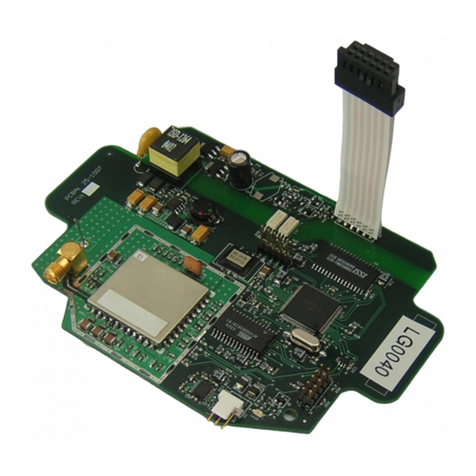
- WZU-MI mit Impulseingängen (Typ „MI“), siehe
Abbildung Abb.: WZU-MI
Das Modul „MI“ besitzt zwei integrierte Impulszähler und bildet aus den Impulsen angeschlossener
Impulsgeber mit Hilfe der parametrierten Impulswertigkeiten kumulierte Volumina. Diese Volumenwerte
werden in den UH50 übertragen, dort gespeichert und auf Wunsch angezeigt oder ausgegeben. Ist keine
M-Bus-Spannung angeschlossen, versorgt eine Batterie den Modulprozessor und die Impulseingänge.
Ab der Modulfirmware 4.11 und der Zählerfirmware 5.17 sind die Module auch für NTA-konforme
Kommunikation geeignet.
Als Vorgänger für die hier beschriebenen Module existieren die M-Bus-Module der 2. Generation. Bei der
Beschreibung der Funktionen wird entsprechend unterschieden.
2 Einbau und Montage
Der Zähler UH50 besitzt zwei Modulsteckplätze zur Aufnahme von Zusatzmodulen. Diese sind auf dem
Zifferblatt mit „Modul 1“ und „Modul 2“bezeichnet (nach Abnehmen des Deckels sichtbar).
Das Modul „MB G4“darf auf beiden Steckplätzen bestückt werden, das Modul „MI“(mit Impulseingängen)
darf ausschließlich auf Modulsteckplatz 1 bestückt werden.
M-Bus Imp1 Imp2
+ - + -
90 63 590 c09.08.2010

M-Bus-Modul WZU-Mx Montage- und Bedienungsanleitung
M-Bus-Modul WZU-MB / MI Änderungen vorbehalten Seite 2 / 10
Das Modul „MI“ wird mit einer eingebauten Batterie ausgeliefert. Kurzschlüsse auf der Baugruppe sind zu
vermeiden. Die einschlägigen Vorschriften im Umgang mit elektrostatisch gefährdeten Baugruppen sind zu
beachten.
Für die Verbindung zur M-Bus-Zentrale (bzw. M-Bus-Repeater) und für die Impulseingänge sind jeweils 2
flexible Leitungen mit einem Aderquerschnitt von 0,25 mm2bis 0,75 mm2vorzusehen, die in einer
mehradrigen Steuerleitung zusammengefasst werden sollen.
Der Außendurchmesser der Leitung darf zwischen 4 mm und 6 mm betragen. Alle Leitungen müssen durch
die vorhandenen Durchführungstüllen in den Zähler geführt werden. Es ist u.U. sinnvoll, die M-Bus-
Leitungen und die Leitungen für die Impulseingänge vor dem Zähler in einer Verteilerdose auf eine
mehradrige Steuerleitung umzusetzen.
Falls ein geschirmtes Kabel für die M-Bus-Spannung bzw. Impulseingänge verwendet wird:
Der Schirm darf nicht auf der Zählerseite angeschlossen werden (nur einseitig anschließen).
2.1 Anzeige in der LCD des Zählers
Die folgenden Anzeigen sind beispielhaft und können von der tatsächlichen Anzeigeliste des Zählers
abweichen.
Nutzerschleife („LOOP 0“)
aktueller Wert Impulszähler 1;
im 2-Sek.-Wechsel
aktueller Wert Impulszähler 2;
im 2-Sek.-Wechsel
Serviceschleife 1 („LOOP 1“)
Vorjahreswert Impulszähler 1;
im 2-Sek.-Wechsel
Vorjahreswert Impulszähler 2;
im 2-Sek.-Wechsel
Serviceschleife 3 („LOOP 3“)
Vormonatswert Impulszähler 1;
im 2-Sek.-Wechsel
Vormonatswert Impulszähler 2;
im 2-Sek.-Wechsel
Serviceschleife 4 („LOOP 4“)
Typ „MI“ auf Steckplatz „Modul 1“;
im 2-Sek.-Wechsel
Typ „MB“ auf Steckplatz „Modul 1“;
im 2-Sek.-Wechsel
Typ „MB“ auf Steckplatz „Modul 2“;
im 2-Sek.-Wechsel;
Zählernummer für Impulszähler 1;
im 2-Sek.-Wechsel;
Zählerwertigkeit für Impulszähler 1;
im 2-Sek.-Wechsel;
Zählernummer für Impulszähler 2;
im 2-Sek.-Wechsel;
Zählerwertigkeit für Impulszähler 2;
im 2-Sek.-Wechsel;
3 M-Bus-Teil
3.1 Technische Daten M-Bus-Teil
Norm EN 1434-3; EN 13757 Teil 2, Teil 3
Protokoll EN 60870-5
galvanische Trennung vom Zähler: ja
von den Impulseingängen: nein
Anschluss Abisolierlänge 5 mm
Anschlussvermögen
- starr oder flexibel, 0,25...0,75 mm²
- flexibel mit Aderendhülse, 0,25...0,75 mm²
Polarität beliebig
Spannung 50 V DC maximal
Stromaufnahme 1 M-Bus-Last (1,5 mA)
Adressierung primär oder sekundär
Baudrate 300, 1200, 2400, 4800 oder 9600 Baud
Schnittstellenbeschreibung siehe TKB3448

M-Bus-Modul WZU-Mx Montage- und Bedienungsanleitung
M-Bus-Modul WZU-MB / MI Änderungen vorbehalten Seite 3 / 10
3.2 Parametrierung der M-Bus-Funktion
3.2.1 Parametrierbereitschaft herstellen
Für die Parametrierung muss der Zähler mit der Servicetaste in den Parametriermodus gebracht werden.
Hierzu Gehäusedeckel abnehmen, Servicetaste ca. 3 Sekunden lang betätigen und Gehäusedeckel wieder
aufsetzen. Optokopf aufsetzen und die Servicesoftware starten.
3.2.2 M-Bus-Modul parametrieren
Im Menü „Parametrierung“/ Untermenü „M-Bus Modul G4“werden die Parameter für das jeweilige
gesteckte Modul festgelegt.
Für die Module vom Typ „MI“ und „MB G4“ gilt: Die Parameter werden wirksam, sobald der Zähler in den
Normalbetrieb zurückkehrt, auch wenn die Busspannung am Modul bereits anliegt.
Das obige Bild zeigt die Möglichkeiten der Parametrierung der M-Bus-Module.
Primäradresse setzen:
Die Primäradressen jeweils für „Modul 1“ und „Modul 2“ setzen
Sekundäradresse setzen (=Eigentumsnummer des UH50):
Die Sekundäradresse gemeinsam für „Modul 1“ und „Modul 2“ setzen
Normalauslesemodus oder Schnellauslesemodus für „Modul 1“bzw. „Modul 2“auswählen:
Darstellungsart der ausgegebenen Werte auswählen:
- nach EN 13757 Teil 3 („modern“)
- wie bei der 2. Generation (abwärtskompatibel = Auslieferungszustand)
- Ausgabe mit festem Rahmen nach EN1434-3 (1997)
Kennung für Medium:
legt fest, welches Medium im M-Bus-Telegramm angegeben wird, z.B. 04 = Wärme
Benutzersicherung setzen:
die Benutzersicherung sperrt die Ausführung bestimmter M-Bus-Befehle
Benutzersicherung löschen:
gibt die Ausführung bestimmter M-Bus-Befehle wieder frei

M-Bus-Modul WZU-Mx Montage- und Bedienungsanleitung
M-Bus-Modul WZU-MB / MI Änderungen vorbehalten Seite 4 / 10
dauerhaft anwenderspezifisch angepasste Werteausgabe im Normalauslesemodus:
Beschreibung siehe „M-Bus-Werteausgabe permanent verändern“
dauerhaft anwenderspezifisch angepasste Werteausgabe im Schnellauslesemodus:
Beschreibung siehe „M-Bus-Werteausgabe permanent verändern“
Eine Änderung der M-Bus-Primäradressen und der M-Bus-Sekundäradresse im Menü
„M-Bus Modul G4“ der Servicesoftware ist auch für M-Bus-Module der 2. Generation wirksam.
3.2.3 M-Bus-Werteausgabe temporär verändern
Wie schon bei den M-Bus-Modulen der 2. Generation, kann mit dem Auswahlbefehl
SND_UD mit CI=51 und aneinandergeketteten Auswahlparametern (DIFs und VIFs)
eine Auswahl der auf dem M-Bus ausgegebenen Daten getroffen werden.
Mit dem Abschalten der Busspannung geht diese im Modul programmierte Auswahl wieder verloren; nach
erneutem Einschalten der Busspannung werden wieder die dauerhaft ausgewählten Werte ausgegeben.
Bei den Modulen der 2. Generation konnte mit diesem Verfahren nur eine Untermenge aus den Standard-
Werten für die Anzeige ausgewählt werden.
Neu ist die Möglichkeit bei den M-Bus-Modulen von Typ „MB G4“ und „MI“, aus einer größeren Auswahl
von derzeit 63 möglichen Werten (siehe M-Bus-Schnittstellenbeschreibung TKB3448) analog zu den oben
beschriebenen Auswahlbefehlen eine individuelle Werteausgabe zusammenzustellen. Dabei kann nicht nur
eine Untermenge der im Normaltelegramm ausgegebenen Werte gewählt werden, sondern es können
noch andere Werte der Auswahl-Liste übertragen werden.
Beispiel:
Das Modul ist im Normalauslesungsmodus mit „G4-kompatibler Anzeige“.
In der Werteausgabe sollen die aktuelle Wärmemenge (Bestandteil der Normalauslesung) und das
Leistungsmaximum des Vormonats mit dem zugehörigen Zeitstempel des Leistungsmaximums des
Vormonats (kein Bestandteil der Normalauslesung) stehen.
Sendedaten:
68h 0Ch 0Ch 68h 53h 21h 51h 98h 11h ADh 6Fh 08h 06h 98h 11h 2Dh 6Eh 16h.
Hierbei bedeuten:
68 0C 0C 68 Start Rahmen mit variabler Länge
53 C-Feld (SND_UD)
21 Primäradresse 33 (Dezimal)
51 CI-Feld
98 11 AD 6F Zeitstempel Maximum Wärmeleistung Vormonat
08 06 Auswahl aktuelle Wärmemenge
98 11 2D Maximum Wärmeleistung Vormonat
6E Checksumme
16 Ende Rahmen mit variabler Länge
Quittung für obiges Telegramm:
Empfangen: E5h (OK)
Nachfolgende Daten auslesen (REQ_UD2):
Gesendet: 10h 7Bh 21h 9Ch 16h
Empfangen: 68h 29h 29h 68h 08h 21h 72h 78h 56h 34h 12h A7h 32h ...
Beispiel der Decodierung:
Adr.:33 Nr.:12345678 Herst.:LUG Gen.:4 Med.:Wärme Cnt.:204 Stat.:0
Energie: 14524 kWh
Leistung : 0.0 kW Maximum Tarif: 1 Speichernr.: 2
Zeitstempel Leistung: (leerer Wert) Maximum Tarif: 1 Speichernr.: 2
Herstellerdaten: A010001709
Wurde im Zähler ein entsprechender Vormonatsstichtag noch nicht überschritten und infolgedessen ein
angefragter Vormonatswert noch nicht abgespeichert, werden die (leeren) Vormonatswerte mit dem Wert
„0“ bzw. „0.0“ ausgegeben und die Zeitstempel erhalten die Kennzeichnung „leerer Wert“(00h 00h 00h
00h) .
3.2.4 M-Bus-Werteausgabe permanent verändern (anwenderspezifisch anpassen)
Die Module vom Typ „MI“ und „MB G4“ ermöglichen es, die Ausgabe der Messwerte aus dem M-Bus-
Modul auch permanent an die individuellen Erfordernisse des Anwenders anzupassen. Die dazu
notwendigen Steuerparameter werden im Zähler gespeichert und vom M-Bus-Modul beim Anlegen der
Busspannung aus dem Zähler ausgelesen.
Mit der Servicesoftware können mittels „Drag&Drop“ die Ausgabelisten für den Normalauslesemodus und
den Schnellauslesemodus zusammengestellt werden.

M-Bus-Modul WZU-Mx Montage- und Bedienungsanleitung
M-Bus-Modul WZU-MB / MI Änderungen vorbehalten Seite 5 / 10
Dies erfolgt im Menü Parametrierung / Untermenü M-Bus Modul G4 über die Funktion „Daten
selektieren“.
Die nachfolgenden Beschränkungen sind zu beachten.
Normalauslesemodus: maximal 228 Werte-Ausgabebytes im M-Bus-Rahmen
Schnellauslesemodus: maximal 8 Messwerte pro Telegramm
keine Ausgabe von Vormonatswerten und Vorjahreswerten
im M-Bus-Telegramm
In den Spalten „Normalauslesemodus“ und „Schnellauslesemodus“ wird mit „Maximale Telegrammlänge
[Ist-Länge/ max. Länge]“ der aktuelle Stand der Telegrammlänge angezeigt.
Hinweis: Die Reihenfolge der ausgewählten Werte hat keinen Einfluss auf die Reihenfolge der
Werteausgabe im M-Bus-Telegramm.
Vormonatswerte und Vorjahreswerte werden im Schnellauslesemodus nicht ausgegeben.
Mit der Schaltfläche „Set Default values“ werden für „Normalauslesemodus“ und „Schnellauslesemodus“
die Werkseinstellungen der Ausgabelisten wiederhergestellt. Die Ausgabelisten entsprechen dann der
2. Generation und sind somit abwärtskompatibel.
4 NTA-konforme Datenausgabe
NTA 8130 (Netherlands Technical Agreement) ist eine in den Niederlanden entstandene Vorschrift mit dem
Ziel, Verbrauchsgeräte (Elektro- Gas-, Wärme- und Wasserzähler) in der Kommunikation interoperabel zu
verbinden und so die modernen Anforderungen von Smart Metering zu erleichtern.
Die genauen Anforderungen und Prozeduren sind in den Vorschriften „Dutch Smart Metering
Requirements“ - für das Zähler-M-Bus-Modul gilt der „P2 Companion Standard“ - (DSMR P2) beschrieben.
Ab der Firmware-Version 4.11 des M-Bus-Moduls WZU-Mx ist die „NTA-konforme Datenausgabe“ neben
„Normalauslesemodus“ und „Schnellauslesemodus“ eine dritte Betriebsart.
Im Betriebsmodus „NTA-konforme Datenausgabe“ ist die Ausgabeliste der Daten auf die M-Bus-
Schnittstelle fest vorgegeben und variiert nur mit dem „device type“ (=M-Bus-Kennung für den Medientyp).
Der Zähler muss für die Nutzung der NTA-konformen Datenausgabe mindestens den Firmwarestand
5.17 haben.
Die Aktivierung der NTA-konformen Datenausgabe wird mit der Servicesoftware am Zähler vorgenommen.
Die Einstellung erfolgt im Menü „Parametrierung“ / Untermenü „
NTA“
. Dieser Menüpunkt wird ab
Zählerfirmware 5.17 angeboten, wenn der Zähler in Parametrierbereitschaft ist. Dabei ist es nicht
erforderlich, dass das entsprechende Modul bereits im Zähler gesteckt ist.

M-Bus-Modul WZU-Mx Montage- und Bedienungsanleitung
M-Bus-Modul WZU-MB / MI Änderungen vorbehalten Seite 6 / 10
4.1 Equipment identifier
In der NTA-konformen M-Bus-Ausgabe benötigen Geräte einen 17-stelligen equipment identifier (17 Stellen
ASCII-Text). Ab Firmware Version 5.17 erhalten die Zähler werksseitig den sogenannten KEMA-Code als
equipment identifier. Der equipment identifier erlaubt im NTA-konformen M-Bus-Telegramm eine exakte
Identifikation des Zählers.
4.1.1 Equipment identifier kontrollieren
Dazu muss zuerst die Parametrierbereitschaft hergestellt werden (siehe Abschn. 3.2.1).
Im Menü „Parametrierung“ / Untermenü „NTA“ werden für die Funktionalitäten nach NTA folgende
Untermenü-Punkte angeboten:
Equipment identifier eingeben
Equipment identifier bereitstellen (auslesen)
Debinding NTA-Modul (vollständig; wired und wireless)
Den Untermenüpunkt „Equipment identifier bereitstellen (auslesen)“ anwählen und der im Zähler
gespeicherte Wert wird auf dem Textfeld der Servicesoftware ausgegeben.
4.1.2 Equipment identifier ändern /neu parametrieren
Soll der eingestellte equipment identifier verändert werden, ist wie folgt zu verfahren:
Zuerst muss die Parametrierbereitschaft hergestellt werden (siehe Abschn. 3.2.1).
Im Menü „Parametrierung“ / Untermenü „NTA“ ist der Untermenüpunkt „Equipment identifier eingeben“
anzuwählen.
Equipment identifier eingeben
Equipment identifier bereitstellen (auslesen)
Debinding NTA-Modul (vollständig; wired und wireless)
Es öffnet sich ein Fenster:
In dieses Fenster kann ein neuer equipment identifier nach folgenden Regeln eingegeben werden:
Die zulässigen Zeichen entsprechen den druckbaren Zeichen nach ISO/IEC 8859-1.
Es dürfen maximal 30 ASCII-Zeichen eingeben werden; längere Eingaben werden bei der
Übertragung in den Zähler gekappt.
Durch Betätigen des Buttons OK wird die Auswahl in den Zähler übertragen.
Hinweis:Werden keine Zeichen in das Eingabefeld eingegeben (leer lassen), wird der aktuelle equipment
identifier mit Betätigung des Buttons OK gelöscht.
4.2 NTA-Funktionalität aktivieren
Die Steuerung der Modulbetriebsart wird mit der Servicesoftware am Zähler (NTA-Funktionalität ab Zähler-
Firmware-Version 5.17 möglich) durchgeführt.
4.2.1 NTA-Debinding-Prozedur
Mit der Debinding-Prozedur wird das Modul in einen NTA-Betriebsmodus geschaltet, in dem es vom NTA-
konformen Master (z.B. Elektrozähler) als neuer Partner erkannt und gebunden werden kann (Binding).
Beim Debinding werden im UH50 ggf. alte NTA-Schlüssel gelöscht, die Primäradresse auf 00h eingestellt
und das Modul wird in einen NTA-Betriebsmodus geschaltet, in dem es vom NTA-konformen Master (z.B.
Elektrozähler) als neuer Partner erkannt und gebunden werden kann (Binding).

M-Bus-Modul WZU-Mx Montage- und Bedienungsanleitung
M-Bus-Modul WZU-MB / MI Änderungen vorbehalten Seite 7 / 10
Dazu muss zuerst die Parametrierbereitschaft hergestellt werden (siehe Abschn. 3.2.1).
Im Menü „Parametrierung“ / Untermenü „NTA“ werden für die Funktionalitäten nach NTA folgende
Untermenü-Punkte angeboten:
Equipment identifier eingeben
Equipment identifier bereitstellen (auslesen)
Debinding NTA-Modul (vollständig; wired und wireless)
Jetzt den Untermenüpunkt „Debinding NTA-Modul (vollständig; wired und wireless)“anwählen.
Die Servicesoftware stellt die Anfrage:
Hier bitte eingeben, ob das M-Bus-Modul auf dem Steckplatz 1 oder 2 des Zählers steckt oder stecken soll
und mit OK bestätigen.
Das entsprechende M-Bus-Modul ist jetzt im NTA-Betriebsmodus.
In der LCD des Zählers ist (bei gestecktem WZU-MB G4- oder WZU-MI-Modul) in LOOP 4 das erfolgte
Debinding sichtbar:
LCD des Zählers, Serviceschleife 4 („LOOP 4“)
für Modulsteckplatz 1
Typ „MB“ auf Steckplatz „Modul 1“;
im 2-Sek.-Wechsel
wechselt zu
Typ „MB“ auf Steckplatz „Modul 1“;
im 2-Sek.-Wechsel
für Modulsteckplatz 2
Typ „MB“ auf Steckplatz „Modul 2“;
im 2-Sek.-Wechsel;
wechselt zu
Typ „MB“ auf Steckplatz „Modul 2“;
im 2-Sek.-Wechsel;
Im Sinne von DSMR P2 dient vor Ort ein Elektrizitätszähler als M-Bus-Master. Dieser Master übernimmt
das Binding Zählers mit dem NTA-fähigen M-Bus-Modul. Für die genauen Anmeldeprozeduren an den
Master siehe die Bedienungsanleitung des Elektrizitätszählers.
Wenn das Modul erfolgreich an den Elektrozähler gebunden wurde (Binding), wechselt die Anzeige in
LOOP 4 von
in und die Bindingprozedur nach DSMR P2 ist erfolgt.
Nach dem Binding des Moduls bestimmt der Master die weitere M-Bus-Kommunikation.
Hinweis: Im NTA-Betrieb wird die Zeitsynchronisation des Zählers vom Master übernommen. Deshalb
wird bei der NTA-Debinding-Prozedur die Sommer-/Winterzeittabelle im Zähler gelöscht. Die
Sommer-/Winterzeittabelle kann erst wieder parametriert werden, wenn sowohl für den
Modulsteckplatz 1 als auch 2 keine NTA-Funktionalität (wired oder wireless) parametriert ist.
4.3 NTA-Funktionalität beenden
Wenn die NTA-Funktionalität des M-Bus-Moduls beendet werden soll, ist zuerst ein Debinding gemäß
Abschnitt 4.2.1 durchzuführen.

M-Bus-Modul WZU-Mx Montage- und Bedienungsanleitung
M-Bus-Modul WZU-MB / MI Änderungen vorbehalten Seite 8 / 10
Dies ist notwendig um Parametrierungen, die während des NTA-Betriebs im Zähler durchgeführt wurden,
wieder zurückzusetzen.
Danach im Menü „Parametrierung“ das Untermenü „M-Bus Modul G4“öffnen:
Wenn der NTA-Modus für das M-Bus-Modul parametriert ist, wird dies im Unterpunkt „M-Bus-
Auslesemodus (im Beispiel für Modulsteckplatz 1) durch das zusätzliche Textfeld „NTA-Modus“ angezeigt.
Wenn „Normalauslesemodus“ oder „Schnellauslesemodus“ gewählt wurde und die Auswahl mit OK
bestätigt wird, ist die NTA-Funktionalität für das entsprechende Modul beendet.
Das M-Bus-Modul WZU-Mx funktioniert entsprechend der im M-Bus Auslesemodus gewählten Betriebsart
„Normalauslesemodus“ oder „Schnellauslesemodus“.
Hinweis:Wenn weder für die Modulsteckplatz 1 noch für die Modulsteckplatz 2 ein NTA-Modus
parametriert ist, kann jetzt bei Bedarf wieder die Sommer-/Winterzeittabelle im Zähler
parametriert werden. Die Sommer-/Winterzeit-Umschaltung ist dann wieder aktiviert.
5 Impulsteil des Moduls „MI“
Das Modul „MI“ ist mit zwei vom Zähler galvanisch getrennten Impulseingängen ausgestattet.
Hinweis: Die aus den Impulseingängen im Zähler gebildeten Volumenwerte sind nicht eichfähig.
Das Modul „MI“ ist zusätzlich zur möglichen Spannungsversorgung über den M-Bus-Anschluss mit einer
Batterie ausgerüstet. Diese übernimmt die Versorgung für den Modulprozessor und die Impulseingänge,
wenn keine M-Bus-Spannung anliegt.
Als Impulsgeber für die Impulseingänge sind entweder potentialfreie Kontakte (z-B. Relais-Kontakte oder
Reed-Kontakte) oder elektronische Geber als „open collector“ möglich.
Wenn als Geber der Impulseingänge eine „open collector“-Schaltung verwendet wird, dürfen die Leitungen
in keinem Fall mit den M-Bus-Eingängen des MI-Moduls galvanisch verbunden sein.

M-Bus-Modul WZU-Mx Montage- und Bedienungsanleitung
M-Bus-Modul WZU-MB / MI Änderungen vorbehalten Seite 9 / 10
5.1 Technische Daten Impulsteil
Anzahl der Impulseingänge 2 Impulseingänge je Modul „MI“
Anzahl MI-Module pro UH50 ein Modul „MI“; nur auf Steckplatz Modul 1 zulässig
Lebensdauer der Modulbatterie 5 Jahre Betrieb + 1 Jahr Lagerdauer;
wenn am Modul während min. 90% der Betriebszeit die M-Bus-
Spannung anliegt, erhöht sich die Batterielebensdauer auf
10 Jahre Betrieb
Norm für Impulseingänge Klasse IB nach EN 1434-2
Frequenz max. 10 Hz
Impulsdauer (Low) ≥ 50 ms
Impulspause (High) ≥ 50 ms
Impulswertigkeit 0,01 Liter / Impuls bis 10.000,00 Liter / Impuls,
in Schritten von 0,01 Liter / Impuls
Anzeige und Ausgabe im UH50 in m3, 7-stellig;
je nach Parametrierung ohne oder mit 1 Nachkommastelle
Polarität ja, muss beachtet werden, wenn Geber vom Typ „open collector“
ist
galvanische Trennung vom Zähler: ja
von den M-Bus-Eingängen: nein
Ausgangsspannung ca. 3,3 V
Innenwiderstand ca. 1 MΩ
Quellenstrom ca. 3 µA
Impulseingang geschlossen (Low)
Schaltschwelle Low < 0,2 V
Widerstand < 50 kΩ
Impulseingang offen (High)
Schaltschwelle High nicht durchgesteuerter Kollektor
Widerstand ≥ 6 MΩ
Anschluss Abisolierlänge 5 mm
Anschlussvermögen
- starr oder flexibel, 0,25...0,75 mm²
- flexibel mit Aderendhülse, 0,25...0,75 mm²
zulässige Leitungslänge max. 10 m
Die Leitungen sollten so kurz wie möglich sein und in keinem Fall
eine Länge von 10 m überschreiten.
5.2 Parametrierung der Impulsfunktionen
Das Modul „MI“ wird im „Lagermodus“ausgeliefert, das heißt:
- das Modul wird von einer Batterie mit Spannung versorgt,
- die Parameter „Gerätenummer“, „Zählerstand“, „Impulswertigkeit“und „Nachkommastelle“ sind Null,
- die Impulseingänge sind inaktiv.
Solange das Modul keine Parametrierdaten erhält, bleiben die Impulseingänge inaktiv.
5.2.1 Impulseingänge aktivieren
Zähler in den Parametriermodus bringen (siehe „3.2.1 Parametrierbereitschaft herstellen“).
Im Menü Parametrierung / Untermenü Impulseingang werden die Werte für die Parameter „Geräte-
nummer“, „Zählerstand“, „Impulswertigkeit“, „Nachkommastelle“ sowie die Mediumskennung im M-Bus-
Telegramm festgelegt. Die Parametrierung erfolgt getrennt für Impulseingang 1 und Impulseingang 2.
Mit der Schaltfläche „OK“ werden die eingegebenen Parameter übertragen.

M-Bus-Modul WZU-Mx Montage- und Bedienungsanleitung
M-Bus-Modul WZU-MB / MI Änderungen vorbehalten Seite 10 / 10
Wenn die Impulseingänge parametriert sind, arbeitet das Modul „MI“ wie folgt:
Die Impulse an den Impulseingängen werden gezählt.
Alle 5 Minuten wird aus den gezählten Impulsen und der Impulswertigkeit ein Zählwerksfortschritt in
1 m3oder 0,1 m3(je nach Nachkommastelle) berechnet und der Impulszählerstand aktualisiert; der
Impulszählerstand wird an den Zähler übertragen und dort gespeichert.
5.2.2 Impulseingänge deaktivieren („Lagermodus“)
Wenn ein oder beide Impulseingänge deaktiviert werden sollen (Lagermodus; nur bei deaktivierten
Impulseingängen), wird für den jeweiligen Impulseingang im oben beschriebenen Menü der Parameter für
die Impulswertigkeit auf Null gesetzt. Mit der Schaltfläche „OK“ werden die Parameter übertragen.
Für einen deaktivierten Impulseingang werden keine Impulse mehr gezählt.
5.3 Modulwechsel
Beim Austausch eines Moduls vom Typ „MI“ muss das neue Modul initialisiert werden.
Nach dem Stecken und Anschließen des neuen Moduls den Zähler in den Parametriermodus bringen
(siehe „3.2.1 Parametrierbereitschaft herstellen“).
Im Menü Parametrierung / Untermenü Impulseingang werden die aktuell im UH50 gespeicherten Para-
meter der Impulseingänge ausgelesen und angezeigt.
Die angezeigten Werte werden –wenn nötig –korrigiert oder der jeweilige Impulseingang wird ohne
Parameteränderung mit der Schaltfläche „Impulseingang 1 initialisieren“ bzw. „Impulseingang 2
initialisieren“ parametriert.
Nach Rückkehr des Zählers in den Normalmodus arbeitet das Modul wie vorgegeben.
6 Bestellangaben
für einzelnen Modul: WZU-MB G4 oder WZU-MI
für Wärmezähler mit Modul: UH50-xxxx-xxxx-xxx-xYZx-xxx
YZ = N_ für Type „MI“ als Modul 1
YZ = NB für Type „MI“ als Modul 1 und Type „MB G4“als Modul 2
YZ = B_ für Type „MB G4“ als Modul 1
YZ = _B für Type „MB G4“ als Modul 2
YZ = BB für Type „MB G4“als Modul 1 und Type „MB G4“ als Modul 2
Aktuelle Informationen zu unseren Wärmezählern finden Sie auch im INTERNET unter:
www.landisgyr.com
Landis+Gyr GmbH
Humboldtstr. 64
D-90459 Nürnberg
Deutschland

M-Bus-Module WZU-Mx Installation and Operating Guide
M-Bus-Module WZU-MB / MI Subject to changes Page 1 / 10
Safety Information
- Comply with ESD protection measures
- The M-bus module with pulse inputs is supplied with a built-in battery –avoid short-circuits on the
PCB
- Disconnect the M-bus voltage during connection work
- Route connecting cables only through the bush sleeves of the meter
- Do not cut the bush sleeves shorter than necessary because this may lower the degree of protection
1 Description of function
The M-bus module is an add-on module for the type
UH50 meter (firmware 5.15 and higher). The module
enables the meter to communicate with an M-bus
center in order to transmit measured values.
This description applies to M-bus modules of the “4th
generation”: These modules are available in two
types:
- WZU-MB G4 (type “MB G4”)no picture
- WZU-MI with pulse inputs (type “MI”), see picture picture: WZU-MI
The module has two integrated pulse counters and calculates cumulated volumes from the pulses coming
from connected pulse transmitters according the parametrized significance. These volume values are
transmitted to the UH50 where they are stored and can be displayed or output as required. If no M-bus
voltage is connected, a battery powers the module processor and the pulse inputs.
For the module firmware 4.11 and higher and the meter firmware 5.17 and higher, the modules are
also suitable for NTA-compliant communication.
There is also the predecessor model of the 2nd generation. The description of the functions makes a
distinction where this is appropriate.
2 Installation and assembly
The UH50 meter has two module slots for fitting add-on modules. These are named “Modul 1” and
“Modul 2” on the dial plate (visible after removing the cover).
Module “MB G4” may fitted on both of the slots. Module „MI“ (with pulse inputs) must only be fitted at
slot module 1.
Module “MI” is supplied with a built-in battery. Short-circuits on the PCB must be avoided. The relevant
rules for handling electrostatically sensitive devices must be observed.
M-bus Pulse1 Pulse2
+ - + -
90 63 590 c 2010/08/09

M-Bus-Module WZU-Mx Installation and Operating Guide
M-Bus-Module WZU-MB / MI Subject to changes Page 2 / 10
For connection with the M-bus center (or M-bus repeater) and for the pulse inputs, 2 flexible cables with a
conductor cross-section of 0.25 mm2to 0.75 mm2are provided, which are to be combined to a multi-core
line.
The outer diameter of the cable must be between 4 mm and 6 mm. All cables have to be routed through
the existing bush sleeves in the meter. It may be convenient to combine the M-bus cables and the cables
for the pulse inputs in a single multi-conductor cable outside the UH50 in a splitting box.
If a shielded cable is used for the M-bus voltage or pulse inputs: The shield must not be
connected at the meter end (only connect at one end).
2.1 Display on the LCD of the meter
The following displays are examples and may differ from the actual display list of the meter.
User loop (“LOOP 0”)
Current value pulse meter 1;
in 2-sec. cycles
Current value pulse meter 2;
in 2-sec. cycles
Service loop 1 (“LOOP 1”)
Previous year pulse meter 1;
in 2-sec. cycles
Previous year pulse meter 2;
in 2-sec. cycles
Service loop 3 (“LOOP 3”)
Previous month pulse meter 1;
in 2-sec. cycles
Previous month pulse meter 2;
in 2-sec. cycles
Service loop 4 (“LOOP 4”)
Type “MI” in slot “Module 1”;
in 2-sec. cycles
Type “MI” in slot “Module 1”;
in 2-sec. cycles
Type “MI” in slot “Module 2”;
in 2-sec. cycles;
Meter scaling for pulse meter 1;
in 2-sec. cycles;
Meter scaling for pulse meter 1;
in 2-sec. cycles;
Meter scaling for pulse meter 2;
in 2-sec. cycles;
Meter scaling for pulse meter 2;
in 2-sec. cycles;
3 M-bus part
3.1 Technical data of the M-bus part
Standard EN 1434-3; EN 13757 Part 2, Part 3
Protocol EN 60870-5
Electrical isolation from the meter: yes
from the pulse inputs: no
Connection Insulation stripping length 5 mm
Connection capacity
- rigid or flexible, 0.25...0.75 mm²
- flexible with ferrules, 0.25...0.75 mm²
Polarity any
Voltage 50 V DC maximal
Current consumption 1 M-bus load (1.5 mA)
Addressing Primary or secondary
Baudrate 300, 1200, 2400, 4800 or 9600 baud
Interface description see TKB3448
3.2 Parameter setting of the M-bus function
3.2.1 Preparing parameterization
For parameterization, the meter must be put into parameter setting mode with the service button. First
remove the housing cover, then press the service button for about 3 seconds, then replace the housing
cover. Apply the opto-head and start the service software.

M-Bus-Module WZU-Mx Installation and Operating Guide
M-Bus-Module WZU-MB / MI Subject to changes Page 3 / 10
3.2.2 M-bus module parameterization
In the menu “Parameterization” / submenu “M-bus module G4”, the parameters are defined for the
particular module that is plugged in.
For the module types “MB G4” and “MI” the following applies: The parameters become effective as soon as
the meter returns to normal mode, even when the bus voltage is already applied to the module.
The above figure shows the options for setting the parameters of M-bus modules.
Setting the primary address:
Set the primary addresses for „Module 1“ and „Module 2“ respectively
Set the secondary address (= property number of UH50):
Set the shared secondary address for “Module 1” and “Module 2”
Select normal read-out mode or fast read-out mode for “Module 1” and “Module 2”:
Select the type of representation for the output values:
- according to EN 13757 Part 3 (“modern”)
- as for the 2nd generation (downward compatible = default setting at delivery)
- output with fixed frame according to EN1434-3 (1997)
Identification for medium type:
Defines which medium is referred to in the M-bus telegram, e.g. 04 = heat
Set the user lock:
The user lock disables the execution of certain M-bus commands
Clear user lock:
Enables execution of certain M-bus commands again
Permanently customized value output in normal read-out mode:
For a description, see “Changing M-bus value output permanently“
Permanently customized value output in fast read-out mode:
For a description, see “Changing M-bus value output permanently“
A change to the M-bus primary addresses and the M-bus secondary address in the
“M-bus module G4” menu is also effective for M-bus modules of the 2nd generation.

M-Bus-Module WZU-Mx Installation and Operating Guide
M-Bus-Module WZU-MB / MI Subject to changes Page 4 / 10
3.2.3 Changing M-bus value output temporarily
As was already the case with M-bus modules of the 2nd generation, with the selection command
SND_UD with CI=51 and chained selection parameters (DIFs and VIFs)
it is possible to select the data to be output on the M-bus.
When the bus voltage is disconnected, this selection programmed in the module will be lost again; after bus
voltage recovery, the permanently selected values will be output again.
In the case of the modules of the 2nd generation, it was possible to select only a subset of the standard
values for the display using this method.
One new feature is the option of putting together an individual value output from a larger selection of 63
values on M-bus modules “MB G4” and “MI” in an analogous way to the selection commands described
above (see M-bus interface description TKB3448). It is possible to select not only a subset of the values
output in the normal telegram, but other values of the selection list can also be transmitted.
Example:
The module is in normal read-out mode with a “G4-compatible display”.
The value output is to contain the current heat quantity (part of the normal read-out) and the power
maximum of the previous month with the appropriate timestamp of the power maximum of the previous
month (not part of the normal read-out).
Transmitted data:
68h 0Ch 0Ch 68h 53h 21h 51h 98h 11h ADh 6Fh 08h 06h 98h 11h 2Dh 6Eh 16h.
Where: 68 0C 0C 68 Beginning of frame with variable length
53 C-field (SND_UD)
21 Primary address 33 (decimal)
51 CI-field
98 11 AD 6F Time stamp maximum heat power previous month
08 06 Selection of current heat quantity
98 11 2D Maximum heat power previous month
6E Checksum
16 End of frame with variable length
Acknowledgment of the above telegram:
Received: E5h (OK)
Read out the following data (REQ_UD2):
Transmitted: 10h 7Bh 21h 9Ch 16h
Received: 68h 29h 29h 68h 08h 21h 72h 78h 56h 34h 12h A7h 32h ...
Example of the decoding:
Addr.:33 No.:12345678 Manu.:LUG Gen.:4 Med.:Heat Cnt.:204 Stat.:0
Energy: 14524 kWh
Power: 0.0 kW Maximum Tariff: 1 Storage No.: 2
Timestamp power: (empty value) Maximum Tariff: 1 Storage No.: 2
Manufacturer data: A010001709
If a corresponding previous month’s set day has not yet been passed in the meter and a requested
previous month’s value has therefore not yet been stored, the (empty) previous month’s values are output
with the value “0” or “0.0” and the timestamps contain the note “empty value” (00h 00h 00h 00h).
3.2.4 Changing M-bus value output permanently (customizing)
Type “MB G4” and "MI" modules also allow you to adapt the output of measured values from the M-bus
module to individual user requirements permanently. The necessary control parameters are stored in the
meter and read out from the meter by the M-bus module when the bus voltage is applied.
With the service software, the output lists for normal read-out mode and fast read-out mode can be
compiled using drag&drop.

M-Bus-Module WZU-Mx Installation and Operating Guide
M-Bus-Module WZU-MB / MI Subject to changes Page 5 / 10
This is done in the menu Parameterization / submenu M-bus module G4 using the “Select data”
function.
The following restrictions must be observed.
Normal read-out mode: up to 228 values –output bytes in the M-bus frame
Fast read-out mode: up to 8 measured values per telegram
no output of values from the previous month or the previous year
in the M-bus telegram
In the “normal read-out mode” and “fast read-out mode” columns, the current status of the telegram length
is shown in “Maximum frame size [actual length/ max. length]”.
Note: The sequence of the selected values does not have any effect on the sequence of the value output in
the M-bus telegram.
The previous month’s values and the previous year's values are not output in fast read-out mode.
With the “Set Default values” button, the factory settings of the output lists are restored for “normal read-
out mode” and “fast read-out mode”. The output lists are then as they were in the 2nd generation and are
therefore downward compatible.
4 NTA-compliant data output
NTA 8130 (Netherlands Technical Agreement) is a regulation of Dutch origin. Its objective to achieve
interoperable communication between consumption devices (electricity, gas, heat and water meters), and
thus to facilitate the modern requirements of Smart Metering.
The requirements and procedures are described in detail in the „Dutch Smart Metering Requirements“ - the
„P2 Companion Standard“ - (DSMR P2) applies for the meter M-bus module.
In firmware version 4.11 and higher of the M-bus module WZU-Mx, the „NTA-compliant data output“ is a
third operation mode along with the „normal read-out mode“ and the „fast read-out mode“.
In the "NTA-compliant data output“ operating mode, the data output list for the M-bus interface is
predefined, and only varies with the "device type" (=M-Bus identification for the media type).
To use the NTA-compliant data output, the meter must have at least firmware version 5.17.
The NTA-compliant data output is activated using the service software at the meter. The adjustment is
done under the „Parameterization“ / „
NTA“
menu. This menu item will be offered with meter firmware
5.17 and higher, when the meter has been prepared for parameterization. The appropriate module is not
required to be plugged in the meter.

M-Bus-Module WZU-Mx Installation and Operating Guide
M-Bus-Module WZU-MB / MI Subject to changes Page 6 / 10
4.1 Equipment identifier
For NTA-compliant M-bus output, devices require a 17-character equipment identifier (17 characters of
ASCII text). With firmware version 5.17 and higher, the meters receive the "KEMA code" as the equipment
identifier from the factory. In the NTA-compliant M-bus telegram, the equipment identifier enables the exact
identification of the meter in the M-bus telegram.
4.1.1 Controlling the equipment identifier
To do this, the device has to be prepared for parameterization first (see sect. 3.2.1).
The menu „Parameterization“ / submenu „NTA“ offers the following submenu items for the NTA
functions:
Entering the equipment identifier
Provide equipment identifier (read out)
Debinding NTA module (complete; wired and wireless)
Select the submenu item „Provide equipment identifier (read out)“ - the value stored in the meter will be
output in the text field of the service software.
4.1.2 Modifying / reparameterizing the equipment identifier
To modify the set equipment identifier, proceed as follows:
First, the device has to be prepared for parameterization (see sect. 3.2.1).
Select the submenu item „Enter equipment identifier“ in the menu "Parameterization" / submenu
"NTA".
Enter equipment identifier
Provide equipment identifier (read out)
Debinding NTA module (complete; wired and wireless)
A window pops up:
You can enter a new equipment identifier in this window, according to the following rules:
The characters allowed correspond to the printable characters in ISO/IEC 8859-1.
A length of 30 ASCII characters must not be exceeded; longer strings will be cut off when transferred
to the meter.
Clicking the OK button will transfer the selection to the meter.
Note: If no characters are entered into the input field (i.e. if it is left empty), the current equipment
identifier will be deleted as soon as the OK button is pressed.
4.2 Activating the NTA functionality
The control of the module's operating mode is done at the meter (NTA functionality possible in meter
firmware version 5.17 and higher) using the service software.
4.2.1 NTA debinding procedure
With the debinding procedure, the module is switched into an NTA operating mode that allows the NTA-
compliant master (e.g. the electricity meter) to identify and bind it as a new partner device (binding). When
debinding, old NTA keys are deleted in the UH50, if necessary. The primary address is set to 00h and the
module is switched into an NTA operating mode that allows the NTA-compliant master (e.g. the electricity
meter) to identify and bind it as a new partner device (binding).

M-Bus-Module WZU-Mx Installation and Operating Guide
M-Bus-Module WZU-MB / MI Subject to changes Page 7 / 10
To do this, the device has to be prepared for parameterization first (see sect. 3.2.1).
The menu „Parameterization“ / submenu „NTA“ offers the following submenu items for the NTA
functionalities:
Entering the equipment identifier
Provide equipment identifier (read out)
Debinding NTA module (complete; wired and wireless)
Now select the submenu item „Debinding NTA module (complete; wired and wireless)“ .
The service software will ask you to confirm the following dialog box:
Please enter whether the M-bus module is or is to be in slot 1 or 2 of the meter and click OK to confirm.
The respective M-bus module is now in NTA operating mode.
In LOOP 4, the meter LCD will show that the debinding procedure has been completed (if the WZU-MB G4-
or the WZU-MI module is inserted):
Meter LCD, service loop 4 (“LOOP 4”)
for module slot 1
Type "MB" in slot "Module 1";
in 2-sec. cycles
switches to
Type "MB" in slot "Module 1";
in 2-sec. cycles
for module slot 2
Type "MB" in slot "Module 2";
in 2-sec. cycles;
switches to
Type "MB" in slot "Module 2";
in 2-sec. cycles;
According to DSMR P2, an on-site electricity meter will serve as M-bus master. This master will perform the
binding of the meter with the NTA-enabled M-bus module. The exact binding procedure to the master can
be found in the operating guide of the electricity meter.
As soon as the module has been successfully been connected to the electricity meter (binding), the display
in LOOP 4 switches from
to and the binding procedure according to DSMR P2 is complete.
After the binding of the module, the master controls the subsequent M-bus communication.
Note: In NTA operating mode, the master performs the meter's time synchronization. Therefore, the
NTA debinding procedure will delete the summer-/wintertime table in the counter. The summer-
/wintertime table cannot be parameterized again as soon as no NTA functionality (wired oder
wireless) is parameterized for module slot 1 and 2.
4.3 Exiting the NTA functionality
To exit the NTA functionality of the M-Bus module, a debinding procedure according to section 4.2.1 must
be performed first.
This is necessary to reset parameterizations performed in the meter while it was in NTA operating mode.

M-Bus-Module WZU-Mx Installation and Operating Guide
M-Bus-Module WZU-MB / MI Subject to changes Page 8 / 10
Afterwards, open the "M-Bus Module G4" submenu in the "Parameterization“ menu:
If the NTA mode is parameterized for the M-bus module, this is indicated by the additional text field "NTA
mode" in the subitem "M-bus read-out mode" (in the example for module slot 1).
If „Normal read-out mode“ or „Fast read-out mode“ has been selected and the selection has been
confirmed with OK, the NTA functionality for the respective module will be ended.
The M--bus module WZU-Mx works according to the operating mode selected in the M-bus read-out mode
- „normal read-out mode“ or „fast read-out mode“.
Note: If the NTA mode has neither been parameterized for module slot 1 nor for module slot 2, the
meter's summer-/wintertime table can be parameterized again, if necessary. The switch from
summertime to wintertime is activated again.
5 Pulse part of the “MI” module
The “MI” module is equipped with two pulse inputs that are electrically isolated from the meter.
Note: The volume values calculated in the meter from the pulse inputs are not capable of being officially
calibrated.
In addition to a possible voltage supply from the M-bus connection, the “MI” module is equipped with a
battery. This powers the module processor and the pulse input, if no M-bus voltage is applied.
As pulse transmitters for the pulse inputs, either isolated contacts (e.g. relay contacts or Reed contacts) or
electronic transmitters as “open collectors” can be used.
If an “open collector” circuit is used as the transmitter of the pulse inputs, the cable must always be
electrically isolated from the M-bus inputs of the MI module.
5.1 Technical data of the pulse part
Number of pulse inputs 2 pulse inputs per “MI” module

M-Bus-Module WZU-Mx Installation and Operating Guide
M-Bus-Module WZU-MB / MI Subject to changes Page 9 / 10
Number of “MI” modules per UH50 An “MI” module is only permissible in slot Module 1
Life of the module battery 5 years of operation + 1 year storage duration;
if the M-bus voltage is applied for at least 90% of the operating
time, the battery life increased to 10 years
Standard for pulse inputs Class IB per EN 1434-2
Frequency max. 10 Hz
Pulse duration (low) ≥ 50 ms
No-pulse duration (high) ≥ 50 ms
Pulse value 0.01 liters / pulse to 10,000.00 liters / pulse, in steps of 0.01 liters
/ pulse
Display and output in the UH50 in m3, 7-digit;
acc. to parameter setting with or without 1 decimal place
Polarity yes, must be correct, if transmitter is of type “open collector”
Electrical isolation from the meter: yes
from the M-bus inputs: no
Output voltage Approximately 3.3 V
Internal resistance approx. 1 MΩ
Source current approx. 3 µA
Pulse input closed (low)
Switching threshold low < 0.2 V
Resistance < 50 kΩ
Pulse input open (high)
Switching threshold high unconnected collector
Resistance ≥ 6 MΩ
Connection Insulation stripping length 5 mm
Connection
- rigid or flexible, 0,25...0,75 mm²
- flexible with ferrules, 0,25...0,75 mm²
Permissible cable length max. 10 m
The cables should be as short as possible and on no account
exceed 10 m.
5.2 Parameter setting of the pulse functions
The “MI” module is supplied in “storage mode,” which means:
- the module is powered with voltage by a battery,
- the parameters “Device number”, “Meter reading,” “Pulse value,” and “Decimal place” are zero,
- the pulse inputs are inactive.
Until the module receives parameter setting data, the input inputs remain inactive.
5.2.1 Activating pulse inputs
Put the meters into parameterization mode (see “3.2.1 Preparing parameterization”).
In the menu Parameterization / submenu Pulse input, the values for the parameters “Device number,”
“Meter reading,” “Pulse value,” “Decimal place,” and identification of the medium type in the M-bus telegram
are defined. Parameter setting is performed separately for pulse input 1 and pulse input 2.
With the “OK” button, the entered parameters are transmitted.

M-Bus-Module WZU-Mx Installation and Operating Guide
M-Bus-Module WZU-MB / MI Subject to changes Page 10 / 10
When the pulse inputs have been parameterized, the “MI” module functions as follows:
The pulses at the pulse inputs are counted.
Every 5 minutes, a register advance in steps of 1 m3or 0,1 m3(depending on the decimal place) is
calculated from the counted pulses and the pulse value; the pulse meter reading is transmitted to the
meter, where it is stored.
5.2.2 Deactivating pulse inputs (“Storage mode”)
To deactivate one or both pulse inputs (storage mode; only when input is deactivated), set the parameter
pulse value to zero for the relevant input in the menu stated above. The parameters are then transmitted
with the “OK” button.
No more pulses are counted for a deactivated input.
5.3 Replacing a module
When a type “MI” module is replaced, the new module must be initialized.
After the new module has been plugged in and is connected, put the meter into parameterization mode
(see “3.2.1 Preparing parameterization”).
In the menu Parameterization / submenu Pulse input, the parameters of the pulse inputs currently stored
in the UH50 are read out and displayed.
The shown values can be changed –if necessary –or the particular pulse input is initialized without change
with the button “Pulse input 1 initialize” or “Pulse input 2 initialize”.
After the meter has returned to normal mode, the module will function as defined.
6 Ordering data
For each individual module: WZU-MB G4 or WZU-MI
For heat meter with module: UH50-xxxx-xxxx-xxx-xYZx-xxx
YZ = N_ for type „MI“ as Module 1
YZ = NB for type „MI“ as Modul 1 and type „MB G4“ as Module 2
YZ = B_ for type "MB G4" as Module 1
YZ = _B for type "MB G4" as Module 2
YZ = BB for type „MB G4“ as Module 1 und Type „MB G4“ as Module 2
You will also find up-to-date information on our heat meters on our INTERNET site:
www.landisgyr.com
Landis+Gyr GmbH
Humboldtstr. 64
D-90459 Nürnberg
Germany
This manual suits for next models
2
Table of contents
Languages:
Other Landis+Gyr Control Unit manuals
Popular Control Unit manuals by other brands

metso automation
metso automation IMO-R8 Installation maintenance and operating instructions

MADRIX
MADRIX Nebula Quick start guide & technical manual

Vimar
Vimar 6153/682 Installer's guide

Thitronik
Thitronik Pro-finder Operating and installation instructions

Elsist
Elsist SlimLine PCB124B010 Hardware manual

resideo
resideo Braukmann D04FM installation instructions