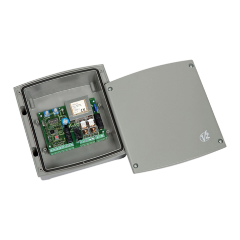
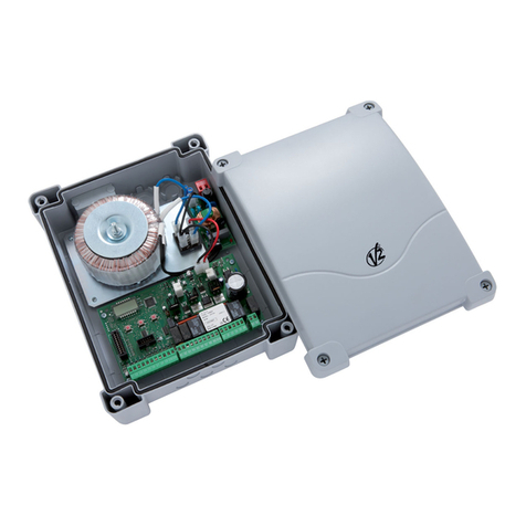
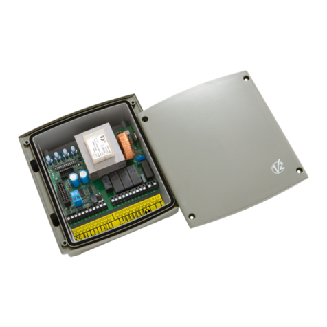
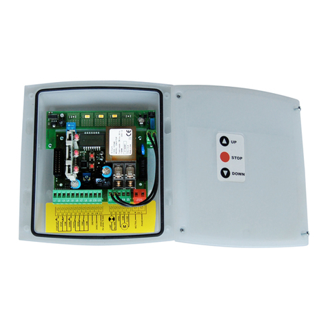
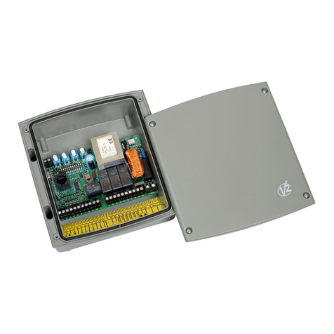
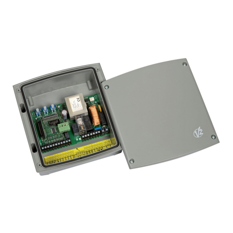
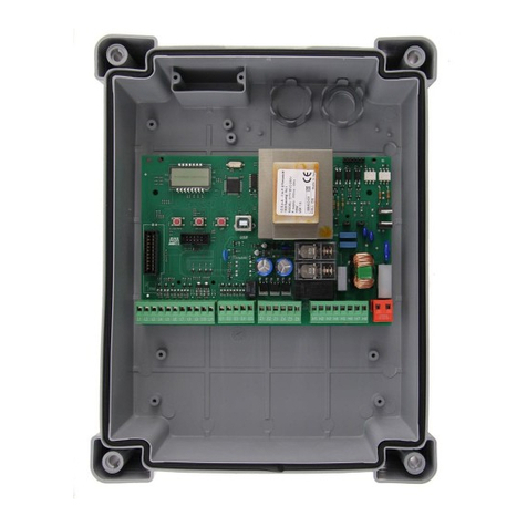
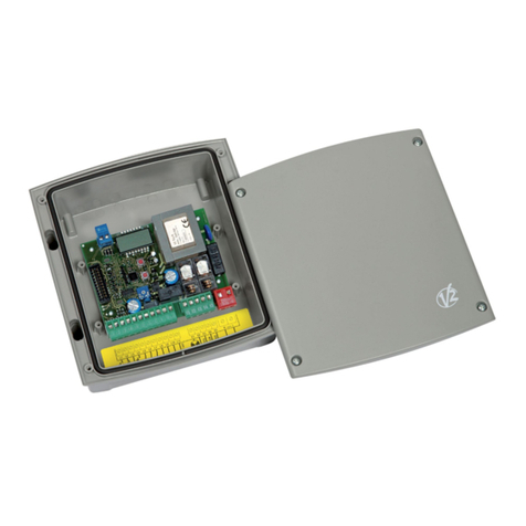
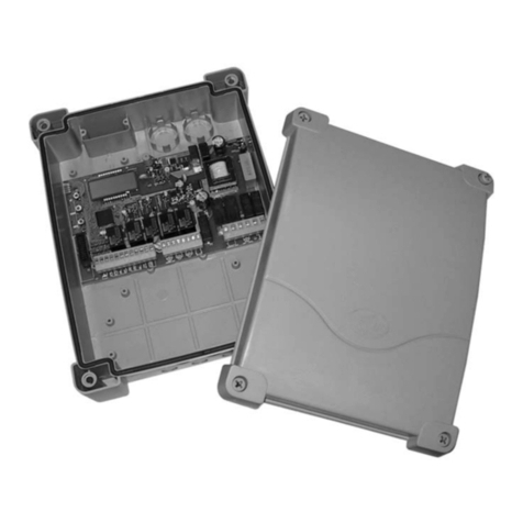
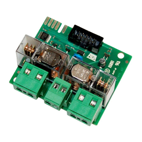
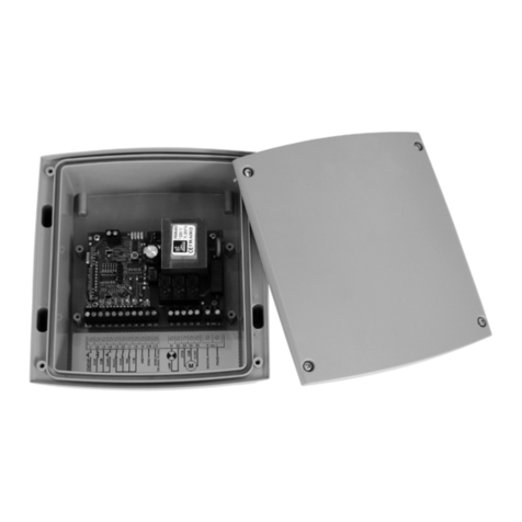
V2 CITY2+ User manual

ENGL SH
27
NDEX
IMPORTANT REMARKS . . . . . . . . . . . . . . . . . . . . . . . . . . . . . . . . . . . . . . . . . . . . . . . . . . . . . . . . . . . . . . . . . . . . . . . . .28
DECLARATION OF CONFORMITY . . . . . . . . . . . . . . . . . . . . . . . . . . . . . . . . . . . . . . . . . . . . . . . . . . . . . . . . . . . . . . . . .28
TECHNICAL SPECIFICATIONS . . . . . . . . . . . . . . . . . . . . . . . . . . . . . . . . . . . . . . . . . . . . . . . . . . . . . . . . . . . . . . . . . . . .28
DESCRIPTION OF THE CONTROL UNIT . . . . . . . . . . . . . . . . . . . . . . . . . . . . . . . . . . . . . . . . . . . . . . . . . . . . . . . . . . . . .28
INSTALLATION . . . . . . . . . . . . . . . . . . . . . . . . . . . . . . . . . . . . . . . . . . . . . . . . . . . . . . . . . . . . . . . . . . . . . . . . . . . . . . .29
POWER SUPPLY . . . . . . . . . . . . . . . . . . . . . . . . . . . . . . . . . . . . . . . . . . . . . . . . . . . . . . . . . . . . . . . . . . . . . . . . . . . . . .29
LOW VOLTA E OUTPUT . . . . . . . . . . . . . . . . . . . . . . . . . . . . . . . . . . . . . . . . . . . . . . . . . . . . . . . . . . . . . . . . . . . . . . . .29
COURTESY LI HTS . . . . . . . . . . . . . . . . . . . . . . . . . . . . . . . . . . . . . . . . . . . . . . . . . . . . . . . . . . . . . . . . . . . . . . . . . . . .29
PHOTOCELLS . . . . . . . . . . . . . . . . . . . . . . . . . . . . . . . . . . . . . . . . . . . . . . . . . . . . . . . . . . . . . . . . . . . . . . . . . . . . . . . .29
SAFETY RIBBONS . . . . . . . . . . . . . . . . . . . . . . . . . . . . . . . . . . . . . . . . . . . . . . . . . . . . . . . . . . . . . . . . . . . . . . . . . . . . .30
LOCK . . . . . . . . . . . . . . . . . . . . . . . . . . . . . . . . . . . . . . . . . . . . . . . . . . . . . . . . . . . . . . . . . . . . . . . . . . . . . . . . . . . . . .30
LIMIT SWITCH AND ENCODER . . . . . . . . . . . . . . . . . . . . . . . . . . . . . . . . . . . . . . . . . . . . . . . . . . . . . . . . . . . . . . . . . . .30
STOP . . . . . . . . . . . . . . . . . . . . . . . . . . . . . . . . . . . . . . . . . . . . . . . . . . . . . . . . . . . . . . . . . . . . . . . . . . . . . . . . . . . . . .31
ACTIVATION INPUTS . . . . . . . . . . . . . . . . . . . . . . . . . . . . . . . . . . . . . . . . . . . . . . . . . . . . . . . . . . . . . . . . . . . . . . . . . . .31
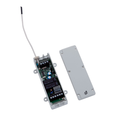
PLU IN RECEIVER . . . . . . . . . . . . . . . . . . . . . . . . . . . . . . . . . . . . . . . . . . . . . . . . . . . . . . . . . . . . . . . . . . . . . . . . . . . .31
EXTERNAL AERIAL . . . . . . . . . . . . . . . . . . . . . . . . . . . . . . . . . . . . . . . . . . . . . . . . . . . . . . . . . . . . . . . . . . . . . . . . . . . .32
ADI INTERFACE . . . . . . . . . . . . . . . . . . . . . . . . . . . . . . . . . . . . . . . . . . . . . . . . . . . . . . . . . . . . . . . . . . . . . . . . . . . . . .32
ELECTRIC CONNECTIONS TABLE . . . . . . . . . . . . . . . . . . . . . . . . . . . . . . . . . . . . . . . . . . . . . . . . . . . . . . . . . . . . . . . . .32
CONTROL PANEL . . . . . . . . . . . . . . . . . . . . . . . . . . . . . . . . . . . . . . . . . . . . . . . . . . . . . . . . . . . . . . . . . . . . . . . . . . . . .34
USE OF THE DOWN, MENU AND UP KEYS FOR PRO RAMMIN . . . . . . . . . . . . . . . . . . . . . . . . . . . . . . . . . . . . . . . . .34
QUICK CONFI URATION . . . . . . . . . . . . . . . . . . . . . . . . . . . . . . . . . . . . . . . . . . . . . . . . . . . . . . . . . . . . . . . . . . . . . . .34
LOADIN OF DEFAULT PARAMETERS . . . . . . . . . . . . . . . . . . . . . . . . . . . . . . . . . . . . . . . . . . . . . . . . . . . . . . . . . . . . . .34
SELF-LEARNIN OF WORKIN TIMES . . . . . . . . . . . . . . . . . . . . . . . . . . . . . . . . . . . . . . . . . . . . . . . . . . . . . . . . . . . . . .35
Obstacle sensor operation . . . . . . . . . . . . . . . . . . . . . . . . . . . . . . . . . . . . . . . . . . . . . . . . . . . . . . . . . . . . . . . . . . . . . .36
CONTROL UNIT CONFI URATION . . . . . . . . . . . . . . . . . . . . . . . . . . . . . . . . . . . . . . . . . . . . . . . . . . . . . . . . . . . . . . . .36
READIN OF CYCLE COUNTER . . . . . . . . . . . . . . . . . . . . . . . . . . . . . . . . . . . . . . . . . . . . . . . . . . . . . . . . . . . . . . . . . .48
OPERATION DEFECTS . . . . . . . . . . . . . . . . . . . . . . . . . . . . . . . . . . . . . . . . . . . . . . . . . . . . . . . . . . . . . . . . . . . . . . . . . .49
CITY2+ FUNCTION TABLE . . . . . . . . . . . . . . . . . . . . . . . . . . . . . . . . . . . . . . . . . . . . . . . . . . . . . . . . . . . . . . . . . . . . . . .50

ENGL SH
28
MPORTANT REMARKS
For any installation problem please contact our Customer Service
at the number +39-0172.812411 operating Monday to Friday
from 8:30 to 12:30 and from 14:00 to 18:00.
V2 has the right to modify the product without previous
notice; it also declines any responsibility to damage or
injury to people or things caused by improper use or
wrong installation.
Please read this instruction manual very carefully
before installing and programming your control unit.
• This instruction manual is only for qualified technicians,
who specialize in installations and automations.
• The contents of this instruction manual do not concern the
end user.
• Every programming and/or every maintenance service
should be done only by qualified technicians.
AUTOMAT ON MUST BE MPLEMENTED N COMPL ANCE
W TH THE EUROPEAN REGULAT ONS N FORCE:
EN 60204-1 (Machinery safety. electrical equipment of
machines, part 1: general rules)
EN 12445 (Safe use of automated locking devices,
test methods)
EN 12453 (Safe use of automated locking devices,
requirements)
• The installer must provide for a device (es. magnetotermical
switch) ensuring the omnipolar sectioning of the equipment
from the power supply.
The standards require a separation of the contacts
of at least 3 mm in each pole (EN 60335-1).
• After making connections on the terminal board, use one
hose clamp to fix dangerous voltage wires near the terminal
board and another hose clamp to fix safety low voltage wires
used for accessories connection; this way, in case of
accidental detachment of a conducting wire, dangerous
voltage parts will not come into contact with safety low
voltage ones.
• The plastic case has an IP55 insulation; to connect flexible
or rigid pipes, use pipefittings having the same insulation
level.
• Installation requires mechanical and electrical skills,
therefore it shall be carried out by qualified personnel only,
who can issue the Compliance Certificate concerning the
whole installation (EEC Machine Directive 89/392, Annex IIA).
• The automated vehicular gates shall comply with the
following rules: EN 12453, EN 12445, EN 12978 as well
as any local rule in force.
• Also the automation upstream electric system shall comply
with the laws and rules in force and be carried out
workmanlike.
• The door thrust force adjustment shall be measured
by means of a proper tool and adjusted according to
the max. limits, which EN 12453 allows.
• We recommend to make use of an emergency
button, to be installed by the automation (connected
to the control unit STOP input) so that the gate may
be immediately stopped in case of danger.
• Always remember to connect the earth according to
current standards (EN 60335-1, EN 60204-1).
DECLARAT ON OF CONFORM TY
V2 S.p.A. hereby declare that CITY2+ products conform to the
essential requirements established in the following directives:
- 89/336/CEE (EMC Directive in accordance with standards
EN 55014-1, EN 55014-2, EN 61000-3-2, 61000-3-3)
- 2006/95/CEE (Low Voltage Directive in accordance with
standards EN 60335-1 + EN 60335-2-103)
- 99/05/CEE (Radio Directive in accordance with standard
EN 301 489-3)
Racconigi, 12/01/2009
V2 S.p.A. legal representative.
Antonio Cristina
TECHN CAL SPEC F CAT ONS
DESCR PT ON OF THE CONTROL UN T
The digital control unit C TY2+ is an innovative V2 product that
guarantees a safe and reliable automation of leaf swing or
sliding gates.
C TY2+ is provided with a display that, not only makes
programming simple, but also allows a continuous monitoring of
the input statuses; in addition, thanks to a menu structure, the
working schedule and the operation logic can be set easily.
In compliance with the European standards concerning
electrical safety and electromagnetic compatibility
(EN 60335-1, EN 50081-1 and EN 50082-1) it has been
equipped with the low voltage circuit total electric insulation
(motors included) from the network voltage.
Other characteristics:
• Power supply protected from short circuits within the
controller, on the motors and on the connected accessories.
• Adjustment of the power by partializing the current.
• Detecting obstacles by monitoring the current on the motors
(current sensing probe)
• Automatic learning of the operation time.
• Tests for safety devices (photocells, safety ribbons and
mosfet) before each opening.
• Deactivation of safety inputs through the configuration
menu: no jumper is required for terminals concerning safety
devices that have not been installed, yet. You will only need
to disable this function from its relevant menu.
• The device can operate without mains power, by using the
optional battery pack (code 161212).
• Low voltage output that can be used for a signal light or a
24 V flashing light.
• Auxiliary relay with programmable logic for courtesy light,
flashing light or other use.
C TY2+
Power supply 230VAC - 50Hz
Max total load 250W
Max load for each motor 150W
Duty clcle 40%
Max accessories load 24Vdc 15W
Working temperature -20 ÷ +60°C
Protection fuse F1 = 2,5A
Dimensions 295 x 230 x 100 mm
Weight 3000g
Protection IP55

ENGL SH
29
NSTALLAT ON
Installation of control unit and safety devices must be carried out
with power disconnected.
POWER SUPPLY
The control unit must be fed by a 230V
50Hz (120V - 50/60Hz for the 120V
models) electric line, protected by a
differential magnetothermal switch
complying with the law
provisions in force.
Connect the power supply wires to
terminals Land Non the board located
next to the transformer.
LOW VOLTAGE OUTPUT
The CITY2+ controller has a 24 V DC output that allows
connections to a load up to 15 W.
This output can be used to connect a signal light that indicates
that status of the gate, or for a low voltage flashing light.
Connect the low voltage signal light or flashing light wires to
terminals Z1 (+) and Z2 (-).
CAUT ON: Pay attention to the polarity of the connected
device if necessary.
COURTESY L GHTS
Thanks to the output COURTESY LI HT the control unit
allows the connection of an electric appliance (e.g. courtesy
light or garden lights), controlled automatically or by means of
the special transmitter key.
The courtesy light terminals can be alternatively used for a 230 V
flashing light with integrated flasher.
CAUT ON: When the controller is operating on battery
power, the 230 V flashing light will not work.
The output COURTESY LI HT is a simple N.O. contact with no
power supply.
Connect the cables to terminals B1 and B2.
PHOTOCELLS
The control unit considers two kinds of photocells, depending on
the terminal to which they are connected:
•Photocell 1: that is to say, photocells installed on the gate
inner side, which are active both during the opening and the
closing phase. When photocells 1 operate, the control unit
stops the gate; as soon as the photocell beam is free, the
control unit will open the gate completely.
WARN NG: Type 1 photocells must be installed so that
they completely cover the opening area of the gate.
•Photocell 2: that is to say, photocells installed on the
external gate side and which are active during the closing
phase only. When photocells 2 operate, the control unit
opens the gate immediately, without waiting for release.
C TY2+ control unit supplies a 24Vdc power supply to photocells
and it can perform a photocell operation test before starting the
gate opening phase. Photocell power terminals are protected by
an electronic fuse that stops current in case of overload.
• Connect power supply cables of photocells transmitter
between terminals K7 and K8 of the control unit.
• Connect power supply cables of photocells receiver
between terminals K6 and K7 of the control unit.
• Connect receiver output of photocells 1 between terminals L7
and L11 of the control unit and receiver output of photocells
2 between terminals L8 and L11 of the control unit.
Use outputs having normally closed contact.
WARN NG:
• if several couples of same kind photocells are mounted,
their outputs must be connected in series.
• In case of reflection photocells, power supply must be
connected to terminals K7 and K8 of the control unit to
carry out the operation test.

ENGL SH
30
SAFETY R BBONS
The control unit considers two kinds of safety ribbons,
depending on the terminal to which they are connected:
•Type 1 (fixed): they are mounted on walls or on other fixed
obstacles that are approached by the gate doors during the
opening phase. When type 1 safety ribbons operate during
the gate opening phase, the control unit will close the doors
for 3 seconds, then it stands still; when type 1 safety ribbons
operate during the gate closing phase, the control unit will
stand still immediately. The direction of the gate at next
command of START or PEDESTRIAN START depends upon the
parameter STOP (it inverts or continues the motion).
If the input STOP is disabled, the command makes the motion
continue in the same direction.
•Type 2 (mobile): they are mounted to the door ends.
When type 2 safety ribbons operate during the gate opening
phase, the control unit will stand still immediately; when
type 2 safety ribbons operate during the gate closing, the
control unit will open the doors for 3 seconds, then it will
stand still. The direction of the gate at next command of
START or PEDESTRIAN START depends upon the parameter
STOP (it inverts or continues the motion). If the input STOP
is disabled, the command makes the motion continue in the
same direction.
Both the input can manage the classic safety edge with n.c.
contact and the conductive rubber safety edge with 8,2 kohm
nominal resistance.
Connect type 1 safety ribbons cables between terminals L9 and
L11 of the control unit.
Connect type 2 safety ribbons cables between terminals L10
and L11 of the control unit.
In order to meet the requirements of the EN12978 rules, it is
necessary to install safety edges controlled by a control unit
continuously checking the proper working. If using control units
suited to the test by power outage, connect the power supply
cables of the control unit between terminals K7 and K8 of the
control unit.
Otherwise, connect them between terminals K6 and K7.
WARN NG:
• Make use of safety ribbons having outputs with normally
close contact.
• Outputs of same kind safety ribbons must be connected in
series.
LOCK
An electric lock can be assembled on the gate, to ensure a good
closing of doors. Make use of a 12V lock.
Connect lock cables to terminals K9 and K10 of the control unit.
L M T SW TCH AND ENCODER
The CITY2+ controller can control the gate's travel using a limit
switch and/or an encoder.
CAUT ON: The use of these devices is strongly
recommended to ensure that the gate opens and closes
correctly.
The speed of operation of the DC motors can be conditioned by
variations in mains power, atmospheric conditions, and friction of
the gate.
Furthermore, encoders also allow the controller to determine if
the gate stops in an irregular position due to an obstacle.
For encoder operation, it is required that the closure position for
each section of the gate be detectable using a limit switch sensor
or a mechanical stop.
Each time the controller is turned on, to realign the encoders, the
gate is closed until it reaches the limit switch or the mechanical
stop.
GATES W TH TWO PANELS
For gates with two panels, limit switches and encoders share the
same terminals so it is not possible to install both of these devices
at the same time.
Installation of limit switch
• Connect the open limit switch to motor 1 using terminals
K1 and K5
• Connect the close limit switch to motor 1 using terminals
K2 and K5
• Connect the open limit switch to motor 2 using terminals
K3 and K5
• Connect the close limit switch to motor 2 using terminals
K4 and K5
Installation of encoders
• Connect the power source for both encoders to terminals
K5 and K6
• Connect the encoder outputs to motor 1 using terminals
K3 and K4
• Connect the encoder outputs to motor 2 using terminals
K1 and K2
Check that the two pairs of wires have been correctly connected
and after installation proceed as follows:
1. Disable encoder operation (Enco menu)
2. Set a meaningful open delay (r.AP menu)
NOTE: The default settings in the controller satisfy points
1 and 2.
3. ive a START command:
- If both gate panels move, the wires are connected correctly
- If Err7 appears on the display once panel 1 starts to move,
invert the wires connected to terminals K3 and K4
- If Err7 appears on the display once panel 2 starts to move,
invert the wires connected to terminals K1 and K2

ENGL SH
31
GATES W TH S NGLE PANELS
Installation of limit switch
• Connect the open limit switch to terminals K1 and K5
• Connect the close limit switch to terminals K2 and K5
Installation of encoder
• Connect the power source for the encoder to terminals
K5 and K6
• Connect the encoder output to terminals K3 and K4
Check that the two encoder wires have been correctly connected
and after installation proceed as follows:
1. Disable encoder operation (Enco menu)
2. Set a meaningful open delay (r.AP menu)
NOTE: The default settings in the controller satisfy points
1 and 2.
3. ive a START command:
- If the gate moves, the wires are connected correctly
- If Err7 appears on the display once the gate starts to move,
invert the wires connected to terminals K3 and K4
STOP
For a better safety, you can fit a stop switch that will cause the
immediate gate stop when activated. This switch must have a
normally close contact that will get open in case of operation.
In case the stop switch is operated while the gate is open, the
automatic closing function will always be disabled. To close the
gate again, you will need a start command (if the start function
in pause is disabled, it will be temporarily enabled to allow the
gate release).
Connect the stop switch cables between terminal L5 and L6 of
the control unit.
The stop switch function can be activated by means of a
remote control stored on channel 3 (see relevant instructions of
MR1 receiver) The command STOP from remote is operative
also if the input STOP of the terminal board is disabled.
ACT VAT ON NPUTS
C TY2+ control unit is equipped with two activation inputs,
whose operation depends on the programmed operation modes
(see Strt item of programming menu):
•Standard mode: a command being on the first input will
cause the complete opening of the gate (start); a command
being on the second input will cause the partial opening of
the gate (pedestrian start).
•Open/Close command and manned operation:
a command on the first input always controls the gate
opening, while a command on the second input always
controls the gate closing.
In Open/Close mode, there is an impulse command, that is
to say that an impulse will cause the complete gate opening
or closing.
In manned operation, there is a monostable command, that
is to say, the gate will be opened or closed as long as the
contact is closed and it will immediately stop as the contact
is open.
•Timer mode: it is similar to the standard mode but the gate
stays open (completely or partially) while the contact is
closed on input; as soon as the contact is open the pause
time count down will start, after which the gate will be
closed again. This function allows programming the gate
opening time during the day, by making use of an external
timer. Automatic closing must be enabled.
In all modes, inputs must be connected to devices having
normally open contacts.
Connect cables of device controlling the first input between
terminals L3 and L6 of the control unit.
Connect cables of device controlling the second input between
terminals L4 and L6 of the control unit.
The first input function can also be activated by pressing UP key
outside the programming menu or by means of a remote control
stored on channel 1 (see relevant instructions of MR1 receiver).
The second input function can also be activated by pressing
DOWN key outside the programming menu or by means of a
remote control stored on channel 2.
PLUG N RECE VER
C TY2+ control unit is suitable for plugging in a Personal Pass
MR1 receiver having a high-sensitivity super-heterodyne
architecture.
WARN NG: it is necessary to turn off the control unit
power before doing the operations mentioned here below. Pay
attention to the way you connect the removable modules.
MR1 module receiver is provided with 4 channels and each of
them is suitable for a command of C TY2+ control unit:
CHANNEL 1 쩚쩚쩛쩛START
CHANNEL 2 쩚쩚쩛쩛PEDESTRIAN START
CHANNEL 3 쩚쩚쩛쩛STOP
CHANNEL 4 쩚쩚쩛쩛COURTESY LI HT
WARN NG: Before programming 4 channels and function
logics read carefully the instructions of MR1.

ENGL SH
32
EXTERNAL AER AL
We suggest to use the external aerial (model: ANS P433) in
order to guarantee the maximal range.
Connect the antenna hot pole to terminal L1 of the control unit
and the braiding to terminal L2.
NTERFACE
The ADI (Additional Devices Interface) interface of the control
unit C TY2+ allows the connection to V2 optional modules.
Refer to V2 catalogue or to the technical sheets to see which
optional modules with ADI interface are available for this control
unit.
WARN NG: Please read the instructions of each single
module to install the optional modules.
L1 Antenna
L2 Antenna shield
L3 Opening control for the connection of control
devices with N.O. contact
L4 Opening controls for pedestrian access for the
connection of control devices with N.O. contact
L5 Stop command. N.C. contact
L6 Common (-)
L7 Photocells type 1. N.C. contact
L8 Photocells type 2. N.C. contact
L9 Safety ribbons type 1 (fixed). N.C. contact
L10 Safety ribbons type 2 (mobile). N.C. contact
L11 Common (-)
K1 Open limit switch motor 1
K2 Close limit switch motor 1
K3 Open limit switch motor 2
K4 Close limit switch motor 2
K5 Common (-)
K6 Power output +24Vdc for photocells and other
accessories
K7 Common for accessories power supply
K8 Photocell/optical edge TX power supply for
functional test
K9 - K10 LOCK 12V
Z1 - Z2 24 V courtesy light or flashing light
Z3 - Z4 Motor 1
Z5 - Z6 Motor 2
B1 - B2 230VAC courtesy light or flashing light
Interface
OVERLOAD It shows that there is an overload on accessories
power supply
BAT+ + Pole of optional battery pack (code 161212)
BAT- - Pole of optional battery pack (code 161212)
LPower phase 230 VAC / 120VAC
NNeutral 230 VAC / 120VAC
MA NS It shows that the control unit is power supplied
ELECTR C CONNECT ONS TABLE
Encoder motor 2
Encoder motor 1

ENGL SH

ENGL SH
34
CONTROL PANEL
When power is on, the control unit checks that display correctly
operates by switching on all segments for 1.5 sec. 8.8.8.8.
Firmware version, e.g. Pr I.0, will be viewed in the following 1.5
sec. Panel will be viewed upon completion of this test.
The control panel represents the physical status of the
terminal board contacts and of the program mode keys: if the
upper vertical segment is on, the contact is closed; if the lower
vertical segment is on, the contact is open (the above picture
shows an instance where the inputs LIMIT SWITCH, PHOTOCELL 1,
PHOTOCELL 2, SAFETY RIBBONS 1, SAFETY RIBBONS 2 and STOP
have all been correctly connected).
Points being among display digits show the status of
programming push-buttons: as soon as a push-button is pressed,
its relevant point turns on.
The arrows on the left of the display show the state of the start
inputs. The arrows light when the related input is closed.
The arrows on the display right side show the gate status:
• The highest arrow turns on when the gate is into its opening
phase. If it blinks, it means that the opening has been
caused by a safety device (border or obstacle detector).
• The central arrow shows that the gate is on pause. If it
blinks, it means that the time countdown for the automatic
closing has been activated.
• The lowest arrow blinks when the gate is into its closing
phase. If it blinks, it means that the closing has been
caused by a safety device (border or obstacle detector).
USE OF THE DOWN, MENU AND
UP KEYS FOR PROGRAMM NG
Programming of the functions and times of the controller is
performed using a special configuration menu that is accessed and
explored using 3 keys, DOWN, MENU, and UP, which are located
below the display.
CAUT ON: Except in the configuration menu, pressing the
UP key activates a START command and pressing the DOWN
key activates a START PEDESTR AN command.
To activate the programming modes (the display must show the
control panel), press and hold down the MENU key until -PrG
appears on the display.
Hold down the MENU key to scroll through the 4 main menus:
-PrG CONTROLLER PRO RAMMIN
-Cnt COUNTERS
-APP SELF-LEARNIN TIME AND FORCE
-dEF LOAD DEFAULT PARAMETERS
To enter one of the four main menus, just release the MENU key
when the menu you want appears on the display.
To move through the four main menus, press the UP and DOWN
keys to scroll through the various items. Press the MENU key to
display the current value of the selected item and change it if
needed.
QU CK CONF GURAT ON
This paragraph concerns a quick procedure to set the control unit
and set it at work immediately.
We recommend following these instructions, in order to
check quickly the correct operation of control unit, motor
and accessories, and then changing the configuration in
case of any non-satisfactory parameter.
1. Call up the default configuration: see paragraph “LOADIN
OF DEFAULT PARAMETERS”
CAUT ON: If there is only one motor, set the open time, t.AP2,
to zero in order to inform the controller that the parameters for
motor 2 do not need to be considered.
2. Set items StoP, Fot1, Fot2, CoS1, CoS2 according to the
safety devices installed on the gate.
3. Start the self-learning cycle: see paragraph “SELF-LEARNIN
OF WORKIN TIMES “
4. check that the automation work properly and if necessary
modify the configuration of the desired parameters. For the
position of the item menus inside the main menu and for the
options related to each item menu, refer to the paragraph
“CONFI URATION OF THE CONTROL UNIT”.

ENGL SH
35
LOAD NG OF DEFAULT
PARAMETERS
If necessary, it is possible to restore all the parameters to their
standard or default value (see table at the end)
WARN NG: This procedure causes the loss of all the
customized parameters, therefore it has been put outside the
configuration menu, to reduce the possibility of executing it by
mistake.
1. Press and hold down the MENU key until the -dEF appears
on the display
2. Release the MENU key: the display will show ESC (press the
MENU key only if you want to leave this menu)
3. Press the DOWN key: dEF will appear on the display.
4. Press the MENU key: no will appear on the display.
5. Press the DOWN key: Si will appear on the display.
6. Press the MENU key: All of the parameters are returned to
their default values and the display shows the control panel
SELF-LEARN NG OF WORK NG
T MES
This menu allows the automatic learning of the times necessary
to open and close the gate.
During this phase, the control unit memorizes also the forces
necessary to open and close the gate: these values will be
activated by using the obstacle sensor.
The encoder positions are also saved, if enabled.
CAUT ON: Before continuing, make certain that the
limit switch(es) and encoder(s) have been installed
correctly. Limit switches and encoders, if installed, must be
enabled using the specific menu.
1. Press and hold down the MENU key until the -APP appears on
the display
2. Release the MENU key: the display will show ESC (press the
MENU key only if you want to leave this menu)
3. Press the DOWN key: t.LAv will appear on the display.
4. Press the MENU key to start the self-learning cycle for the
work cycle times:
CAUT ON: This procedure varies based on the number of gate
panels and travel control devices installed.
If there is no limit switch or encoder installed, only points 4.4
and 4.5 are performed. If there is only one motor (t.AP2 = 0),
the procedure starts from point 4.3
4.1 ate panel 1 is opened for a few seconds
4.2 ate panel 2 is closed until one of the following
conditions occurs:
- it reaches the limit switch
- The obstacle sensor or the encoder detect that the
gate panel is jammed
- A START command is given
This position is memorized as the close point for gate
panel 2.
4.3 ate panel 1 is closed until one of the conditions listed
in point 4.2 occur:
This position is memorized as the close point for gate
panel 1.
4.4 Each gate panel is opened. The operation ends when
once of the conditions indicated in point 4.2 occur (the
first START stops gate panel 1, the second START stops
gate panel 2).
The time required is memorized as the open time.
4.5 Each gate panel is closed. The operation ends when one
of the conditions indicated in point 4.2 occurs or when
the closed position is reached.
The time required is memorized as the close time.
5. The display shows the value recommended for the obstacle
sensor of motor 1. If no operations are performed for
20 seconds, the controller exits the programming phase
without saving the recommended value.
6. The recommended value can be changed using the UP and
DOWN keys. Press the MENU key to confirm the value
displayed and the display will show SEn1
7. Press the DOWN key: The display will show SEn2. Press the
MENU key to display the recommended value for the obstacle
sensor for motor 2, which can be changed in a similar manner
as that for SEn1.
8. Hold down the DOWN key until the FinE appears on the
display, then press the MENU key, select Si and press the
MENU key to exit programming and save the values for the
sensors.
CAUT ON: If the controller exits programming due to time out
(1 minute), the obstacle sensors return to the values that were
set prior to performing self-learning.
The open/close times and the encoder positions are always
saved.

ENGL SH
36
OBSTACLE SENSOR OPERAT ON
C TY2+ control unit is equipped with a sophisticated system that
allows detecting if there is any obstacle stopping the gate
motion. This system is based on the measurement of the current
absorbed by the motor: a sudden increase of the absorption
indicates the presence of an obstacle.
CAUT ON: The obstacle sensor is disabled by default and must
be enabled using the specific menu items, SEn1 and SEn2.
Detection is performed at both normal speed and slow speed.
The threshold of the sensor is automatically adjusted.
WARN NG: if either the limit switches or the slowing down are
disabled, when detected an obstacle the control unit stops the
opening or closing phase without inverting the motion.
CONTROL UN T
CONF GURAT ON
The configuration menu -PrG consists in a list of configurable
items; the display shows the selected item.
By pressing DOWN, you will pass to the next item; by pressing
UP, you will return to the previous item.
By pressing MENU, you can view the current value of selected
item and possibly change it.
The last menu item (FinE) allows storing the carried out
changes and going back to the control unit normal operation.
You must exit from programming mode through this menu item
if you do not want to lose your configuration.
WARN NG: in case no operation is carried out for more
than one minute, the control unit exits from the
programming mode without saving any of your setups and
changes, which will get lost.
By holding down the DOWN key, configuration menu items will
scroll fast, until item FinE is viewed. Viceversa, by holding down
the UP key, items will scroll fast backwards until item t.AP1 is
viewed.
In this way, you can quickly reach either the top or
bottom of the list.
There are the following three kinds of menu items:
• Function menu
• Time menu
• Value menu
Function menu setup
Function menus allow selecting a function from among a group
of available options. When you enter into a function menu, the
current active option will be viewed; you can scroll all available
options through DOWN and UP keys. By pressing the MENU key,
you will activate the option viewed and you will return to the
configuration menu.
Time menu setup
Time menus allow setting a function duration. When you enter
into a time menu, the current setup value will be viewed; the
display mode depends on the current value:
• times being lower than one minute will be viewed as follows:
each time you press UP key, current time value increases of
half a second; vice versa, each time you press the DOWN
key, current time value decreases of half a second.
• Times between 1 and 10 minutes will be viewed as follows:
each time you press UP key, current time value increases of 5
seconds; vice versa, each time you press the DOWN key,
current time value decreases of 5 seconds.
• Times being more than 10 minutes will be viewed as follows:
each time you press UP key, current time value increases of
half a minute; vice versa, each time you press the DOWN key,
current time value decreases of half a minute.
By holding down the UP key, you can quickly increase the time
value, up to reach the max. value allowed for this item. Vice
versa, by holding down the DOWN key, you can quickly decrease
the time value down to reach 0.0”.
In some circumstances, setting the value to 0 means that the
relevant function is disabled, in this case, ‘no’ will appear instead
of 0.0”.
By pressing on MENU you will confirm the displayed value and
you will return to the configuration menu.
Value menu setup
Value menus are similar to time menus; however, the setup value
can be any number.
By holding down UP or DOWN keys, the value will increase or
decrease slowly.

ENGL SH
37
Leaf 1 opening time
Motor 1 will be operated for the setup time in the opening phase;
in case there is an obstacle or the end of stroke operates, the control
unit can stop the opening phase before the relevant time expires.
Leaf 2 opening time
Motor 2 will be operated for the setup time in the opening phase;
In case there is an obstacle or the end of stroke operates, the control
unit can stop the opening phase before the relevant time expires.
WARN NG: if motor 2 is not connected, this time must be set to
zero; in this circumstance, the control unit will not consider all
configurations of motor 2 and door phase difference times as well.
Partial opening time (pedestrian access)
When the control unit receives a Start Pedestrian command, it will open
leaf 1 only, for a shorter time. Max allowed time to be setup is
1 minute.
Leaf 1 closing time
Motor 1 will be operated for the setup time in the closing phase;
In case there is an obstacle or the end of stroke operates, the control
unit can stop the opening phase before the relevant time expires.
To avoid that the door does not close completely, we recommend to
setup a longer time than t.AP1 opening time.
Leaf 2 closing time
Motor 2 will be operated for the setup time in the closing phase;
the control unit can stop the opening phase before the relevant time
expires, in case there is an obstacle or the end of stroke operates.
To avoid that the door does not close completely, we recommend to
setup a longer time than t.AP2 opening time.

ENGL SH
38
Partial closing time (pedestrian access)
When the control unit receives a Start Pedestrian command, it will use
this time to close the gate. Max allowed time to be setup is 1 minute.
To avoid that the door does not close completely, we recommend to
setup a longer time than t.APP opening time.
Leaf 2 closing time during pedestrian cycle
During a partial opening cycle (pedestrian access) leaf 2 may move
slightly because of the wind or its own weight; in this case at closing
time leaf 1 could hit leaf 2 and the gate would remain not perfectly
closed.
To avoid this, in the last seconds of the cycle a light closing force is
applied to leaf 2 too. If the set time is greater than the time required to
close leaf 1, leaf2 is driven at reduced power all the closing time long.
Opening door delay
During the opening phase, leaf 1 must start moving before leaf 2, to
avoid that both doors may collide. Leaf 2 opening will be delayed for
the setup time.
If you set the opening door delay to zero, the control board does not
execute the control of the correct leaves closing order.
Closing door delay
During the closing phase, leaf 1 must start moving after leaf 2, to avoid
that both doors may collide. Door 1 closing will be delayed for the setup
time.
Lock time
Before the opening phase begins, the control unit will energize the
electric lock in order to release it and enable the gate motion.
t.SEr time will fix the energizing time.
WARN NG: in case the gate has no electric lock, set the value 0
(‘no’ will appear on display).

ENGL SH
39
Silent Locking Mode
This menu allows you to select the silent operation mode for the electric
lock.
Si Silent Mode (100 Hz)
no Standard Mode (50 Hz)
CAUT ON: In silent mode, the voltage supplied to the lock has a higher
frequency in order to make the locking less noisy.
In some cases, there may be problems when unlocking. If problems
should occur, select the Standard mode.
Lock advance time
While the electric lock is energized, the gate will stay standstill for t.ASE
time, to make its release easier.
In case t.ASE is lower than t.SEr, the lock energizing will go on while
the doors will start moving.
WARN NG: in case the gate has no electric lock, set the value 0.
Backlash time
It could be useful to give a closing command to motors, to help the
electric lock release.
The control unit controls the motors in reduced power in closing
direction for the setup time.
The backlash precedes the electric lock release. It is possible to reverse the
order by setting a lock advance time higher then the backlash one.
WARN NG: in case the gate has no electric lock, set the value 0.
Pre-blinking time
Before any gate movement, blinker will be activated for t.PrE time, to
warn about the incoming motion.
Motor 1 power
This menu allows adjusting the motor 1 power.
The displayed value is the percentage of max. motor power.

ENGL SH
40
Motor 2 power
This menu allows adjusting the motor 2 power.
The displayed value is the percentage of max. motor power.
Power Motor 1 during slow-down phase
This menu allows you to regulate the power of motor 1 during the
slow-down phase.
The value displayed represents the percentage of the maximum motor
power.
Power Motor 2 during slow-down phase
This menu allows you to regulate the power of motor 2 during the
slow-down phase.
The value displayed represents the percentage of the maximum motor
power.
Start off
When the gate is standstill and it begins moving, the initial inertia must
be faced, therefore, if your gate is quite heavy, its doors could not
move.
In case the SPUn (pickup) function is activated, for the first 2 seconds of
motion of each door, the control unit will ignore both Pot1 and Pot2
values and it will give motors the maximum power command in order to
overcome the gate inertia.
Maximum motor power during battery operation
During battery operation, the controller is powered with a lower voltage
compared to mains power. For this reason, the power of the motors is
reduced compared to normal operation and may not be sufficient to
move the gate panels effectively.
This menu allows you to activate the motors at their maximum power
during battery operation.
Si Maximum motor power
no Motor power at the parameters set in the Pot1
and Pot2 menus.

ENGL SH
41
Starting ramp
In order not to stress too much the motor, when the motion starts the
power is gradually increased, until reached the set value or 100% if the
take-off is enabled.
Higher is the set value, longer the length of time of the ramp, that is the
time necessary to reach the value of nominal power.
Enable the Obstacle Sensor for Motor 1
This menu allows you to regulate the sensitivity of the obstacle sensor
for motor 1. When the current absorbed by the motor exceeds the set
value, the controller detects an alarm.
If set to 0.0A, this function is disabled.
For the sensors operation, please see the paragraph dedicated to it
(page 36).
Enable the Obstacle Sensor for Motor 2
This menu allows you to regulate the sensitivity of the obstacle sensor
for motor 2. When the current absorbed by the motor exceeds the set
value, the controller detects an alarm.
If set to 0.0A, this function is disabled.
For the sensors operation, please see the paragraph dedicated to it
(page 36).
Slowing down time
In case this function is enabled, during the last seconds of motion of
each door, the control unit will give motors a reduced power command,
to avoid a strong impact with the stop end. t.AP1 is the max. allowed
time.
WARN NG:
• In case the self-learning function of working times is NOT used, we
recommend disabling the slowing down function in order to
measure both opening and closing times, and to enable it again once
the setup has been carried out. The control unit will automatically
consider the working time delay caused by the slowing down.
• If partial opening time t.APP is shorter than t.AP1, there will be no
slowing down during the pedestrian cycle opening.
Fast closing time after slowing down
If a slowing time other than 0 is set up, it could be likely that the gate
speed is not enough for the lock to fasten during the closing phase.
In case this function is enabled, once the slowing down phase is
finished, the control unit will give a normal speed command (that is to
say, with no slowing down) for the set up time, and then it will open
the gate for a second fraction, to avoid leaving the motor under stress.
WARN NG: in case the gate has no electric lock, set the value 0.

ENGL SH
42
Start command during the opening phase
This menu allows fixing the control unit conduct in case it receives a
Start command during the opening phase.
PAUS The gate stops and goes to pause.
ChiU The gate immediately starts closing.
no The gate go on with the opening phase (command is ignored).
Select option PAUS, to set up the “step-by-step” operation logic.
Select option ‘no’, to set up the ‘always open’ operation logic.
Start command during the closing phase
This menu allows fixing the control unit conduct in case it receives a
Start command during the closing phase.
StoP The gate stops and its cycle is considered as finished.
APEr The gate opens again.
Select option StoP, to set up the “step-by-step” operation logic.
Select option APEr, to set up the ‘always open’ operation logic.
Start command during the pause
This menu allows fixing the control unit conduct in case it receives a
Start command when the gate is open during its pause phase.
ChiU the gate starts closing.
no command is ignored.
PAUS The pause time is reset (Ch.AU)
Select option ChiU, to set up the “step-by-step” operation logic.
Select option ‘no’, to set up the ‘always open’ operation logic.
Apart from selected option, the start command lets the gate close if it
has been stopped by a stop command or if the automatic closing was
not enabled.
Pedestrian Start during the partial opening phase
This menu allows fixing the control unit conduct in case it receives a
Pedestrian Start command during the partial opening phase.
PAUS The gate stops and goes to pause.
ChiU the gate immediately starts closing.
no the gate goes on with the opening phase (command is ignored).
WARN NG: a Start command in any phase of partial opening will
cause the total opening; the Start Pedestrian command is always
ignored during a total opening.

ENGL SH
43
Automatic closing
During the automatic operation, the control unit will automatically close
the gate when a set-up time expires.
The Start command, if enabled by St.PA menu, allows closing the gate
before the set up time expires.
In semi-automatic operation, that is to say, if the automatic closing
function is disabled by setting the value to zero ('no' will be displayed),
the gate can be closed through the start command only: in this case,
St.PA menu setup will be ignored.
If the control unit receives a Stop command when the gate is in pause,
it will automatically pass to the semi-automatic operation.
Closing after transit
During the automatic operation, the pause count down starts from the
set up value each time a photocell operates during the pause.
If the photocell operates during the opening time, this time will be
immediately stored as pause time.
This function allows having a fast closing as soon as transit through the
gate is completed, therefore, a time shorter than Ch.AU is
generally used.
Ch.AU will be used when ‘no’ is set up.
As for semi-automatic operation, this function is not active.
Pause after transit
In order to let the gate open for the shortest possible time, it is possible
to stop the gate once the passage before the photocells is detected. If
the automatic working is enabled, the time of the pause is Ch.tr.
If the photocells are type 1 and type 2, the gate enters the phase of
pause only after the detections before both the photocells.
Courtesy lights
This menu allows setting the automatic operating of the courtesy
lights during the opening cycle of the gate.
NOTE: If the output is used to drive a flashing light (with internal
flasher) select CiCL.
t.LUC the relay is enabled at the receiving of a control of start
or pedestrian start; choosing this option, a submenu is
entered – it allows to set the length of the activation of
the relay from 0.0” to 20’0 (default 1’00). At the time
limit, the relay is disabled.
no the relay of the courtesy lights is not automatically
activated
CiCL the relay is activated during the motion of the gate;
when the gate stops (closed or open) the relay is on all
the time t.LUC long (set in the submenu t.LUC)
If the option LP.PA is activated, the relay is on also
during the pause time

ENGL SH
44
Auxiliary channel
This menu allows setting the operating of the relay of the lighting of the
courtesy lights by means of a remote control stored on the channel 4 of
the receiver.
tiM the relay is activated receiving the transmission of the
remote control; it is disabled after the time set for the
parameter t.LUC inside the menu LUCi
Mon the relay is activated for all the length of the
transmission of the remote control. Releasing the key of
the remote control the relay is deactivated
biSt the status of the relay changes at each transmission of
the remote control
Low Voltage Output Setup
This menu allows you to set the operation of the low voltage output.
no Not used
FLSh Flasher operation (fixed frequency)
WL Indicator light operation: Indicates the status of the gate in
real-time. The type of blinking indicates the four possible
conditions:
- ATE STOPPED: Light off
- ATE IN PAUSE: the light is on, fixed
- ATE OPENIN : the light blinks slowly (2 Hz)
- ATE CLOSIN : the light blinks quickly (4 Hz)
Blinker during pause time
Blinker usually operates during the gate motion only; however, if this
function is enabled, blinker will be on during the pause time too.
The flasher may be either in the device connected to the LUCI output
(setting the CiCL parameter in the LUCi menu) or the device connected
to the low voltage output (setting the FLSh parameter in the SPiA
menu).
Start input function
This menu allows selecting input operation modes (see paragraph
“Activation inputs”):
StAn Start and Pedestrian Start input standard operation,
according to menu setups.
no Start inputs from terminal board are disabled. Radio inputs
operate in StAn mode.
AP.CH Start impulse always controls the opening phase, Pedestrian
Start always controls the closing phase.
PrES Manned operation; the gate will open as long as the Start
input stays closed and it will close as long as Pedestrian
Start stays closed.
oroL Timer-operation; the gate stays open while the Start input or
Pedestrian Start input is closed; as soon as the contact
opens, the pause count down will start.

ENGL SH
45
Stop nput
This menu permits to select the functions associated to the
command of STOP.
no The input STOP is not available.
ProS The input STOP stops the gate: pressing the command START
the gate continues the motion.
invE The command STOP stops the gate: at the next START the
gate starts moving in the opposite direction.
The setting of parameter STOP determines also in which direction the
gate will move at the next START, if it has stopped because of an
intervention of the safety edges or the obstacle sensor. If you set no, the
START command restarts the motion in the same direction.
NOTE: during the pause, the STOP command will stop the pause time
count, the next START command will always close the gate.
Photocell 1 input
This menu allows enabling the input for type 1 photocells, that is to say,
photocells active both during the opening and closing phase (see
paragraph “Installation”).
no Input disabled (ignored by the control unit).
No jumper with the common is required.
AP.CH Input enabled.
Photocell 2 input
This menu allows enabling the input for type 2 photocells, that is to say,
photocells non active during the opening phase (see paragraph
“Installation”).
no Input disabled (ignored by the control unit).
No jumper with the common is required.
CF.CH Input enabled even at standstill gate too: the opening
movement does not start if photocell is interrupted.
CH Input enabled for the closing phase only.
Warning: if you select this option, you must disable photocell
test.
Test of the photocells
In order to achieve a safer operation for the user, the unit performs a
photocells operational test, before a normal working cycle.
If no operational faults are found, the gate starts moving.
Otherwise, it will stand still and the flashing light will stay onfor 5 sec.
The whole test cycle lasts less than one second
WARN NG: V2 suggests to keep activated the test of the
photocells in order to grant a higher safety of the system.

ENGL SH
46
Safety ribbon 1 input
This menu allows enabling the input for type 1 safety ribbon, that is to
say, fixed ribbons (see paragraph “Installation”).
no input disabled (ignored by the control unit).
AP Input enabled during the opening and disabled during the
closure
APCH Input enabled in opening and closure
Safety ribbon 2 input
This menu allows enabling the input for type 2 safety ribbon, that is to
say mobile ribbons (see paragraph “Installation”).
no input disabled (ignored by the control unit).
No jumper with the common is required.
Ch Input enabled during closure and disabled during opening
APCH Input enabled in opening and closure
Test of the safety edges
This menu allows setting the method of control of the safety edges
working.
no Test disabled
Foto Test enabled for optical safety edges
rESi Test enabled for conductive rubber safety edges
WARN NG: V2 suggests to keep activated the test of the
photocells in order to grant a higher safety of the system.
End of Stroke nputs
The CITY2+ controller permits the connection of 4 normally closed (NC)
limit switches that are activated by the gates movement and indicate to
the controller if the gate has reached the completely open or closed
position.
Si end of stroke inputs are enabled
no end of stroke inputs are disabled
Other manuals for CITY2+
2
Table of contents
Other V2 Control Unit manuals
Popular Control Unit manuals by other brands

Urrea
Urrea 23615 User manual and warranty

X2E
X2E XORAYA DATACUBE-N1 user manual

Bardiani Valvole
Bardiani Valvole BBZO Instruction, use and maintenance manual

Sauter Components
Sauter Components LRA 4 Series quick start guide

Trenz Electronic
Trenz Electronic TE0726 Schematics

Advantech
Advantech USB-4716 user manual