Landoll 3210 Series User manual

MODEL 3210 SERIES
MULCHER
OPERATOR’S MANUAL
1900 NORTH STREET
MARYSVILLE, KANSAS 66508
(785) 562-5381
F-340-1106 11/06


MODEL 3210 SERIES
MULCHER
OPERATOR’S MANUAL
PURCHASED FROM: DATE / /
ADDRESS:
PHONE NO.: SERIAL NO.:
i

TABLE OF CONTENTS
SECTION DESCRIPTION PAGE NO.
1 INTRODUCTION 1-1
2 STANDARD SPECIFICATIONS 2-1
3 ASSEMBLY INSTRUCTIONS 3-1
3-1 ASSEMBLY - SAFETY ................................3-1
3-2 AFTER ASSEMBLY - SAFETY...........................3-3
3-3 ASSEMBLY INSTRUCTIONS ............................3-3
3-4 ROLLER GANG, TRANSPORT AXLE, AND
FRAME ASSEMBLY - 10’ - 15’ MODELS ...................3-7
3-5 MAIN FRAME ASSEMBLY - 18’ MODEL ...................3-9
3-6 TOOTH BAR ASSEMBLY - 10’ - 15’ MODELS ..............3-10
3-7 TOOTH BAR ASSEMBLY - 18’ MODELS ..................3-11
3-8 TONGUE ASSEMBLY - 10’ MODEL ......................3-12
3-9 TONGUE ASSEMBLY - 12’ MODEL ......................3-13
3-10 TONGUE ASSEMBLY - 13’ - 15’ MODELS .................3-14
3-11 TRANSPORT LEVELER - 18’ MODEL ....................3-15
3-12 LINKAGE ASSEMBLY - 10’ - 15’ MODELS ................3-16
3-13 HYDRAULIC ASSEMBLY..............................3-17
3-14 TRANSPORT LOCK - 10’ - 15’ MODELS ..................3-18
3-15 ELECTRICAL INSTALLATION ..........................3-22
3-16 TRANSPORT CHAIN .................................3-23
3-17 INDEPENDENT HYDRAULIC TOOTH CONTROL
- 10’ MODEL (OPTIONAL) .............................3-23
3-18 INDEPENDENT HYDRAULIC TOOTH CONTROL
- 12’ - 15’ MODELS (OPTIONAL) ........................3-24
3-19 INDEPENDENT TOOTH CONTROL - 18’ MODEL (OPTIONAL) . . 3-25
3-20 SCRAPERS (OPTIONAL)..............................3-26
3-21 REAR HITCH - 10’ - 15’ MODELS (OPTIONAL) .............3-27
3-22 LAND LEVELER - 10’ - 15’ MODELS (OPTIONAL) ...........3-28
3-23 LAND LEVELER - 18’ MODEL (OPTIONAL) ................3-29
3-24 WEED WIPER (OPTIONAL) ............................3-30
ii

4 OPERATION AND MAINTENANCE 4-1
4-1 DECALS ...........................................4-5
4-2 TRACTOR REQUIREMENTS ............................4-5
4-3 TRACTOR PREPARATION .............................4-6
4-4 MULCHER PREPARATION .............................4-6
4-5 ATTACHING TO TRACTOR .............................4-7
4-6 UNHITCHING FROM TRACTOR..........................4-7
4-7 FIELD OPERATION...................................4-8
4-8 HITCH ADJUSTMENT .................................4-8
4-9 AUTOMATIC TRANSPORT LOCK ........................4-9
4-10 ROLLERS .........................................4-10
4-11 SCRAPERS........................................4-10
4-12 SPRING TINE DEPTH ADJUSTMENT.....................4-11
4-13 TINE BAR RETAINER PLACEMENT .....................4-11
4-14 SPRING TINE ROTATIONAL ADJUSTMENT ...............4-12
4-15 ELECTRICAL SYSTEM AND REFLECTORS................4-13
4-16 SPRING TINES .....................................4-13
4-17 TRANSPORTING THE MULCHER .......................4-14
4-18 GENERAL MAINTENANCE ............................4-14
4-19 LUBRICATION .....................................4-15
5 TROUBLESHOOTING GUIDE 5-1
iii

SAFETY PRECAUTIONS
THIS IS THE SAFETY ALERT SYMBOL. IT IS USED TO ALERT YOU
TO POTENTIAL INJURY HAZARDS. OBEY ALL SAFETY MESSAGES
THAT FOLLOW THIS SYMBOL TO AVOID POSSIBLE INJURY OR
DEATH.
DANGER DANGER INDICATES AN IMMINENTLY HAZARDOUS SITUA-
TION WHICH, IF NOT AVOIDED, WILL RESULT IN DEATH OR
SERIOUS INJURY.
WARNING WARNING INDICATES A POTENTIALLY HAZARDOUS SITUA-
TION WHICH, IF NOT AVOIDED, COULD RESULT IN DEATH OR
SERIOUS INJURY.
CAUTION CAUTION INDICATES A POTENTIALLY HAZARDOUS SITUA-
TION WHICH, IF NOT AVOIDED, MAY RESULT IN MINOR OR
MODERATE INJURY.
CAUTION CAUTION USED WITHOUT THE SAFETY ALERT SYMBOL INDI-
CATES A POTENTIALLY HAZARDOUS SITUATION WHICH, IF
NOT AVOIDED, MAY RESULT IN PROPERTY DAMAGE.
iv

1INTRODUCTION
The Landoll 3210 Series Mulcher is a quality product designed to give years of trouble free perform-
ance. By following each section of this manual, your system will perform as designed for you and your op-
eration.
SECTION 1 gives basic instructions on the use of this manual.
SECTION 2 gives product specifications. These specifications supply lengths and measures for your
equipment. A Standard Bolt Torque Table is provided to give guidelines for bolt torques
to be used when servicing this product.
SECTION 3 contains assembly instructions for your 3210 Series Mulcher. When these procedures
are correctly followed, your equipment should provide you years of trouble-free opera-
tion and service.
SECTION 4 instructs how to operate your equipment before using it, and describes adjustments
needed. It also gives practical advice for the care and maintenance of your Landoll
equipment. Drawings in this section locate adjustment points on the equipment.
NOTE: IF THE EQUIPMENT IS IMPROPERLY ASSEMBLED OR MAINTAINED, THE
WARRANTY IS VOID. IF YOU HAVE ANY QUESTIONS CONTACT:
LANDOLL CORPORATION
1900 NORTH STREET
MARYSVILLE, KANSAS 66508
or phone:
(785) 562-5381 or
(800) 428-5655
or FAX:
(785) 562-4893
SECTION 5 is a troubleshooting guide to aid in diagnosing and solving problems with the equip-
ment.
PARTS LIST is a separate manual showing the various assemblies, subassemblies, and systems.
Refer to that manual when ordering Landoll replacement parts. Order parts from your
Landoll dealer.
WARRANTY The Warranty Registration form is included with the product documents. Fill it out and
mail it within 15 days of purchase. The Warranty is printed inside the front cover.
NOTE: IMPROPER ASSEMBLY, MODIFICATION, OR MAINTENANCE OF YOUR
LANDOLL EQUIPMENT CAN VOID YOUR WARRANTY.
COMMENTS Address comments or questions regarding this publication to:
LANDOLL CORPORATION
1900 NORTH STREET
MARYSVILLE, KANSAS 66508
ATTENTION: PUBLICATIONS -DEPT. 55
1-1


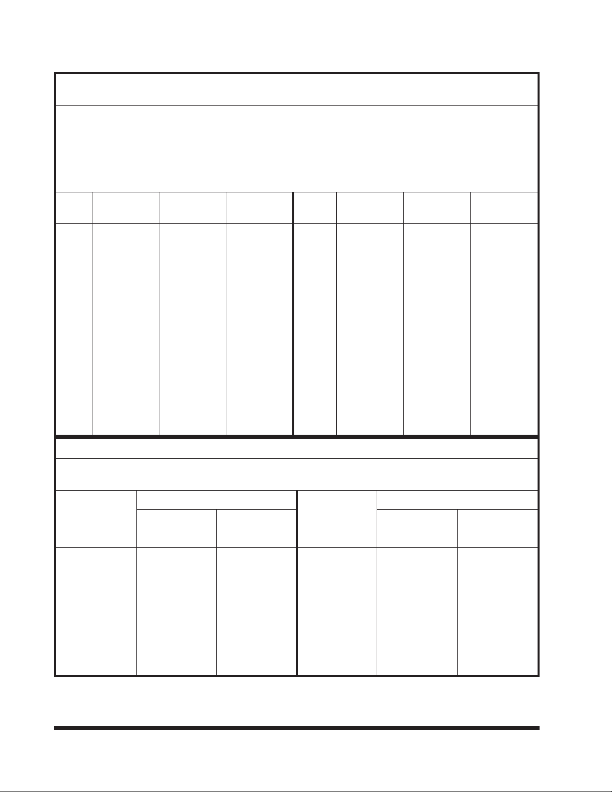
2STANDARD SPECIFICATIONS
MACHINE TYPE ROLLING
WIDTH
TRANSPORT
WIDTH
ROLLER
QTY. PER
MACHINE
DRAWBAR
HP
APPROXIMATE
WEIGHT (Lbs.)
Machine w/ 17” Smooth Rollers
Front and Rear
10’-1” 10’-7” 56 50 4,048
12’-2” 12’-10” 68 60 5,000
13’-2” 13’-10” 72 65 5,300
14’-2” 14’-10” 78 70 5,535
15’-3” 15’-11” 84 75 5,790
18’-2” 18’-7” 100 90 7,170
Machine w/ 19” Smooth Rollers
Front and Rear
10’-1” 10’-7” 56 50 4,475
12’-2” 12’-10” 68 60 5,530
13’-2” 13’-10” 72 65 5,862
14’-2” 14’-10” 78 70 6,144
15’-3” 15’-11” 84 75 6,445
18’-2” 18’-7” 100 90 7,570
Machine w/ 17” Crowfoot
Rollers Front and 17” Smooth
Rollers Rear
10’-1” 10’-7” 19C/28S 50 3,824
12’-2” 12’-10” 22C/34S 60 4,758
13’-2” 13’-10” 24C/36S 65 5,093
14’-2” 14’-10” 25C/39S 70 5,267
15’-3” 15’-11” 28C/42S 75 5,550
18’-2” 18’-7” 35C/50S 90 6,970
Machine w/ 17” Crowfoot
Rollers Front and Rear
10’-1” 10’-7” 38 50 3,613
12’-2” 12’-10” 44 60 4,433
13’-2” 13’-10” 48 65 4,782
14’-2” 14’-10” 50 70 4,900
15’-3” 15’-11” 56 75 5,203
18’-2” 18’-7” 70 90 6,638
Machine w/ 20” Crowfoot
Rollers Front and 19” Smooth
Rollers Rear
10’-1” 10’-7” 19C/28S 50 4,256
12’-2” 12’-10” 22C/34S 60 5,295
13’-2” 13’-10” 24C/36S 65 5,662
14’-2” 14’-10” 25C/39S 70 5,883
15’-3” 15’-11” 28C/42S 75 6,210
18’-2” 18’-7” 35C/50S 90 7,270
Machine w/ 20” Crowfoot
Rollers Front and Rear
10’-1” 10’-7” 38 50 4,040
12’-2” 12’-10” 44 60 4,963
13’-2” 13’-10” 48 65 5,344
14’-2” 14’-10” 50 70 5,509
15’-3” 15’-11” 56 75 5,858
18’-2” 18’-7” 70 90 6,838
Options - Looped “C” Tines or Danish Vibrating Tines (with 2-1/2” shovels), Front Scraper Kit, Land Leveler Kit,
Weed Wiper Kit, Hydraulic Tooth Control, Rear Hitch
2-1

2-2
LANDOLL CORPORATION
GENERAL TORQUE SPECIFICATIONS (REV. 4/97)
THIS CHART PROVIDES TIGHTENING TORQUES FOR GENERAL PURPOSE APPLICATIONS WHEN SPECIAL TORQUES ARE NOT SPECIFIED
ON PROCESS OR DRAWING.
ASSEMBLY TORQUES APPLY TO PLATED NUTS AND CAPSCREWS ASSEMBLED WITHOUT SUPPLEMENTAL LUBRICATION (AS RECEIVED
CONDITION). THEY DO NOT APPLY IF SPECIAL GRAPHITE MOLY-DISULFIDE OR OTHER EXTREME PRESSURE LUBRICANTS ARE USED.
WHEN FASTENERS ARE DRY (SOLVENT CLEANED), ADD 33% TO AS RECEIVED CONDITION TORQUE.
BOLT HEAD IDENTIFICATION MARKS INDICATE GRADE AND MAY VARY FROM MANUFACTURER TO MANUFACTURER.
THICK NUTS MUST BE USED ON GRADE 8 CAPSCREWS.
USE VALUE IN [ ] IF USING PREVAILING TORQUE NUTS.
TORQUE IS SPECIFIED IN FOOT POUNDS
UNC
Size
SAE Grade
2
SAE Grade
5
SAE Grade
8
UNF
Size
SAE Grade
2
SAE Grade
5
SAE Grade
8
1/4-20 4 [5] 6 [7] 9 [11] 1/4-28 5 [6] 7 [9] 10 [12]
5/16-18 8 [10] 13 [16] 18 [22] 5/16-24 9 [11] 14 [17] 20 [25]
3/8-16 15 [19] 23 [29] 35 [43] 3/8-24 17 [21] 25 [31] 35 [44]
7/16-14 24 [30] 35 [43] 55 [62] 7/16-20 27 [34] 40 [50] 60 [75]
1/2-13 35 [43] 55 [62] 80 [100] 1/2-20 40 [50] 65 [81] 90 [112]
9/16-12 55 [62] 80 [100] 110 [137] 9/16-18 60 [75] 90 [112] 130 [162]
5/8-11 75 [94] 110 [137] 170 [212] 5/8-18 85 [106] 130 [162] 180 [225]
3/4-10 130 [162] 200 [250] 280 [350] 3/4-16 150 [188] 220 [275] 320 [400]
7/8-9 125 [156] 320 [400] 460 [575] 7/8-14 140 [175] 360 [450] 500 [625]
1-8 190 [237] 408 [506] 680 [850] 1-14 210 [263] 540 [675] 760 [950]
1-1/8-7 270 [337] 600 [750] 960 [1200] 1-1/8-12 300 [375] 660 [825] 1080 [1350]
1-1/4-7 380 [475] 840 [1050] 1426 [1782] 1-1/4-12 420 [525] 920 [1150] 1500 [1875]
1-3/8-6 490 [612] 110 [1375] 1780 [2225] 1-3/8-12 560 [700] 1260 [1575] 2010 [2512]
1/1-2-6 650 [812] 1460 [1825] 2360 [2950] 1/1-2-12 730 [912] 1640 [2050] 2660 [3325]
METRIC
COARSE THREAD METRIC CLASS 10.9 FASTENERS AND CLASS 10.0 NUTS AND THROUGH HARDENED FLAT WASHERS, PHOSPHATE
COATED, ROCKWELL “C” 38-45.
USE VALUE IN [ ] IF USING PREVAILING TORQUE NUTS.
Nominal
Thread
Diameter
mm
Standard Torque Nominal
Thread
Diameter
mm
Standard Torque
Newton-
Meters
Foot-
Pounds
Newton-
Meters
Foot-
Pounds
610 [14] 7 [10] 20 385 [450] 290 [335]
716 [22] 12 [16] 24 670 [775] 500 [625]
823 [32] 17 [24] 27 980 [1105] 730 [825]
10 46 [60] 34 [47] 30 1330 [1470] 990 [1090]
12 80 [101] 60 [75] 33 1790 [1950] 1340 [1450]
14 125 [155] 90 [115] 36 2325 [2515] 1730 [1870]
16 200 [240] 150 [180] 39 3010 [3210] 2240 [2380]
18 275 [330] 205 [245]
Table 2-1 General Torque Specifications

2-3
LANDOLL CORPORATION
HYDRAULIC FITTING TORQUE SPECIFICATIONS
37oJIC, ORS, & ORB (REV. 10/97)
THIS CHART PROVIDES TIGHTENING TORQUES FOR HYDRAULIC FITTING APPLICATIONS WHEN SPECIAL TORQUES ARE NOT SPECIFIED
ON PROCESS OR DRAWING.
ASSEMBLY TORQUES APPLY TO PLATED CARBON STEEL AND STAINLESS STEEL FITTINGS ASSEMBLED WITHOUT SUPPLEMENTAL
LUBRICATION (AS RECEIVED CONDITION). THEY DO NOT APPLY IF SPECIAL GRAPHITE MOLY-DISULFIDE OR OTHER EXTREME PRESSURE
LUBRICANTS ARE USED.
BRASS FITTINGS AND ADAPTERS - 65% OF THE TORQUE VALUE FOR STEEL. STAINLESS STEEL, ALUMINUM AND MONEL - THREADS ARE
TO BE LUBRICATED.
TORQUE IS SPECIFIED IN FOOT POUNDS
PARKER BRAND FITTINGS
Dash
Size
37 Degree
JIC
O-Ring
(ORS)
O-Ring Boss
(ORB)
-4 11-13 15-17 13-15
-5 14-16 — 21-23
-6 20-22 34-36 25-29
-8 43-47 58-62 40-44
-10 55-65 100-110 57.5-62.5
-12 80-90 134-146 75-85
-16 115-125 202-218 109-121
-20 160-180 248-272 213-237
-24 185-215 303-327 238-262
-32 250-290 — 310-340
LANDOLL CORPORATION
HYDRAULIC FITTING TORQUE SPECIFICATIONS
37oJIC, ORS & ORB (REV. 10/97)
THIS CHART PROVIDES TIGHTENING TORQUES FOR HYDRAULIC FITTING APPLICATIONS WHEN SPECIAL TORQUES ARE NOT SPECIFIED
ON PROCESS OR DRAWING.
ASSEMBLY TORQUES APPLY TO PLATED CARBON STEEL AND STAINLESS STEEL FITTINGS ASSEMBLED WITHOUT SUPPLEMENTAL
LUBRICATION (AS RECEIVED CONDITION). THEY DO NOT APPLY IF SPECIAL GRAPHITE MOLY-DISULFIDE OR OTHER EXTREME PRESSURE
LUBRICANTS ARE USED.
BRASS FITTINGS AND ADAPTERS - 65% OF THE TORQUE VALUE FOR STEEL.
TORQUE IS SPECIFIED IN FOOT POUNDS.
AEROQUIP BRAND FITTINGS
Dash
Size
37 Degree
JIC
O-Ring
(ORS)
O-Ring Boss
(ORB)
-4 11-12 10-12 14-16
-5 15-16 — 18-20
-6 18-20 18-20 24-26
-8 38-42 32-35 50-60
-10 57-62 46-50 72-80
-12 79-87 65-70 125-135
-14 — — 160-180
-16 108-113 92-100 200-220
-20 127-133 125-140 210-280
-24 158-167 150-165 270-360
-32 245-258 — —
Table 2-2 Hydraulic Fitting Torque Specifications

NOTES:
2-4

3ASSEMBLY INSTRUCTIONS
3-1 ASSEMBLY - SAFETY
It is very important that your new 3210 Series
Mulcher be properly assembled, adjusted and lubri-
cated before use. Illustrations in this section show
proper assembly procedures. Remove paint from
grease fittings. Replace any grease fittings that are
damaged or missing. Be sure to return screws,
clips, etc., to their original locations.
To insure alignment of assemblies, leave the
nuts loose until completion of final assembly.
Use lock washers or flat washers as specified.
Spread all cotter pins.
After completion of final assembly, tighten all
nuts evenly to prevent misalignment, distortion or
binding. Tighten all screws and nuts to the recom-
mended torques shown in Tables 2-1 and 2-2.
CAUTION
1. THE PERSON OR PERSONS WHO
ASSEMBLE THIS MACHINE MUST
HAVE THE ABILITY TO READ, UNDER-
STAND AND FOLLOW THE STEP BY
STEP ASSEMBLY PROCEDURES AND
SAFETY INSTRUCTION OUTLINED
HEREIN.
2. ASSEMBLY AREA SHOULD BE
LEVEL, CLEAN AND FREE OF DEBRIS
TO PREVENT ASSEMBLY PERSON-
NEL FROM TRIPPING OR FALLING.
3. INSPECT ALL PARTS FOR SHARP
EDGES, GREASE, OIL OR DIRT WHICH
MIGHT CAUSE INJURY DURING AS-
SEMBLY.
3-1

WARNING
1. USE LIFT CRANE, JACK, TACKLE
OR FORK LIFT TRUCK TO LIFT HEAVY
PARTS AND ASSEMBLIES.
2. KEEP CLEAR OF PARTS WHICH
MAY MOVE OR DROP WHEN REMOV-
ING SHIPPING STRAPS OR BRACK-
ETS.
3. IF MACHINE REQUIRES BLOCKING
UP, USE BLOCKING MATERIAL OF
ADEQUATE STRENGTH AND IN GOOD
CONDITION. BLOCKS MUST BE ON A
SMOOTH DRY SURFACE.
4. NEVER PLACE ANY PART OF YOUR
BODY UNDER BLOCKED-UP ASSEM-
BLIES.
5. IF WELDING OR FLAME-CUTTING IS
REQUIRED, BE SURE NO FLAMMABLE
MATERIALS ARE IN THE AREA. ALSO,
CLEAR BYSTANDERS FROM AREA.
WARNING
1. WEAR PERSONAL PROTECTIVE
EQUIPMENT (PPE) SUCH AS, BUT NOT
LIMITED TO, PROTECTION FOR EYES,
LUNGS, EARS, HEAD, HANDS AND
FEET WHEN OPERATING, SERVICING
OR REPAIRING EQUIPMENT.
2. NEVER USE YOUR HANDS TO LO-
CATE A HYDRAULIC LEAK. USE A
PIECE OF WOOD OR CARDBOARD.
HYDRAULIC FLUID ESCAPING UNDER
PRESSURE CAN PENETRATE THE
SKIN CAUSING SERIOUS INJURY.
3. OPENINGS IN THE SKIN AND MINOR
CUTS ARE SUSCEPTIBLE TO INFEC-
TION FROM HYDRAULIC FLUID. IF IN-
JURED BY ESCAPING FLUID, SEE A
DOCTOR AT ONCE. WITHOUT IMMEDI-
ATE MEDICAL TREATMENT, SERIOUS
INFECTION CAN OCCUR.
3-2
Figure 3-1 Hydraulic Leak Detection

3-2 AFTER ASSEMBLY - SAFETY
WARNING
1. BE SURE ALL NUTS, BOLTS,
OTHER FASTENERS AND HYDRAULIC
FITTINGS ARE PROPERLY TIGHT-
ENED. REFER TO THE BOLT TORQUE
CHART.
2. BE SURE ALL SAFETY GUARDS
AND SAFETY LOCKING DEVICES ARE
IN PLACE AND FUNCTION PROPERLY.
CAUTION
BEFORE OPERATING THE MACHINE,
BE SURE TO READ THE SAFETY AND
OPERATION SECTIONS OF THE OP-
ERATOR’S MANUAL.
CAUTION
BEFORE DELIVERING THE MACHINE,
REVIEW MACHINE MAINTENANCE,
OPERATION AND SAFETY WITH THE
CUSTOMER.
3-3 ASSEMBLY INSTRUCTIONS
WARNING
KEEP CLEAR OF PARTS WHICH MAY
MOVE OR DROP WHEN REMOVING
SHIPPING STRAPS OR BRACKETS
USE HOISTS OR BLOCKS TO MOVE
OR SUPPORT HEAVY PIECES OF THE
MACHINE.
3-3.1 The terms “right” and “left”, “front” and
“rear”, refer to the machine as viewed by fac-
ing in the direction of forward travel.
3-3.2 Open all bundles. Do not mix parts of one
bundle with those of another. Place all bun-
dles where they will be easy to access.
3-3.3 Neatly arrange parts and tools within easy
reach of work area.
3-3.4 Use the correct grade of bolt in the proper
locations as indicated. Refer to the bolt
torque chart for descriptive markings on bolt
heads.
3-3.5 Check axle for end burrs or nicks which
may have occurred during shipping. Using a
flat file, smooth any rough areas to assure
ease of assembly.
3-3.6 After completing each assembly step, re-
view next step in procedure before proceed-
ing with that step.
3-3

3-4
Figure 3-2 Main Frame Assembly - 10’ Model

3-5
Figure 3-3 Main Frame Assembly - 12’, 13’, 14’, and 15’ Models

3-6
Figure 3-4 Center Frame Front Gang Assembly
Figure 3-5 Center Frame Transport Axle Assembly

3-4 ROLLER GANG, TRANSPORT AXLE, AND FRAME ASSEMBLY -
10’ - 15’ MODELS
Note: See Figures 3-2 and 3-3 for frame assem-
bly drawings.
Note: For center frame location, see Figures
3-21 and 3-22.
3-4.1 Center Frame Front Gang Assembly
a. Move the front roller gang into the position
desired and block the rollers so they cannot
move, using wooden blocking. Raise the gang
tube into the position and block in the center
(See Figure 3-4).
b. Place a mark on the exact center of this
tube. Place the center section of the frame
over the gang tube, making sure the center
frame is centered on the gang tube.
c. Attach loosely, using four gang tube bolts,
5/8” lockwashers, and nuts.
3-4.2 Center Frame Transport Axle Assembly
a. Raise the rear of the center frame with a
wooden member and a jack. Slide the trans-
port axle underneath the center frame, mak-
ing sure it is positioned (See Figure 3-5).
b. Place two bearing cap castings on the two
axle stops, with grease zerks pointing away
from the center of the machine.
c. With wooden blocking or a jack, lift the
transport axle into position beneath the center
section mount pads. Attach, using two axle
straps with 3/4” x 5-1/2” bolts, lockwashers,
and nuts. Do not tighten.
3-4.3 Center Frame Rear Gang Assembly
a. Attach the rear roller gang to the rear
clamps of the center frame. Attach in the
same manner as described in Section 3-4.1.
3-4.4 Outrigger Assembly
Note: The 10’ model has only one outrigger and
three axle bearings (See Figure 3-2).
a. Hub Bolt Torque: 85 - 95 ft. lbs.
b. With rubber tires mounted, attach the rims
to the transport axle. Attach the outrigger
frame(s) to the transport axle in the same
manner that the center frame was attached
(See Section 3-4.2).
c. The dimension from the center of the ma-
chine to the center of the outrigger frame
should be 63”. Remember to place the bear-
ing cap castings into place on the ends of the
transport axle before bolting the outrigger
frames into place. To distinguish between the
right and left outrigger frames, notice the SMV
bracket is on the rear of the left outrigger.
3-4.5 Recheck dimensions from the center of the
gang tubes. Tighten all frame and transport
axle bolts. All bolts are to be tensioned to
100 ft. lbs. of torque.
3-7

3-8
Figure 3-6 Main Frame Assembly - 18’ Model
Table of contents
Other Landoll Lawn And Garden Equipment manuals