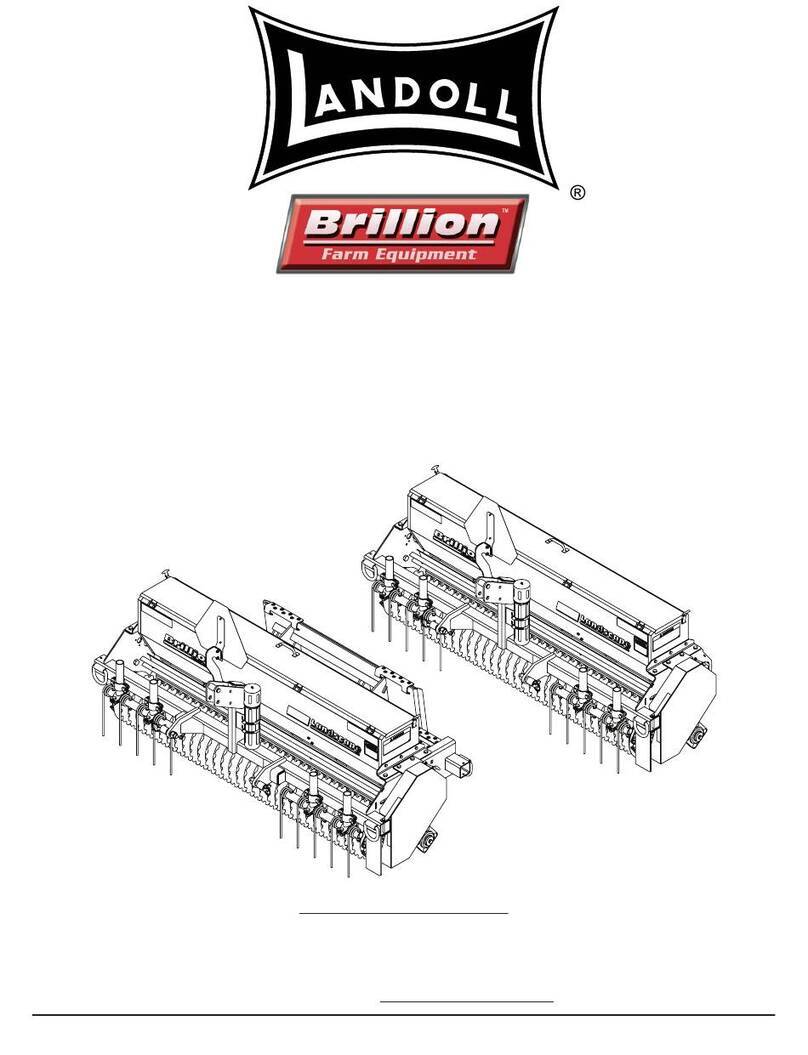
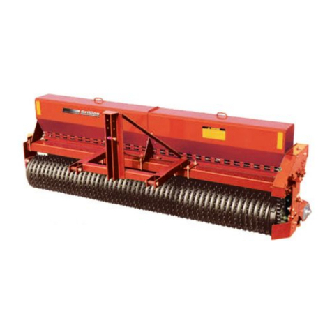
Landoll Brillion LSP5 User manual


i
Table of Contents
1 Safety Information
Introduction . . . . . . . . . . . . . . . . . . . . . . . . . . . . . . . . . . . . . . . . . . . . . . . . . . . . . . . . . . . . . . . . . . 1-1
Description of Unit . . . . . . . . . . . . . . . . . . . . . . . . . . . . . . . . . . . . . . . . . . . . . . . . . . . . . . . . . . . . . 1-1
Using this Manual . . . . . . . . . . . . . . . . . . . . . . . . . . . . . . . . . . . . . . . . . . . . . . . . . . . . . . . . . . . . . 1-1
Owner Assistance . . . . . . . . . . . . . . . . . . . . . . . . . . . . . . . . . . . . . . . . . . . . . . . . . . . . . . . . . . . . . 1-1
Warranty Registration . . . . . . . . . . . . . . . . . . . . . . . . . . . . . . . . . . . . . . . . . . . . . . . . . . . . . . . . . . 1-1
Understanding Safety Statements . . . . . . . . . . . . . . . . . . . . . . . . . . . . . . . . . . . . . . . . . . . . . . . . 1-2
Transporting Safety . . . . . . . . . . . . . . . . . . . . . . . . . . . . . . . . . . . . . . . . . . . . . . . . . . . . . . . . . . . . 1-3
Attaching, Detaching, Storage . . . . . . . . . . . . . . . . . . . . . . . . . . . . . . . . . . . . . . . . . . . . . . . . . . . 1-3
Maintenance Safety . . . . . . . . . . . . . . . . . . . . . . . . . . . . . . . . . . . . . . . . . . . . . . . . . . . . . . . . . . . . 1-3
Protective Equipment . . . . . . . . . . . . . . . . . . . . . . . . . . . . . . . . . . . . . . . . . . . . . . . . . . . . . . . . . . 1-3
Chemical Safety . . . . . . . . . . . . . . . . . . . . . . . . . . . . . . . . . . . . . . . . . . . . . . . . . . . . . . . . . . . . . . . 1-3
Prepare for Emergencies . . . . . . . . . . . . . . . . . . . . . . . . . . . . . . . . . . . . . . . . . . . . . . . . . . . . . . . . 1-3
Safety Decals . . . . . . . . . . . . . . . . . . . . . . . . . . . . . . . . . . . . . . . . . . . . . . . . . . . . . . . . . . . . . . . . . 1-4
2 Operation
Landscape Seeder Operation . . . . . . . . . . . . . . . . . . . . . . . . . . . . . . . . . . . . . . . . . . . . . . . . . . . . 2-1
Attaching to a Tractor . . . . . . . . . . . . . . . . . . . . . . . . . . . . . . . . . . . . . . . . . . . . . . . . . . . . . . 2-2
Seed Rate Adjustment-Adjusting the Box Slide . . . . . . . . . . . . . . . . . . . . . . . . . . . . . . . . . . . . . 2-3
Calibration of the Seed Box . . . . . . . . . . . . . . . . . . . . . . . . . . . . . . . . . . . . . . . . . . . . . . . . . . . . . 2-4
Planting Rates for Seed Box . . . . . . . . . . . . . . . . . . . . . . . . . . . . . . . . . . . . . . . . . . . . . . . . . . . . . 2-4
Doubling the Seed Rate . . . . . . . . . . . . . . . . . . . . . . . . . . . . . . . . . . . . . . . . . . . . . . . . . . . . . . . . . 2-5
Acre Meter (Optional) . . . . . . . . . . . . . . . . . . . . . . . . . . . . . . . . . . . . . . . . . . . . . . . . . . . . . . . . . . . 2-6
Settings for Loup Acre Meters After 05/15/2012 . . . . . . . . . . . . . . . . . . . . . . . . . . . . . . . . . . . . . 2-6
Field Acres . . . . . . . . . . . . . . . . . . . . . . . . . . . . . . . . . . . . . . . . . . . . . . . . . . . . . . . . . . . . . . 2-6
Total Acres . . . . . . . . . . . . . . . . . . . . . . . . . . . . . . . . . . . . . . . . . . . . . . . . . . . . . . . . . . . . . . 2-6
Pulses Per 400 Feet . . . . . . . . . . . . . . . . . . . . . . . . . . . . . . . . . . . . . . . . . . . . . . . . . . . . . . .2-6
Width . . . . . . . . . . . . . . . . . . . . . . . . . . . . . . . . . . . . . . . . . . . . . . . . . . . . . . . . . . . . . . . . . . . 2-6
Password . . . . . . . . . . . . . . . . . . . . . . . . . . . . . . . . . . . . . . . . . . . . . . . . . . . . . . . . . . . . . . . . 2-6
Changing The Password . . . . . . . . . . . . . . . . . . . . . . . . . . . . . . . . . . . . . . . . . . . . . . . . . . . . 2-7
Quick-start Settings for Loup Acre Meters Prior to 05/15/2012 . . . . . . . . . . . . . . . . . . . . . . . . . 2-7
To Program Meter . . . . . . . . . . . . . . . . . . . . . . . . . . . . . . . . . . . . . . . . . . . . . . . . . . . . . . . . .2-7
To Enter Password . . . . . . . . . . . . . . . . . . . . . . . . . . . . . . . . . . . . . . . . . . . . . . . . . . . . . . . .2-7
To Disable Password . . . . . . . . . . . . . . . . . . . . . . . . . . . . . . . . . . . . . . . . . . . . . . . . . . . . . . 2-7
Battery Replacement . . . . . . . . . . . . . . . . . . . . . . . . . . . . . . . . . . . . . . . . . . . . . . . . . . . . . . .2-7
Adjustment of Wheel Track Remover . . . . . . . . . . . . . . . . . . . . . . . . . . . . . . . . . . . . . . . . . . . . 2-10

ii
3 Assembly Of Optional Equipment
Agitator Blades (Optional Cage or Brushes) . . . . . . . . . . . . . . . . . . . . . . . . . . . . . . . . . . . . . . . . 3-1
Changing Agitator Kits . . . . . . . . . . . . . . . . . . . . . . . . . . . . . . . . . . . . . . . . . . . . . . . . . . . . . . . . . 3-1
Lift Sling Kit (Optional) . . . . . . . . . . . . . . . . . . . . . . . . . . . . . . . . . . . . . . . . . . . . . . . . . . . . . . . . . 3-3
Acre Meter Kit 6K036 Installation . . . . . . . . . . . . . . . . . . . . . . . . . . . . . . . . . . . . . . . . . . . . . . . . . 3-4
4 Maintenance
General Torque Specifications . . . . . . . . . . . . . . . . . . . . . . . . . . . . . . . . . . . . . . . . . . . . . . . . . . . 4-1
Fasteners . . . . . . . . . . . . . . . . . . . . . . . . . . . . . . . . . . . . . . . . . . . . . . . . . . . . . . . . . . . . . . . . . . . . . 4-2
Acre Meter . . . . . . . . . . . . . . . . . . . . . . . . . . . . . . . . . . . . . . . . . . . . . . . . . . . . . . . . . . . . . . . . . . . . 4-2
Lubrication . . . . . . . . . . . . . . . . . . . . . . . . . . . . . . . . . . . . . . . . . . . . . . . . . . . . . . . . . . . . . . . . . . . 4-2
Chain Tension . . . . . . . . . . . . . . . . . . . . . . . . . . . . . . . . . . . . . . . . . . . . . . . . . . . . . . . . . . . . . . . . . 4-3
Roller Wheels . . . . . . . . . . . . . . . . . . . . . . . . . . . . . . . . . . . . . . . . . . . . . . . . . . . . . . . . . . . . . . . . . 4-3
Maintenance Chart . . . . . . . . . . . . . . . . . . . . . . . . . . . . . . . . . . . . . . . . . . . . . . . . . . . . . . . . . . . . . 4-4
5 Specifications

1-1
Chapter 1
Safety Information
Introduction
The implement described in this manual has been
designed with care and built by skilled workers using
quality materials and processes. Proper assembly,
maintenance and safe operation will allow this machine
to provide you with satisfactory use for seasons to come.
DANGER
Description of Unit
The LSP Landscape Seeder is the latest addition to the
Brillion lineup of landscape turfmaker seeders. With it's
single landscape style box that is equipped with the
polyethylene blade type agitator, this unit can handle
most turf seeds with ease. Built on a structural tube
mainframe, this seeder provides increased seed box
capacity and a simplified roller chain drive system. The
seeder roller assemblies have greaseable, flange style,
self aligning bearings. The integral Cat. I 3-point hitch
provides for a close coupled unit that compliments the
new generation of compact tractors very well.
The Brillion LSS6 Skid Steer Landscape Seeder, new to
the Landscape Seeder lineup, is a bi-directional seeder
with a three point hitch that can be attached to the front
or rear of the seeder frame. A skid steer quick-attach
mounting plate is standard equipment. Depending on the
choice of mounting, the seeder can be either pushed or
pulled by the skid steer. In addition, the seeder will also
mount to tractors with a standard Cat. 1 three point hitch.
The machine shown in the following illustrations may not
directly match with your unit. Your assembled machine,
however, is similar for all models. Additional parts
identification and location can be obtained by reviewing
the parts catalog 7K457.
Using this Manual
This manual will familiarize you with safety, assembly,
operation, adjustment, and maintenance. Read this
manual and follow the recommendations to help ensure
safe and efficient operation.
• The information in this manual is current at time of
printing. Some parts may change to assure top
performance.
• Location reference: Right and Left designations in this
manual are determined by facing the direction the
machine will travel during field operation, unless
otherwise stated.
Owner Assistance
If customer service or repairs are needed, contact your
Brillion dealer. They have trained personnel, parts and
service equipment specially designed for Brillion
products. Your machine’s parts should only be replaced
with Brillion parts. Have the Serial Number and complete
Model Number available when ordering parts from your
Brillion dealer. See Figure 1-1.
Warranty Registration
Brillion Farm Equipment, by Landoll, shall have no
warranty obligation unless each product is registered,
within 10 days of retail purchase, using the Landoll
Corporation Ag Products on-line registration process.
Please refer to the Ag Products Policy and Procedures
Manual, accessible at www.landoll.com for step by step
instructions regarding product registration.
Enter your product information below for quick reference.
MODEL NUMBER
SERIAL NUMBER
DATE OF PURCHASE
Read this entire manual before attempting to
assemble, adjust or operate this machine.
Failure to comply with this warning can result in
personal injury or death, damage to the machine
or its components and inferior operation.

1-2 7K458
SAFETY INFORMATION
Figure 1-1: ID Plate
Federal law requires that you explain the safety and
operating instructions furnished with this machine to all
operators before they are allowed to operate the
machine. These instructions must be repeated to the
operators at the beginning of each season. Be sure to
observe and follow the instructions for the safety of
anyone operating or near the machine.
NOTE
Investigation has shown that nearly 1/3 of all farm
accidents are caused by careless use of machinery.
Insist that all people working with you or for you abide by
all safety instructions.
Understanding Safety
Statements
NOTICE
CAUTION
WARNING
DANGER
NOTE
You should read and understand the information
contained in this manual and on the machine decals
before you attempt to operate or maintain this equipment.
•Examine safety decals and be sure you have the
correct safety decals for the machine. See Safety
Sign and Locations in Safety Section for decal
locations, See Figures 1-2 and 1-3 for reference.
Order replacement decals through your Brillion
dealer.
• Keep these signs clean so they can be observed
readily. It is important to keep these decals cleaned
more frequently than the machine. Wash with soap
and water or a cleaning solution as required.
• Replace decals that become damaged or lost. Also, be
sure that any new machine components installed
during repair include decals which are assigned to
them by the manufacturer.
• When applying decals to the machine, be sure to
clean the surface to remove any dirt or residue. Where
possible, sign placement should protect the sign from
abrasion, damage, or obstruction from mud, dirt, oil
etc.
Special notice - read and thoroughly understand.
Proceed with caution. Failure to heed caution
may cause injury to person or damage product.
Proceed with caution. Failure to heed warning will
cause injury to person or damage product.
Proceed with extreme caution. Failure to heed
notice will cause injury or death to person and/or
damage product.

SAFETY INFORMATION
1-3
DANGER
Transporting Safety
IMPORTANT
It is the responsibility of the owner/operator to
comply with all state and local laws.
• When transporting the machine on a road or highway,
use adequate warning symbols, reflectors, lights and
slow moving vehicle sign as required. Slow moving
tractors and towed implements can create a hazard
when driven on public roads. They are difficult to see,
especially at night.
• Do not tow an implement that, when fully loaded,
weighs more than 1.5 times the weight of the towing
vehicle.
• Carry reflectors or flags to mark the tractor and
implement in case of breakdown on the road.
• Do not transport at speeds over 20 MPH under good
conditions. Never travel at a speed which does not
allow adequate control of steering and stopping.
Reduce speed if towed load is not equipped with
brakes.
• Avoid sudden stops or turns because the weight of the
machine may cause the operator to lose control of the
tractor. Use a tractor heavier than the machine.
• Use caution when towing behind articulated steering
tractors; fast or sharp turns may cause the machine to
shift sideways.
• Keep clear of overhead power lines and other
obstructions when transporting. Know transport height
and width of your machine.
Attaching, Detaching, Storage
• Do not stand between the tractor and implement
when attaching or detaching implement unless both
are prevented from moving.
Maintenance Safety
• Block the machine so it will not roll when working on or
under it to prevent injury in case of hydraulic failure or
inadvertent lowering by another person.
• Do not make adjustments or lubricate machine while it
is in motion.
• Make sure all moving parts have stopped and all
system pressure is relieved.
• Keep all guards in place. Replace any that become
damaged.
• Understand the procedure before doing the work. Use
proper tools and equipment.
NOTES
On most tractors relieving hydraulic pressure can be
accomplished by operating valves after the engine is
stopped. Also, the machine should be lowered to ground
so that the shanks are taking the load.
Wear protective gloves and safety glasses or goggles
when working with hydraulic systems.
Protective Equipment
• Wear protective clothing and equipment.
• Wear clothing and equipment appropriate for the job.
Avoid loose fitting clothing.
• Because prolonged exposure to loud noise can cause
hearing impairment or hearing loss, wear suitable
hearing protection, such as earmuffs or earplugs.
Chemical Safety
• Agricultural chemicals can be dangerous. Improper
use can seriously injure persons, animals, plants, soil
and property.
• Read chemical manufactures instructions and store or
dispose of unused chemicals as specified.
• Handle chemicals with care and avoid inhaling smoke
from any type of chemical fire.
• Store or dispose of unused chemicals as specified by
the chemical manufacturer.
Prepare for Emergencies
• Keep a First Aid Kit and Fire Extinguisher handy.
• Keep emergency numbers for doctor, ambulance,
hospital and fire department near phone.
• Keep Riders Off of Machinery
Do not allow anyone to ride on tractor or
machine. Riders could be struck by foreign
objects or thrown from the machine.
• Never allow children to operate equipment.
• Keep bystanders away from machine during
operation.


1-4 7K458
SAFETY INFORMATION
Safety Decals
Figure 1-2: Decals
7
3
2
1
4
6
5
DISENGAGE CLUTCH (IF SO
EQUIPPED) OR RAISE SEEDER
BEFORE BACKING UP. FAILURE
TO DO SO WILL DAMAGE
BRUSH AGITATORS.
IMPORTANT
5D505
PARKINGPARKING
PARKINGPARKING
PARKING
PINPIN
PINPIN
PIN
9J301
WARNING
MOVING PART HAZARD
2K123
CAUTION
1. DO NOT LUBRICATE, ADJUST OR REPAIR WHEN MACHINE IS IN MOTION.
2. DO NOT TOW OR TRANSPORT FASTER THAN 15 MILES PER HOUR.
3. DO NOT RIDE OR ALLOW OTHERS TO RIDE ON THE MACHINE.
4. BLOCK UP ALL HYDRAULICALLY OR MECHANICALLY RAISED COMPONENTS TO PREVENT
UNINTENDED LOWERING OR LOWER THE MACHINE TO THE GROUND TO MAKE ADJUSTMENT
OR REPAIRS OR WHEN NOT IN USE.
5. KEEP ALL PERSONS AWAY FROM MACHINE DURING HITCHING AND OPERATING.
6. SLOW DOWN BEFORE MAKING SHARP TURNS OR USING THE BRAKE.
DRIVE SLOWLY OVER ROUGH GROUND, SIDE HILLS, AND AROUND CURVES TO AVOID TIPPING.
7. COMPLY WITH ALL LAWS WHEN TRANSPORTING THE MACHINE ON PUBLIC ROADWAYS.
8. INSTRUCT ALL OPERATORS IN THE SAFE OPERATION OF THE MACHINE.
REVIEW THE OPERATOR’S MANUAL FOR CORRECT PROCEDURES.
9. BLOCK IMPLEMENT TO PREVENT MOVEMENT WHEN UNHITCHED FROM TRACTOR.
10. KEEP ALL GUARDS AND SHIELDS IN PLACE WHILE MACHINE OR PARTS ARE IN MOTION.
8J310
CAUTION
BE SURE TO ENGAGE
PARKING PIN ON LEFT END OF
FRAME BEFORE UNHITCHING
TRACTOR. OTHERWISE
FRAME WILL TIP BACKWARDS
ABOUT FRONT AXLE 9J302
11
8
7K341
Landscape 6
10 9

SAFETY INFORMATION
1-5
Figure 1-3: Decal Locations

1-6 7K458
SAFETY INFORMATION
Table provided for general use.
NOTES:

2-1
Chapter 2
Operation
Landscape Seeder Operation
The Brillion Landscaper Seeder is fully assembled from
the factory. This section refers to how to successfully
operate your machine. Refer to the parts catalog for
complete part breakdowns. Be sure to read and
understand the Safety Procedures and Cautions starting
on page 1-2.
"Left" and "Right" designation is determined by facing the
direction the machine will travel during field operation,
unless otherwise stated.
• If pre-assembled parts or fasteners are temporarily
removed, remember where they go. It is best to keep
parts separated.
• Check that all working parts move freely, bolts are tight
and cotter pins are spread.
• Refer to the Torque Chart in Chapter 4 for proper bolt
torque values.
Note the different torque requirement for bolts with lock
nuts. Refer to Torque Chart in Chapter 4.
DANGER
WARNING
Figure 2-1: Landscape Grass Seeder Concept
Always be sure the front of the tractor has
enough weight to maintain control when the
machine is raised.
When transporting on roadways, obey all
applicable laws and regulations.
Do not transport at speeds over 20 mph under
good conditions. Never travel at a speed which
does not allow adequate control of steering or
stopping.
Avoid sudden stops or turns because the weight
of the machine may cause the operator to lose
control of the tractor.
Make sure your slow moving vehicle sign is clean
and visible.

2-2 7K458
OPERATION
Attaching to a Tractor
When hooking up seeders:
• Attach tractor.
• Remove klik pin, pull parking pin into outer position,
• Replace klik pin.
When unhooking seeder:
• Remove klik pin, push in parking pin,
• Replace klik pin.
• Disconnect tractor.
On LSS6, skid steer models, there is a parking pin
located on each side of the frame. In addition, a quick
attach frame attaches to the rear frame tube of the
seeder by means of two pins and klik pins. See
Figure 2-2.
Figure 2-2: Attaching to a Tractor
Parking
Pin
Klik
Pin
Use this hole when
(Use this hole when
connected to tractor)
Parking Pin
(each side)
Quick
Attach
Frame
Pin,
(2) Klik pins
Disconnected from the tractor

OPERATION
2-3
Seed Rate Adjustment-Adjusting
the Box Slide
When properly adjusted, with the control handle set at
“6”. The holes in the slide should line up with the holes in
the box, See Figure 2-3. To make an adjustment, loosen
the control handle on the box, move the slide until the
holes line up. When the handle is moved to “0” the holes
in the box should be completely covered. See Figure 2-4.
If the holes are not covered, loosen the three bolts
holding the seedmeter casting and shift it slightly so that
the “0” mark is farther from the control handle. Retighten
the bolts. Move control handle to “0”. Holes in the box
should then be completely covered. See Figure 2-5.
Figure 2-3: Control Handle at “6”
Figure 2-4: Control Handle at “0”
Figure 2-5: Seedmeter Casting Bolts
If the holes are not covered
when set at 0, loosen these
three bolts holding the
seedmeter casting and shift
it slightly. Retigthen the bolts.

2-4 7K458
OPERATION
Calibration of the Seed Box
Seed box may be calibrated for unlisted seeds as follows:
See Figure 2-6.
1. Raise machine and lock in transport position.
2. Place a tarp under machine to collect seed.
3. Turn the 3/4 Hexagon Sprocket Shaft
counterclockwise (CCW).
279 Revolutions for 5 Foot Seeders.
232 Revolutions for 6 Foot Seeders.
4. Weigh seed and multiply by 10 for 13 Tooth Driver
Sprocket and by 20 for 26 Tooth Driver Sprocket to
get approximate planting rate in pounds per acre.
Figure 2-6: Seed Box Calibration
Planting Rates for Seed Box
1. See Figure 2-7. Rates are based upon using 13
Tooth Driver Sprocket. Double these values when
using 26 Tooth Driver Sprocket.
2. Rates are intended as a guide only. Variation in size
and cleanliness will affect rates.
Check acreage & lbs. of seed used for best results.
Figure 2-7: Seed Rate Chart 13 Tooth Driver
7227+
'5,9(1
7227+
,'/(5
7227+
25
7227+
'5,9(5
7227+
+(;
3281'63(5$&5(3281'63(5 64 )7
,1',&$725 6(77,1*6
6(('(5(48,33(' :,7+%586+$*,7$7256
%HQW *UDVV +LJKODQG
%OXHJUDVV .HQWXFN\
%OXHJUDVV 0HULRQ
)HVFXH &UHHSLQJ 5HG
2DWV
5\HJUDVV $QQXDO
5\HJUDVV 3HUHQQLDO
:KHDW *UDVV 7DOO
6(('(5(48,33(' :,7+ %/$'( $*,7$7256
%HQW *UDVV +LJKODQG
%OXHJUDVV .HQWXFN\
%OXHJUDVV 0HULRQ
)HVFXH &UHHSLQJ 5HG
2DWV
5\HJUDVV $QQXDO
5\HJUDVV 3HUHQQLDO
:KHDW *UDVV 7DOO
-PX HFSNJOBUJPO NBZPDDVS EVF UP TIBMMPX TFFEJOHEFQUI GPS UIJT TFFE
1RW5HFRPPHQGHG
1RW5HFRPPHQGHG
1RW5HFRPPHQGHG
1RW5HFRPPHQGHG

OPERATION
2-5
Doubling the Seed Rate
Seed rates can be doubled by using the 26-tooth
sprocket and extra chain links included with the seeder.
See Figure 2-8.
Procedure is as follows:
1. Loosen drive chain.
Figure 2-8: Speed Up Kit
2. Open chain at connector.
3. Remove 1/4” roll pin in 13- tooth sprocket and 3/4”
nut on 26-tooth sprocket. See Figure 2-9.
4. Exchange sprockets to new positions and replace roll
pin and nut.
5. Add extra chain links as provided with this seeder.
Adjust chain tension as shown on page 4-3.
Figure 2-9: Doubling the Seed Rate
'ULYH&KDLQ6HW)RU
7RRWK6HHG5DWH
5HPRYH
7RRWK
6SURFNHW
$GG([WUD
/LQNV
5HPRYH´
5ROO3LQ 'ULYH&KDLQ6HW)RU
7RRWK6HHG5DWH
5HSODFH
´5ROO3LQ
6WRUH
7RRWK
6SURFNHW
´1XW
´1XW
´1XW

2-6 7K458
OPERATION
Acre Meter (Optional)
Settings for Loup Acre Meters
After 05/15/2012
The battery operated acre counter operates in one of two
modes. In sleep mode, the display is blank, and the
counter is accumulating acres. Sleep mode will be
entered if a button is not pressed for 20 seconds. In entry
mode, the display is on, and the operator can enter
values. To get into entry mode, press the */FUNC
button. If you continue to press the */FUNC button, the
acre counter will cycle through the functions that it can
perform. The LEDs above the display indicate which
function is selected.
The available functions are:
Field Acres, Total Acres, Pulses per 400 ft, Width,
Password and Low Battery
Field Acres
Press the */FUNC button until the “FIELD” LED is lit.
The digits indicate the acres covered since the field acre
counter was cleared.
To clear the field acre count, press the UP and DOWN
buttons simultaneously for two seconds. If a password
has been entered, you will not be able to clear the total
acre count. Field acres will count in tenths of an acre up
to 9999.9 acres.
Total Acres
Press the */FUNC button until the “FIELD” and “TOTAL”
LEDs are lit. The digits indicate the acres covered since
the total acre counter was cleared.
To clear the total acre count, press and hold the UP and
DOWN buttons for two seconds. If a password has been
entered, you will not be able to clear the total acre count.
Total acres will count from.1 to 99999 acres.
Pulses Per 400 Feet
Press the */FUNC button until the “PULSES” LED is lit.
The number in the display indicates how many pulses are
generated for every 400 feet driven. There are two
methods to enter the pulses per 400 feet:
If you know the number, select it using the UP and
DOWN buttons. When you press the */FUNC button,
the Acre Counter will accept the number in the display as
the new pulses per 400 feet. See Table 2-1.
If you do not know the pulses per mile, press and hold the
UP and DOWN buttons until the “0000” appears in the
display. The “PULSES” LED will blink. The acre counter
is now counting shaft rotations. Enter the cab and drive
400 feet. Press the */FUNC button to wake up the acre
counter. The “PULSES” LED will again blink. The number
displayed is the pulses per 400 feet. Press the */FUNC
button to accept the setting. The “PULSES” LED will stop
blinking and remain on.
If a password is set, you will not be able to adjust the
pulses per mile.
Width
Press the */FUNC button until the “WIDTH” LED is lit.
The number displayed is the length of your implement in
feet.
To adjust the width, press the UP and DOWN buttons. If a
password has been entered, you will not be able to adjust
the width.
The length can be adjusted from .1 to 99.9 feet, in tenths
of a foot.
Password
The password function allows you to protect the total acre
count, pulses per 400 feet, and width settings with a
password. This stops anyone from accidentally changing
those settings. When the acre counter is shipped, the
password is disabled. You can modify the pulses per 400
feet and implement width at any time.
Press the */FUNC button until the “PASS” LED is lit. The
digits will display the word “Ent” or “dIS”.
If the display shows “dIS”: The password is disabled. The
total acre count, pulses/400 ft, width, and password
settings can be adjusted using the UP and DOWN
buttons. The password can also be changed using the
UP and DOWN buttons.
If the display shows “Ent”: You must enter your password
using the UP and DOWN buttons. When your password
is displayed, press the */FUNC button to test the
password. If the password is correct, you will be able to
change the acre counter settings. The password will be
viewable until the acre counter powers down. When the
acre counter is powered up again, you will have to
re-enter the password to change settings.
If the password is not correct, you will not be able to
change the acre counter settings. When the “PASS ”
function is selected again, “Ent” will appear in the display.

OPERATION
2-7
Changing The Password
Select a new password using the UP and DOWN buttons.
Press the */FUNC button until the word “SEt” appears in
the display. Release the */FUNC button. The number in
the display is your new pass code. Make sure you record
this number. Press and hold the */FUNC button until the
word “dIS” appears in the display.
If the password is forgotten, it can be disabled by
removing the batteries. The password is intended for
rental units. It is recommended that a seal be affixed to
the rear plate of the acre counter to determine if the
settings have been tampered with.
Quick-start Settings for Loup
Acre Meters Prior to 05/15/2012
• When the meter is set to “count” mode in pulses screen,
meter will register only magnetic wheel revolutions.
• The meter must be in sleep mode (blank screen) to
calculate acres or to count pulses.
• The count screen must have a value other than zero
(0000) to scroll to other modes or screens.
• To reset the FIELD ACRES screen to zero (0000), press
the up and down buttons simultaneously.
To Program Meter
1. Press the function button to scroll to pulses screen.
2. Enter the number of pulses using the up or down
buttons for the model listed in the chart. See
Ta bl e 2 - 2 .
3. Press the function button to set the pulses. (If screen
goes blank before you press the function button,
repeat steps 1 and 2).
4. Press the function button to scroll to the width
screen.
5. Enter the width of seeder using the up or down
buttons for the model listed in the chart. See
Ta bl e 2 - 2 .
6. Press the function button to set the width. (If screen
goes blank before you press the function button,
repeat steps 4 and 5).
7. Press the function to scroll through the screens to
check that the correct pulses and width have been
entered.
To Enter Password
1. Press the function button to scroll to password
screen.
2. Pick a numeric password and enter it by using the up
or down buttons, until your password is displayed.
3. Press the function button to set password; screen will
show “(set)”. Record number - it is required if you
decide to disable password.
4. Let screen go blank - password is now entered.
5. Press the function button to scroll to the password
screen it will show (ent). If the screen does not show
(ent), repeat steps 2, 3 and 4.
To Disable Password
1. Press the function button to scroll to the password
screen it will show (ent).
2. Use up or down button to enter password (number).
3. Press the function button to scroll around to pass
screen again. Number entered in step 2 will appear.
4. Press up or down button to enter 0.
5. Press the function button; (dis) will appear. Password
is now disabled.
Battery Replacement
The battery operated acre counter uses 3 AA batteries.
The batteries should last between 5 and 10 years. The
acre counter will last much longer than that. Eventually,
you will have to replace the batteries. The “BATT” LED
will light when the batteries require replacement. Remove
the acre counter from the implement and undo the 4
screws on the back of the case. This will separate the
housing from the rear plate. Replace the batteries with 3
high quality AA alkaline batteries.
This unit is dust and splash resistant, under no
circumstances should this unit be submerged in any
conductive, corrosive, or flammable liquid.

2-8 7K458
OPERATION
Table 2-1: Acre Meter Settings (After to 05/15/2012)
MODEL PULSES WIDTH
SSP T604 22 5.0
SSP4 SS4 44 4.0
SSP5 SS5 44 5.0
SSP6 SS6 58 6.0
SSP8 SS8 58 8.0
SSP10 SS10 58 10.0
SSP12 SS12 58 12.0
SSP108 SS108 58 8.0
SSP110 SS110 58 10.0
SSP112 SS112 58 12.0
SSP208 SSP2081 SS208 SS2081 58 8.0
SSP210 SSP2101 SS210 SS2101 58 10.0
SSP212 SSP2121 SS212 SS2121 58 12.0
SSP308 SS308 29 8.0
SSP310 SS310 29 10.0
SSP312 SS312 29 12.0
SLP8 SL8 314 8.0
SLP10 SL10 314 10.0
SLP12 SL12 314 12.0
SLP204 SLP2041 128 4.0
SLP206 SLP2061 128 6.0
SLP304 SLP3041 64 4.0
SLP306 SLP3061 64 6.0
LSP5 128 5.0
LSP6 128 6.0
LSS6 128 6.0
SLP208 SLP2081 SL208 SL2081 116 8.0
SLP210 SLP2010 SL210 SL2101 116 10.0
SLP212 SLP2012 SL212 SL2121 116 12.0
SLP308 SLP3081 SL308 SL3081 58 8.0
SLP310 SLP3101 SL310 SL3101 58 10.0
SLP312 SLP3121 SL312 SL3121 58 12.0
BOS4F1 BOS4S1 BOS6F1 BOS6S1 45 4.0
BOSB4F1 BOSB4S12 BOSB6F1 BOSB6S1 45 6.0
BPS6 BPSB6 51 6.0
GLP643 SSLP643 69 5.3

OPERATION
2-9
Table 2-2: Acre Meter Settings (Prior to 05/15/2012)
MODEL Pulses Width
SSP T604 293 5
SSP4 SS4 578 4
SSP5 578 5
SSP6 SS6 578 6
SSP8 SS8 764 8
SSP10 SS10 764 10
SSP12 SS12 764 12
SSP108 SS108 760 8
SSP110 SS110 760 10
SSP112 SS112 760 12
SSP208 SSP2081 SS208 SS2081 764 8
SSP210 SSP2101 SS210 SS2101 764 10
SSP212 SSP2121 SS212 SS2121 764 12
SSP308 SS308 382 8
SSP310 SS310 382 10
SSP312 SS312 382 12
SLP8 SL8 4147 8
SLP10 SL10 4147 10
SLP12 SL12 4147 12
SLP204 SLP2041 1690 4
SLP206 SLP2061 1690 6
SLP304 SLP3041 845 4
SLP306 SLP3061 845 6
LSP5 1690 5
LSP6 1690 6
LSS6 1690 6
SLP208 SLP2081 SL208 SL2081 1528 8
SLP210 SLP2101 SL210 SL2101 1528 10
SLP212 SLP2121 SL212 SL2121 1528 12
SLP308 SLP3081 SL308 SL3081 764 8
SLP310 SLP3101 SL310 SL3101 764 10
SLP312 SLP3121 SL312 SL3121 764 12
BOS4F1 BOS4S1 BOS6F1 BOS6S1 600 4
BOSB4F1 BOSB4S1 BOSB6F1 BOSB6S1 600 6
BPS6 BPSB6 679 6
GLP643 SSLP643 917 5

2-10 7K458
OPERATION
Adjustment of Wheel Track
Remover
The depth of the wheel track removers can be adjusted
as shown. See Figure 2-10. Loosen the 1/2-13 x 1-1/4
bolts and nuts that secure the clamps to the coil tine
supports. Adjust the supports up or down to the desired
depth and then retighten the nuts on the bolts. Do this for
each pipe and tine assembly.
Figure 2-10: Wheel Track Remover
%ROW
[´
1XW´
Other manuals for Brillion LSP5
2
This manual suits for next models
2
Table of contents
Other Landoll Seeder manuals

Landoll
Landoll Brillion SSP4 User manual

Landoll
Landoll Brillion SSB User manual

Landoll
Landoll Brillion LSP5 User manual

Landoll
Landoll BRILLION SL Series User manual

Landoll
Landoll Brillion 4630-36 Series User manual

Landoll
Landoll Brillion Turfmaker II Series User manual

Landoll
Landoll Brillion Turfmaker III Series User manual

Landoll
Landoll Brillion SS16 User manual

Landoll
Landoll SSB-8 User manual