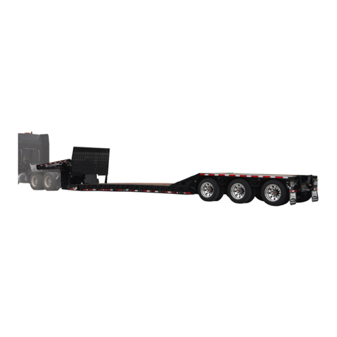
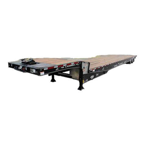
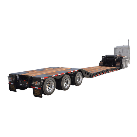
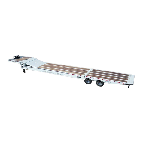
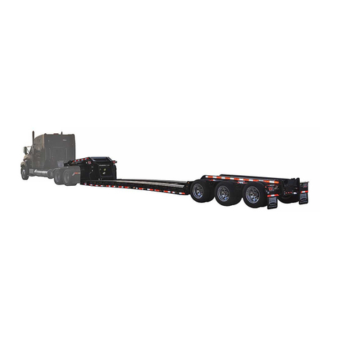
Landoll 318C User manual

MODELS 318C
BOEING TRAILER
OPERATOR’S MANUAL
Landoll Trailer Operations
4G75021-P0400
1900 North Street
Marysville, KS 66508
(785)562-5381
F-414-0106 01/06

LANDOLL CORPORATION
TRAILER FIVE YEAR LIMITED WARRANTY POLICY
Landoll Corporation warrants each new Trailer structure manufactured by Landoll Corporation to be free from defects in materials and
workmanship. This limited warranty is subject to specific exclusions and does not apply to any trailer which has been: 1) subjected to
or operated with loads which, at any time, have exceeded the trailer’s rated capacity or design limits: 2) repaired or altered outside our
factory in any way so as, in our judgment, to affect its stability or reliability: 3) subject to misuse, negligence, accident, or has been op-
erated in a manner expressly prohibited in the instructions; or not operated in accordance with practices approved by Landoll Corpora-
tion. Trailer structure shall be considered the framework of the trailer (mainframe and/or rear frame weldment, gooseneck weldment
and undercarriage weldment) which is fabricated by Landoll Corporation.
The sole obligation of Landoll Corporation under this warranty shall be limited to repairing or replacing, at its option, in accordance with
the schedule below, a defective new Trailer structure which shall be identified to Landoll Corporation by way of a Landoll Corporation
e-mail Warranty Claim Form within five (5) years from the date of registration of Trailer. Warranty, expressed or implied, will be denied
on any Trailer not properly registered with the Landoll Corporation Warranty Department within ten (10) days of the first retail sale.
Landoll Corporation Warranty Staff will identify components listed on a Warranty Claim required to be returned for further analysis. All
parts returned to Landoll Corporation must be shipped with a Return Materials Authorization (RMA) provided by the Landoll Corpora-
tion Warranty Staff. Defective components must returned by the purchaser to Landoll Corporation with transportation and freight
charges prepaid within fifteen (15) days after receipt of the RMA. The examination conducted by Landoll Corporation of returned parts
shall disclose to its satisfaction the extent the component may be detective.
All labor and parts warranty MUST be authorized by Landoll Corporation Warranty Staff. Failure to do so will result in no warranty
payment of any kind. Labor will be reimbursed in accordance with published shop rates pre-approved by the Landoll Corporation War-
ranty Staff. Time authorized for specific work will be limited, where appropriate, to the hours listed in the Landoll Corporation author-
ized Flat Rate Schedule.
THIS WARRANTY IS EXPRESSLY IN LIEU OF ALL OTHER WARRANTIES OF MATERIAL, WORKMANSHIP, DESIGN, APPLICA-
TION OR OTHERWISE WITH RESPECT TO ANY EQUIPMENT, WHETHER EXPRESS OR IMIPLIED, INCLUDING WARRANTIES
OF MERCHANTABILITY AND FITNESS FOR A PARTICULAR PURPOSE, AND OF ALL OTHER OBLIGATIONS OR LIABILITIES
ON THE PART OF LANDOLL COPRPORATION.
New Trailer Structure Schedule: Landoll Corporation shall bear that portion of the cost of repairing or replacing the new structure of
the Trailer found to be defective within a sixty (60) month warranty period prorated on the following basis:
One (1) Year - 100% Three (3) Years - 70% Five (5) Years - 50%
Two (2) Years - 80% Four (4) Years - 60%
All Bottom Dump and Industrial and Utility Tag Trailers are exempt from the 5 year structural warranty and carry a 12 month structural
warranty, due to the rugged and abusive off road use in which these off road units typically operate, and are subject to the Component
Schedule below .
Component Schedule: Components manufactured by Landoll Corporation (other than the Structure) and Components supplied by
other manufacturers shall be warranted under the following schedule:
I. Axles, Suspensions, Landing Gear, Wheels, Rims, Hubs, Rollers and Cam Followers,
Hydraulic Valve Body and other Landoll Corporation Components.
Coverage: 1 year 100%, Over 1 year 0%
II. Air Lines, Springs, Air Bags, Leveling Valves, Bearings, Brake Valves, Paint, Oil Seals, Engines,
Brake Drums, Shock Absorbers, Electrical, Cylinders, Wear Plates, Hydraulic Hoses & Connections
Coverage: 1 - 6 months 100% Over 6 months 0%
III. Tires and Tubes Coverage: Warranty claims must be made directly to the tire dealers.
IV. Wood Components Coverage: 0%
This warranty does not expand, enlarge upon or alter in any way, the warranties provided by the original manufacturers and suppliers
of component parts and accessories. This warranty excludes such parts or accessories which are not defective, but may wear out and
have to be replaced during the warranty period, including, but not limited to, light bulbs, paint, brake lining, brake drums, wood pieces
and the like. (Tire Warranties are expressly excluded from Landoll Corporation warranty herein.) Purchaser is expected to pay all re-
pairs or replacement costs, in connection with this Agreement, including sales and other taxes immediately upon completion of work
performed.
LIMITATION OF LIABILITY: Landoll Corporation shall not be liable to purchaser for any incidental or consequential damages suffered
by the purchaser, including, but not limited to, any commercially reasonable charges, expenses or commissions incurred in connection
with effecting cover or any other reasonable expense incident to the delay or other breach of warranty by Landoll Corporation, any loss
of or damage to any cargo loaded or shipped in or on the Trailer, loss of anticipated profits, transportation expenses due to repairs,
non-operation or increased expense of operation costs of purchased or replaced equipment, claim of customers, cost of money, any
loss of use of capital or revenue, equipment rental, roadside assistance, or for any special damage or loss of any nature arising at any
time or from any cause whatsoever.
LIMITATION OF REMEDY: In the event of Landoll Corporation failure to repair the Trailer subject to the warranty contained herein, the
purchaser’s sole and exclusive remedy against Landoll Corporation shall be for the repair or replacement of any defective part or parts
of the Trailer subject to work or repair within the time period and manner set forth herein. This exclusive remedy shall not be deemed
to have failed of its essential purpose so long as Landoll Corporation is willing and able to repair or replace defective parts in the pre-
scribed manner.

MODELS 318C
BOEING TRAILER
OPERATOR’S MANUAL
PURCHASED FROM: DATE //
ADDRESS:
PHONE NO.: SERIAL NO.:
i

ii
REPORTING SAFETY DEFECTS
If you believe that your vehicle has a defect which could cause a crash or could
cause injury or death, you should immediately inform the National Highway Traffic
Safety Administration (NHTSA) in addition to notifying Landoll Manufacturing.
If NHTSA receives similar complaints, it may open an investigation, and if it
finds that a safety defect exists in a group of vehicles, it may order a recall and
remedy campaign. However, NHTSA cannot become involved in individual prob-
lems between you, your dealer, or Landoll Manufacturing.
To contact NHTSA, you may either call the Auto Safety Hotline toll-free at 1-800-
424-9393 (or 366-0123 in Washington, D.C. area) or write to: NHTSA, U.S. Depart-
ment of Transportation, Washington, D.C. 20590. You can also obtain other infor-
mation about motor vehicle safety from the Hotline.
In the event of a defect or problem with your LANDOLL equipment, please notify
LANDOLL CORPORATION:
LANDOLL CORPORATION
SALES AND SERVICE
1900 NORTH STREET
MARYSVILLE, KANSAS 66508
OR PHONE:
1-800-HAULOLL
(1-800-428-5655)
FAX NO.: (785)562-3240
FOR REPLACEMENT PARTS:
(785)562-4650
1-800-423-4320
FAX NO.: (785) 562-4654

iii
TABLE OF CONTENTS
SECTION DESCRIPTION PAGE NO.
1INTRODUCTION
2STANDARD SPECIFICATIONS
3OPERATING INSTRUCTIONS
3-1 GENERAL ...........................................3-1
3-2 HYDRAULIC CONTROLS................................3-3
3-3 WINCH CONTROLS....................................3-5
3-4 DOCK LEG (REAR LIFT) CONTROL OPERATION .............3-7
3-5 REMOTE CONTROL ...................................3-8
3-6 HYDRAULIC POWER SUPPLY ENGINE OPERATION...........3-9
3-7 AIR RIDE OPERATION ................................3-10
3-8 PRE-COUPLING OF SEMITRAILER AND TRACTOR...........3-11
3-9 COUPLING OF THE TRACTOR TO THE SEMITRAILER ........3-12
3-10 CONNECTING TRACTOR SERVICES TO THE SEMITRAILER....3-12
3-11 TRACTOR AND SEMITRAILER CHECK-OUT ................3-13
3-12 TOWING THE SEMITRAILER ............................3-14
3-13 PARKING THE TRAILER ...............................3-15
3-14 UNCOUPLING TOWING VEHICLE FROM SEMITRAILER .......3-15
3-15 GROUND LOADING PROCEDURE ........................3-16
3-16 UNLOADING PROCEDURE TO GROUND...................3-18
3-17 LOADING PROCEDURE FROM RAISED PLATFORM ..........3-21
3-18 UNLOADING PROCEDURE TO RAISED PLATFORM ..........3-22
3-19 BULKHEAD .........................................3-23
3-20 REAR IMPACT GUARD SYSTEM .........................3-25
3-21 ANTI-LOCK BRAKE SYSTEM (ABS) ......................3-25
3-22 COLD WEATHER OPERATION ..........................3-26
3-23 HOT WEATHER OPERATION ...........................3-26
4MAINTENANCE AND LUBRICATION
4-1 MAINTENANCE SCHEDULE .............................4-1
4-2 MAINTENANCE PROCEDURES ...........................4-3
4-3 GOOSENECK, FRAME, AND DECK ........................4-6
4-4 HYDRAULIC SYSTEM ..................................4-6
4-5 ELECTRICAL SYSTEM ................................4-10
4-6 SUSPENSION MAINTENANCE ...........................4-10
4-7 ALIGNMENT ........................................4-12
4-8 BRAKE SYSTEM MAINTENANCE ........................4-15
4-9 HUB AND DRUM MAINTENANCE ........................4-22
4-10 WHEEL BEARING LUBRICATION AND ADJUSTMENT.........4-24
4-11 TIRE MAINTENANCE..................................4-25
4-12 WINCHES ..........................................4-27
4-13 HYDRAULIC ENGINE PACKAGE .........................4-27
4-14 REAR LIFT (DOCK LEG) CYLINDERS .....................4-28
5TROUBLESHOOTING

iv
SAFETY PRECAUTIONS
THIS IS THE SAFETY ALERT SYMBOL. IT IS USED TO ALERT YOU
TO POTENTIAL INJURY HAZARDS. OBEY ALL SAFETY MESSAGES
THAT FOLLOW THIS SYMBOL TO AVOID POSSIBLE INJURY OR
DEATH.
DANGER DANGER INDICATES AN IMMINENTLY HAZARDOUS SITUA-
TION WHICH, IF NOT AVOIDED, WILL RESULT IN DEATH OR
SERIOUS INJURY.
WARNING WARNING INDICATES A POTENTIALLY HAZARDOUS SITUA-
TION WHICH, IF NOT AVOIDED, COULD RESULT IN DEATH OR
SERIOUS INJURY.
CAUTION CAUTION INDICATES A POTENTIALLY HAZARDOUS SITUA-
TION WHICH, IF NOT AVOIDED, MAY RESULT IN MINOR OR
MODERATE INJURY.
CAUTION CAUTION USED WITHOUT THE SAFETY ALERT SYMBOL INDI-
CATES A POTENTIALLY HAZARDOUS SITUATION WHICH, IF
NOT AVOIDED, MAY RESULT IN PROPERTY DAMAGE.

1INTRODUCTION
This manual provides operating, servicing, and maintenance instructions, for Model 318C Boeing trailer,
manufactured by Landoll Corporation, Marysville, Kansas 66508.
SECTION 1 gives basic instructions on the use of this manual.
SECTION 2 gives specifications for the trailer, including measurements and component speci-
fications. A Standard Bolt Torque Table is provided to give guidelines for bolt
torques to be used when servicing this product.
SECTION 3 gives instructions for the proper operation of the equipment.
SECTION 4 gives general maintenance procedures, a maintenance schedule, and a lubrication
schedule. Improper maintenance will void your warranty.
IF YOU HAVE ANY QUESTIONS CONTACT:
LANDOLL CORPORATION
1900 NORTH STREET
MARYSVILLE, KANSAS 66508
or phone:
(785) 562-5381 or
(800) 428-5655
or FAX:
(785) 562-4893
SECTION 5 is a troubleshooting guide to aid in diagnosing and solving problems with the
trailer.
PARTS LIST is a separate manual showing the various assemblies, subassemblies, and sys-
tems. Refer to that manual when ordering Landoll replacement parts. Order parts
from your Landoll dealer.
WARRANTY The Warranty Registration form is located with the product documents. Fill it out
and mail it within 15 days of purchase. The Warranty is printed inside the front
cover.
NOTE: IMPROPER ASSEMBLY, MODIFICATION, OR MAINTENANCE OF YOUR
LANDOLL MACHINE CAN VOID YOUR WARRANTY.
COMMENTS Address comments or questions regarding this publication to:
LANDOLL CORPORATION
1900 NORTH STREET
MARYSVILLE, KANSAS 66508
ATTENTION: PUBLICATIONS - DEPT. 55
1-1


2STANDARD SPECIFICATIONS
CAPACITY*:
MODEL 318C ...........................................45,000 LB. DISTRIBUTED
STANDARD FRAME DESIGN ..................40,000 LB CONCENTRATED IN 10’
GOOSENECK: ...................................................... HYDRAULIC TILT
KING PIN SETTING:
MODEL 318C.............................................................18"
UNDERCARRIAGE TRAVEL:
LOW LOAD ANGLE ......................................................14’-0"
GROUND LOAD ANGLE:
LOW LOAD ANGLE: .......................................................8.5°
MAX TILT ANGLE: .......................................................13.3°
DOCK LEVELER CAPACITY:
MODEL 318C .................................................1 PAIR 70,000 LB.
HYDRAULIC HOOKUP:
QUICK COUPLERS ....................................FLAT FACE 3/4" BODY SIZE
MAXIMUM OPERATING PRESSURE .......................................2500 PSI
OPERATING FLOW ....................................................17 GPM
ELECTRICAL HOOKUP: ............................................7-WAY CONNECTOR
AIR HOOK UP: ............................................COLOR CODED GLAD HANDS
SPECIFIC BOLT TORQUES
AIR RIDE SUSPENSION:
EQUALIZER BEAM PIVOT AND ADAPTER BOLTS
DESIGNATED W/ NEWAY ON BOLT HEAD..................................800 FT.-LBS.
DESIGNATED W/ HOLLAND NEWAY ON BOLT HEAD .........................550 FT.-LBS.
SHOCK ABSORBER MOUNTING ............................................150 FT.-LBS.
AIR SPRING MOUNTING: 1/2" ...............................................35 FT.-LBS.
3/4" ...............................................35 FT.-LBS.
WHEEL FASTENERS - ALL MODELS:
PILOT WHEEL NUTS ..................................................450-500 FT.-LBS.
* CAPACITY RATINGS ARE FRAME CAPACITIES ONLY. ACTUAL LOAD CAPACITIES MAY BE RE-
STRICTED BY FACTORS SUCH AS GROSS AXLE WEIGHT RATINGS (GAWR) OR STATE AND FED-
ERAL REGULATIONS. TIRE, BRAKE, AXLE, OR WHEEL SELECTION MAY ALSO LIMIT CAPACITY.
2-1

2-2
LANDOLL CORPORATION
GENERAL TORQUE SPECIFICATIONS (REV. 4/97)
THIS CHART PROVIDES TIGHTENING TORQUES FOR GENERAL PURPOSE APPLICATIONS WHEN SPECIAL TORQUES ARE NOT SPECIFIED
ON PROCESS OR DRAWING.
ASSEMBLY TORQUES APPLY TO PLATED NUTS AND CAPSCREWS ASSEMBLED WITHOUT SUPPLEMENTAL LUBRICATION (AS RECEIVED
CONDITION). THEY DO NOT APPLY IF SPECIAL GRAPHITE MOLY-DISULFIDE OR OTHER EXTREME PRESSURE LUBRICANTS ARE USED.
WHEN FASTENERS ARE DRY (SOLVENT CLEANED), ADD 33% TO AS RECEIVED CONDITION TORQUE.
BOLT HEAD IDENTIFICATION MARKS INDICATE GRADE AND MAY VARY FROM MANUFACTURER TO MANUFACTURER.
THICK NUTS MUST BE USED ON GRADE 8 CAPSCREWS.
USE VALUE IN [ ] IF USING PREVAILING TORQUE NUTS.
TORQUE IS SPECIFIED IN FOOT POUNDS
UNC
Size SAE
Grade
2
SAE
Grade
5
SAE
Grade
8
UNF
Size SAE
Grade
2
SAE
Grade
5
SAE
Grade
8
1/4-20 4[5] 6[7] 9[11] 1/4-28 5[6] 7[9] 10 [12]
5/16-18 8[10] 13 [16] 18 [22] 5/16-24 9[11] 14 [17] 20 [25]
3/8-16 15 [19] 23 [29] 35 [43] 3/8-24 17 [21] 25 [31] 35 [44]
7/16-14 24 [30] 35 [43] 55 [62] 7/16-20 27 [34] 40 [50] 60 [75]
1/2-13 35 [43] 55 [62] 80 [100] 1/2-20 40 [50] 65 [81] 90 [112]
9/16-12 55 [62] 80 [100] 110 [137] 9/16-18 60 [75] 90 [112] 130 [162]
5/8-11 75 [94] 110 [137] 170 [212] 5/8-18 85 [106] 130 [162] 180 [225]
3/4-10 130 [162] 200 [250] 280 [350] 3/4-16 150 [188] 220 [275] 320 [400]
7/8-9 125 [156] 320 [400] 460 [575] 7/8-14 140 [175] 360 [450] 500 [625]
1-8 190 [237] 408 [506] 680 [850] 1-14 210 [263] 540 [675] 760 [950]
1-1/8-7 270 [337] 600 [750] 960 [1200] 1-1/8-12 300 [375] 660 [825] 1080 [1350]
1-1/4-7 380 [475] 840 [1050] 1426 [1782] 1-1/4-12 420 [525] 920 [1150] 1500 [1875]
1-3/8-6 490 [612] 110 [1375] 1780 [2225] 1-3/8-12 560 [700] 1260 [1575] 2010 [2512]
1/1-2-6 650 [812] 1460 [1825] 2360 [2950] 1/1-2-12 730 [912] 1640 [2050] 2660 [3325]
METRIC
COARSE THREAD METRIC CLASS 10.9 FASTENERS AND CLASS 10.0 NUTS AND THROUGH HARDENED FLAT WASHERS, PHOSPHATE
COATED, ROCKWELL “C” 38-45.
USE VALUE IN [ ] IF USING PREVAILING TORQUE NUTS.
Nominal
Thread
Diameter
mm
Standard Torque Nominal
Thread
Diameter
mm
Standard Torque
Newton-
Meters Foot-
Pounds Newton-
Meters Foot-
Pounds
610 [14] 7[10] 20 385 [450] 290 [335]
716 [22] 12 [16] 24 670 [775] 500 [625]
823 [32] 17 [24] 27 980 [1105] 730 [825]
10 46 [60] 34 [47] 30 1330 [1470] 990 [1090]
12 80 [101] 60 [75] 33 1790 [1950] 1340 [1450]
14 125 [155] 90 [115] 36 2325 [2515] 1730 [1870]
16 200 [240] 150 [180] 39 3010 [3210] 2240 [2380]
18 275 [330] 205 [245]
TABLE 2-1GENERAL TORQUE SPECIFICATIONS

2-3
LANDOLL CORPORATION
HYDRAULIC FITTING TORQUE SPECIFICATIONS
37oJIC, ORS, & ORB (REV. 10/97)
THIS CHART PROVIDES TIGHTENING TORQUES FOR HYDRAULIC FITTING APPLICATIONS WHEN SPECIAL TORQUES ARE NOT SPECIFIED
ON PROCESS OR DRAWING.
ASSEMBLY TORQUES APPLY TO PLATED CARBON STEEL AND STAINLESS STEEL FITTINGS ASSEMBLED WITHOUT SUPPLEMENTAL
LUBRICATION (AS RECEIVED CONDITION).THEY DO NOT APPLY IF SPECIAL GRAPHITE MOLY-DISULFIDE OR OTHER EXTREME PRESSURE
LUBRICANTS ARE USED.
BRASS FITTINGS AND ADAPTERS - 65% OF THE TORQUE VALUE FOR STEEL. STAINLESS STEEL, ALUMINUM AND MONEL - THREADS ARE
TO BE LUBRICATED.
TORQUE IS SPECIFIED IN FOOT POUNDS
PARKER BRAND FITTINGS
Dash
Size 37 Degree
JIC O-Ring
(ORS) O-Ring Boss
(ORB)
-4 11-13 15-17 13-15
-5 14-16 —21-23
-6 20-22 34-36 25-29
-8 43-47 58-62 40-44
-10 55-65 100-110 57.5-62.5
-12 80-90 134-146 75-85
-16 115-125 202-218 109-121
-20 160-180 248-272 213-237
-24 185-215 303-327 238-262
-32 250-290 —310-340
LANDOLL CORPORATION
HYDRAULIC FITTING TORQUE SPECIFICATIONS
37oJIC, ORS & ORB (REV. 10/97)
THIS CHART PROVIDES TIGHTENING TORQUES FOR HYDRAULIC FITTING APPLICATIONS WHEN SPECIAL TORQUES ARE NOT SPECIFIED
ON PROCESS OR DRAWING.
ASSEMBLY TORQUES APPLY TO PLATED CARBON STEEL AND STAINLESS STEEL FITTINGS ASSEMBLED WITHOUT SUPPLEMENTAL
LUBRICATION (AS RECEIVED CONDITION).THEY DO NOT APPLY IF SPECIAL GRAPHITE MOLY-DISULFIDE OR OTHER EXTREME PRESSURE
LUBRICANTS ARE USED.
BRASS FITTINGS AND ADAPTERS - 65% OF THE TORQUE VALUE FOR STEEL.
TORQUE IS SPECIFIED IN FOOT POUNDS.
AEROQUIP BRAND FITTINGS
Dash
Size 37 Degree
JIC O-Ring
(ORS) O-Ring Boss
(ORB)
-4 11-12 10-12 14-16
-5 15-16 —18-20
-6 18-20 18-20 24-26
-8 38-42 32-35 50-60
-10 57-62 46-50 72-80
-12 79-87 65-70 125-135
-14 — — 160-180
-16 108-113 92-100 200-220
-20 127-133 125-140 210-280
-24 158-167 150-165 270-360
TABLE 2-2HYDRAULIC FITTING TORQUE SPECIFICATIONS


3OPERATING INSTRUCTIONS
3-1 GENERAL
This section supplies information for operation
of the semitrailer. It describes and locates controls
and gives general operation procedures. Read all
instructions, warnings, cautions, and danger notes
before attempting to operate the semitrailer. Oper-
ators must have proper training before operating
the semitrailer.
WARNING
DO NOT OPERATE THE SEMITRAILER
WITH ANY KNOWN FAULT THAT
MIGHT ENDANGER THE OCCUPANTS,
NEARBY WORKERS, OTHER TRAFFIC,
THE LOAD, OR THE EQUIPMENT.
WARNING
DO NOT OPERATE THE SEMITRAILER
UNTIL YOU HAVE READ THE OPERA-
TOR’S MANUAL AND COMPLETELY
UNDERSTAND THE PROPER USE AND
FUNCTION OF ALL CONTROLS. IM-
PROPER USE CAN CAUSE PERSONAL
INJURY, DAMAGE TO YOUR
SEMITRAILER AND CARGO, AND
CAUSE TIME-CONSUMING
BREAKDOWNS.
3-1.1 Landing Gear
The landing gear consists of two legs with a
tube telescoping within another tube. Hydraulic
landing gear is standard.
3-1.2 Parking Brake
The parking brakes are automatically applied
by spring pressure with the air actuators of the
braking system when air pressure in the emer-
gency line drops below 50 psi. This may be done
within the truck using the trailer parking/emergency
valve or be disconnecting the emergency
gladhand.
3-1.3 Air Brake System
The air brake system of the semitrailer is oper-
ated from the towing vehicle after coupling. The
towing vehicle’s air system must be coupled to the
semitrailer and charged to 90 psi minimum before
the brakes can adequately function.
3-1.4 Anti-Lock Brake System (ABS)
The Anti-lock Brake System of the semitrailer
is constant powered by the auxiliary (blue) circuit
of the seven way electrical connector, with backup
power from the stop lamp (red) circuit, and ground
through the white wire. It is necessary that the blue
circuit is hot when the tractor key switch is on. The
blue circuit on the trailer may also not be used to
power any additional auxiliary devices while the
semitrailer is moving forward. If a fault exists in the
ABS, normal braking will occur, but the wheels
may lock. Service the ABS as soon as possible.
CAUTION
THE AUXILIARY (BLUE) CIRCUIT IS
FOR POWERING THE SEMITRAILER
ABS. THIS CIRCUIT MUST BE HOT
WHEN THE TRACTOR KEY SWITCH IS
ON. NO OTHER ELECTRICAL DEVICES
MAY BE POWERED BY THIS CIRCUIT
WHILE THE SEMITRAILER IS MOVING
FORWARD.
CAUTION
IF A FAULT EXISTS IN THE
SEMITRAILER ABS, NORMAL BRAK-
ING WILL OCCUR, BUT WHEELS MAY
LOCK. SERVICE THE ABS AS SOON
AS POSSIBLE.
3-1

3-2
SERVICE
HOOKUPS
BULKHEAD
27 HP ENGINE DRIVE
STORAGE LOCATION FOR
HYD. LEG STAND WELDMENT
30K WINCH
UPPER DECK
UPPER DECK STAND
ASSEMBLY
SLOPE ROLLER ASSEMBLY
LOWER DECK
APPROACH
PLATE
REAR BUMPER, REAR
IMPACT GUARD, AND
ENERGY PAK
REAR SIDE MARKER
ABS LIGHT
REAR LIFT (DOCK LEG)
AND FOOT PAD
SLIDING
UNDERCARRIAGE
OUTER
BEAM
LH TURN
MARKER
PARK STAND
WELDMENT
KING PIN
D-RING
STORAGE
COMPARTMENT
HYD LEG STAND
WELDMENT
HYDRAULIC
CONTROLS
FRONT SIDE
MARKERS
318c boeing terms
FIGURE 3-1318C BOEING TRAILER TERMINOLOGY

3-1.5 Electrical
The only electrical operation required of the
operator is interconnection of the towing vehicle
electrical cable plug with the semitrailer electrical
receptacle.
It is necessary that the tractor blue wire be
connected to the appropriate electrical source on
the tractor.
3-1.6 Hydraulic
Most controls are located on the driver’s side
of the trailer. A hydraulic pump must be coupled to
the trailer hydraulic system, or the optional hydrau-
lic engine package started, before any hydraulic
controls can function. The hydraulic system is de-
signed to operate at 2500 psi maximum pressure
and approximately 17 gpm flow capacity.
3-2 HYDRAULIC CONTROLS
3-2.1 5TH WHEEL TILT LEVER
The 5TH WHEEL TILT LEVER is the forward
most lever located on the drivers side of the
semitrailer under the outer frame beam. (See Fig-
ures 3-1and 3-2) It has three positions:
UP In this position, the front end of the
semitrailer raises to the load position.
CENTER This is the neutral position. The
semitrailer stays in its current posi-
tion.
DOWN In this position, the front end of the
semitrailer lowers to the transport po-
sition.
3-2.2 DOCK LEG CURBSIDE CONTROL LE-
VER
The DOCK LEG CURBSIDE CONTROL LE-
VER (See Figures 3-1and 3-2) is the control sec-
ond back from the front with three positions:
UP In this position, the curbside dock leg
lifts the trailer on the curb side of the
trailer.
CENTER This is the neutral position.
DOWN In this position, the curbside dock leg
lowers the trailer on the curb side of
the trailer.
3-2.3 DOCK LEG STREETSIDE CONTROL
LEVER
The DOCK LEG STREETSIDE CONTROL LE-
VER (See Figures 3-1and 3-2) is the control third
back from the front with three positions:
UP In this position, the streetside dock
leg lifts the trailer on the streetside of
the trailer.
CENTER This is the neutral position.
DOWN In this position, the streetside dock
leg lowers the trailer on the
streetside of the trailer.
3-2.4 AXLE CONTROL LEVER
The AXLE CONTROL LEVER (See Figures
3-1and 3-2) is the control fourth back from the
front with three positions:
UP In this position, the undercarriage
slides forward for loading.
CENTER This is the neutral position.
DOWN In this position, the undercarriage
slides to the rear. The undercarriage
must be in the rear-most position for
transport.
3-2.5 WINCH CONTROL LEVER
The WINCH CONTROL LEVER (See Figures
3-1and 3-2) is the control fifth back from the front
with three positions:
UP In this position, the winch reels the
winch cable in.
CENTER This is the neutral position.
DOWN In this position, the winch spools the
winch cable out.
3-2.6 LANDING GEAR LEVER
The LANDING GEAR LEVER (See Figures
3-1and 3-2) is the control sixth back from the front
with three positions. This lever controls the landing
gear in the slope of the trailer.
UP In this position, the landing gear
moves downward, which raises the
front of the trailer up.
CENTER This is the neutral position.
DOWN In this position, the landing gear
moves upward, which lowers the
front of the trailer down.
3-3

3-4
hyd controls
NEUTRAL
THIS IS FOR REFERENCE
ONLY. IT ONLY DESCRIBES
HOW THE LEVERS OPERATE.
THIS INFORMATION IS NOT
ON THE TRAILER.
FRONT SIDE
MARKER
OFF RUN
START
AIR RAISE AND AIR
DUMP SWITCHES
FIGURE 3-2 318C BOEING TRAILER HYDRAULIC CONTROLS

3-3 WINCH CONTROLS
DANGER
1. THE WINCH IS NOT DESIGNED OR
INTENDED TO BE USED FOR LIFTING
OR MOVING PEOPLE. USING IT THIS
WAY CAN CAUSE SERIOUS INJURY
OR DEATH.
2. NEVER ATTEMPT TO DISENGAGE
THE WINCH CABLE SPOOL WHEN THE
CABLE IS UNDER TENSION. THE
LOAD CAN ROLL AWAY. SERIOUS IN-
JURY OR DEATH CAN RESULT IF PEO-
PLE ARE IN THE PATH OF THE ROLL-
ING LOAD.
3. FAILURE TO LEAVE AT LEAST FIVE
WINCH CABLE WRAPS ON THE WINCH
CABLE SPOOL COULD ALLOW THE
CABLE TO COME OFF THE SPOOL,
RESULTING IN SERIOUS PERSONAL
INJURY OR DEATH.
3-3.1 The WINCH HYDRAULIC LEVER (See
Section 3-2.5 and Figure 3-2) is used to
reel the winch cable in or spool the winch ca-
ble out.
WARNING
DO NOT HANDLE THE WINCH CABLE
WHEN THE WINCH IS IN THE ENGAGE
POSITION. HANDS OR CLOTHING
COULD GET CAUGHT IN THE CABLE
AND BE PULLED INTO THE SPOOL
CAUSING SERIOUS PERSONAL
INJURY.
3-3.2 The WINCH FREE SPOOL (See Figure
3-2)is controlled by an air valve on the
driver’s side of the trailer by the hydraulic
control valves. Push in on the air control
valve to engage the winch gears. Pull out on
the air control valve to disengage the winch
gears. This allows the winch cable to be
pulled out without operating the hydraulics.
DO NOT USE THIS FUNCTION IF THERE
IS A LOAD ON THE WINCH.
3-3.3 The WINCH LEVEL WIND (See Figure
3-2)is controlled by an air valve on the
driver’s side of the trailer by the hydraulic
control valves. Push in for low tension and
pull out for high tension. The low tension
side is supplied by air from a pressure regu-
lating valve that is set at 60psi. The high ten-
sion side is supplied by air that comes from
the truck air supply, which should be around
120 psi. The low tension level wind allows
for easier spooling out of the winch cable
when using the winch free spool to pull the
cable out. The high tension level wind is
used to keep the cable spooling on the
winch drum level when winding cable in.
3-3.4 When connecting the winch cable to a
load that has the connection point over 25"
above the ground, the winch cable does not
need to go through the slope rollers. The
winch cable will last longer if going through
the slope rollers can be avoided.
3-5

3-6
TRANSPORT
POSITION
1N FLAT WASHER
1-8 HEX LOCK NUT
3/16 X 2-1/4 COTTER PIN
PIVOT TUBE PIN
HD DOCK LEVELER
HYD CYLINDER
1-8 X 3-1/4 HEX
HEAD CAP SCREW
1-8 X 8 HEX HEAD
CAP SCREW
PIVOT TUBE
WELDMENT
1-8 HD HEX NUT
LOAD/UNLOAD
POSITION
318c boeing dock leg
FOOTPAD
WELDMENT
PIN
ASSEMBLY
DOCK LEVELER
WELDMENT
FIGURE 3-3DOCK LEG (REAR LIFT) CONTROL OPERATION

3-4 DOCK LEG (REAR LIFT) CONTROL OPERATION
DANGER
1. WHEN USING DOCK LEGS (REAR
LIFTS), THE SEMITRAILER MUST BE
KEPT LEVEL AT ALL TIMES. LOADS
BEING PLACED ON THE SEMITRAILER
MUST BE KEPT CENTERED ON THE
SEMITRAILER. AN UNLEVEL
SEMITRAILER MAY ALLOW A LOAD
TO SLIDE, CAUSING INJURY OR
DEATH TO ANYONE NEAR THE LOAD!
2. DO NOT OPERATE DOCK LEVEL-
ERS WITH INSUFFICIENT SPACE ON
BOTH SIDES OF THE SEMITRAILER.
SEMITRAILER WILL LEAN TOWARD
THE SIDE WITH THE SHORTEST CYL-
INDER. PERSONS OR EQUIPMENT
CAN BE CRUSHED BETWEEN
SEMITRAILER SIDE AND RIGID
OBJECTS.
CAUTION
TO MOVE THE UNDERCARRIAGE
BACK AND FORTH ON THE GROUND,
THE TRAILER BRAKES MUST BE RE-
LEASED AND TRUCK BRAKES SET.
TO MOVE THE TRAILER BACK AND
FORTH WHILE THE UNDERCARRIAGE
IS STATIONARY WITH THE GROUND,
THE TRAILER BRAKES MUST BE SET
AND THE TRUCK BRAKES RELEASED.
FAILURE TO FOLLOW THESE MEA-
SURES MAY RESULT IN DAMAGE TO
THE TRAILER.
CAUTION
BE SURE TO CHECK THAT THE DOCK
LEVELERS ARE IN THE TRANSPORT
POSITION BEFORE MOVING THE
SEMITRAILER. FAILURE TO GET THE
DOCK LEVELERS INTO TRANSPORT
POSITION BEFORE OPERATING CAN
CAUSE SEVERE DAMAGE TO THE
SEMITRAILER.
The DOCK LEG (REAR LIFT) CONTROLS
are described in Sections 3-2.2 and 3-2.3.
The rear lifts are used to lift the rear of the
trailer up to six feet off the ground. Some addi-
tional lift can be obtained by pulling the undercar-
riage forward out of the pockets in the frame. Do
not pull the undercarriage more than three feet out
of the pockets when using the rear lifts or the front
of the trailer will become too light to keep the
trailer from tipping back when a load is put on the
rear. Use the front hydraulic tilt when using the
rear lifts to keep the deck level at all times.
IMPORTANT
DO NOT PUT MORE THAN A 45,000 POUND
LOAD ON THE TRAILER WHEN USING THE
REAR LIFTS. NO MORE THAN 22,500 POUNDS
IS TO BE LOADED ON THE REAR OF THE
TRAILER.
3-4.1 Operate the suspension air raise switch
to "ON" position. The suspension air raise
will have to be used to lift the trailer up
enough to rotate the cylinders all the way
around and high enough to get the footpad
weldment on.
3-4.2 Alternate using the 5th WHEEL TILT
LEVER (See Section 3-2.1) and AXLE
CONTROL LEVER (See Section 3-2.4) to
keep the deck level while pulling the under-
carriage forward. The undercarriage is to be
about two feet forward of it's rear transport
position which lifts the trailer up to gain
clearance to pull the pivot tube weldment
out.
3-4.3 When preparing for load/unload posi-
tion, unbolt the 1-8 x 3-1/4 hex head cap
screw that holds the pivot tube weldment to
the dock leveler weldment (See Figure 3-3)
3-7

3-4.4 Pull out pivot tube weldment until dock
leveler cylinder clears the outside edge of
the trailer.
3-4.5 Rotate the pivot tube weldment and
dock leveler hydraulic cylinder until the hy-
draulic cylinder is in a vertical position.
(These parts are bolted together and will
move as one unit.)
3-4.6 Use the DOCK LEG (REAR LIFT)
CONTROLS to extend the cylinder piston to
the ground until the holes in the pivot tube
weldment line up with the dock leveler
weldment.
3-4.7 Install pivot tube pins into two holes in
dock leveler weldment through pivot tube
weldment. Use 3/16 x 2-1/4 cotter pins to
hold pivot tube pins in place.
3-4.8 Install the six 1-8 x 8 hex head cap
screws through pivot tube weldment and
dock leveler weldment. Use 1-8 hex nuts and
torque to 400 ft.-lbs.
3-4.9 Retract the dock leg cylinders. Connect
the footpad weldment to bottom of the dock
leveler and pin.
3-4.10 Return air raise switch to "OFF" position
and operate the suspension air dump switch
to "ON" position to deplete air from suspen-
sion air bags before lifting trailer off the
ground.
3-4.11 Use the DOCK LEG CURBSIDE and
DOCK LEG STREETSIDE LEVERS and the
5th WHEEL TILT LEVER to raise the trailer
up evenly front to back and side to side off
the ground.
3-4.12 Reverse steps 3-4.3 through 3-4.11 to
move dock leveler back to the transport
position.
3-4.13 Turn "OFF" suspension air raise and
suspension air dump to allow suspension to
go to automatic ride height contro for high-
way operationl.
3-5 REMOTE CONTROL
3-5.1 The wireless radio remote has six mo-
mentary switches that operate the functions
as labeled on the hand held remote (See
Figure 3-4). The remote controls the hydrau-
lic valve that operates the function labeled.
3-5.2 The remote must be turned on before
any of the functions will operate. Leave the
switch off until you are ready to operate the
trailer.
3-8
WINCH
IN OUT
FRONT LIFT
DWN
LEG
UP
DWN UPDWN UP DWN UP
LH REAR LIFT RH REAR LIFT TRAILER TILT
U/C TRAVEL
FWD REAR
LANDOLL
COMPLIES WITH (DOC) GRR 11 6.(4)
FN CONFORMITE AVEC (MDC) RCR 11 6.(4)
m118640
ON-OFF SWITCH
FIGURE 3-4 REMOTE CONTROL SWITCH PANEL
Table of contents
Other Landoll Utility Vehicle manuals

Landoll
Landoll 334C User manual

Landoll
Landoll 317D User manual

Landoll
Landoll 340 User manual

Landoll
Landoll 855E Series User manual

Landoll
Landoll 825B Series User manual

Landoll
Landoll 855C HD Series User manual

Landoll
Landoll 425B Series User manual

Landoll
Landoll 317B User manual

Landoll
Landoll 330C User manual

Landoll
Landoll 825E User manual

Landoll
Landoll 900B Series User manual

Landoll
Landoll 345F User manual

Landoll
Landoll 900D Series User manual

Landoll
Landoll 600B Series User manual

Landoll
Landoll 317C User manual

Landoll
Landoll 900C Series User manual

Landoll
Landoll LT10A Series User manual

Landoll
Landoll 825A User manual

Landoll
Landoll L20 Series User manual

Landoll
Landoll 325C User manual