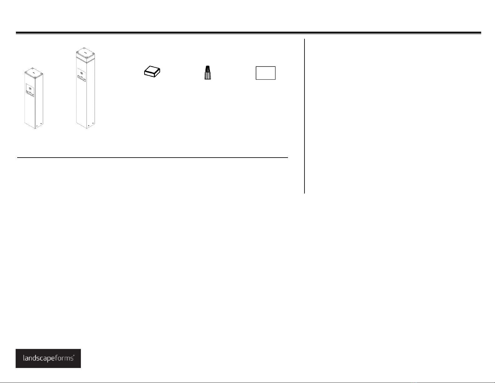
Includedcomponents
ToolsRequired
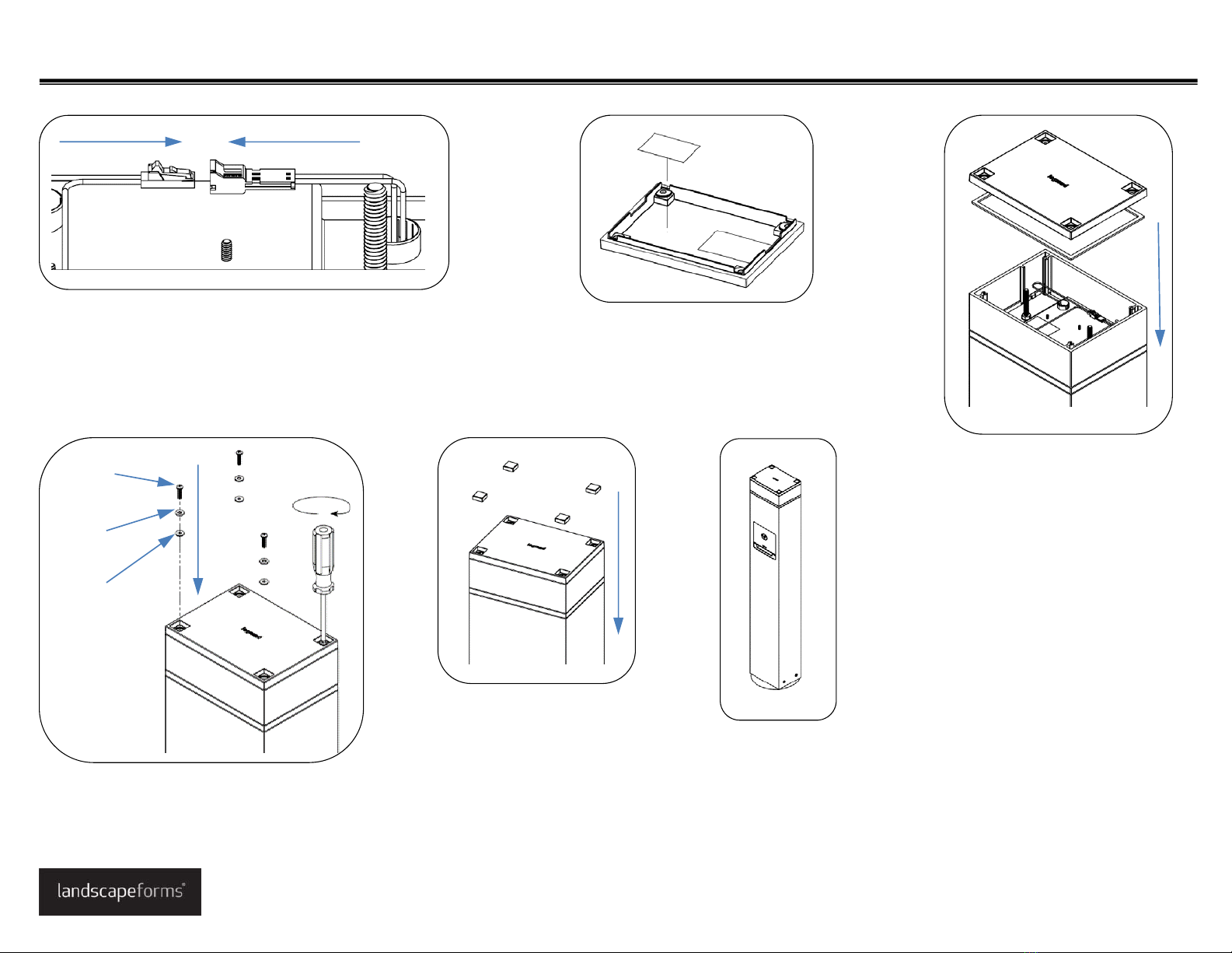
•Safetyglasses
•Wrenches,1/2”,9/16”
•Socketwrench,7/16”
•Screwdrivers,Phillipsandstraightblade
•Wiringtoolsandconnectors
•Level
•Grease
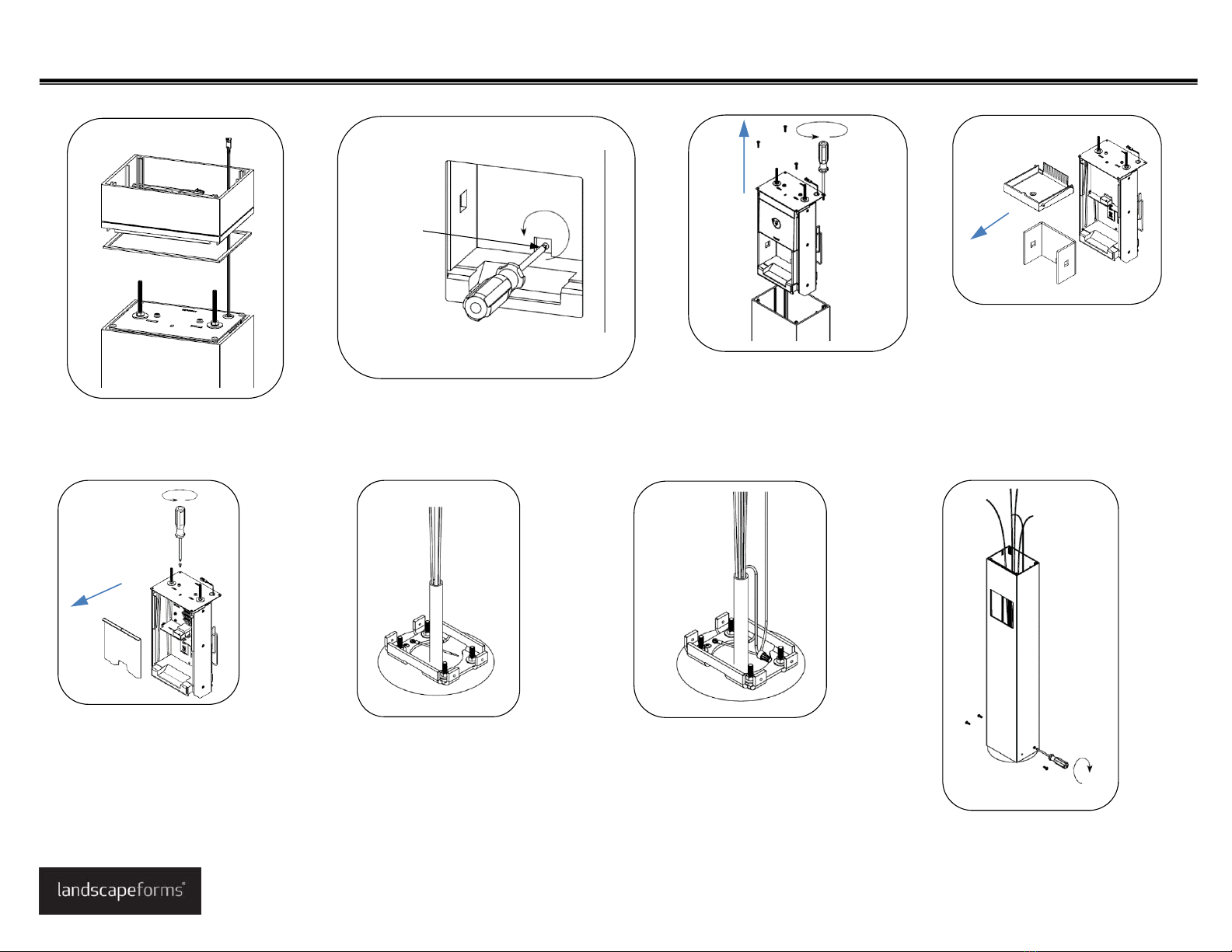
LandscapeFormsisnotresponsibleforsitepreparationand
footings.RefertotheinstallationguidefortheOutdoorPower
anchorkitforinstallingtheanchorbolts.
IMPORTANT! Pleasereadallinstructionsbeforebeginning
installation.
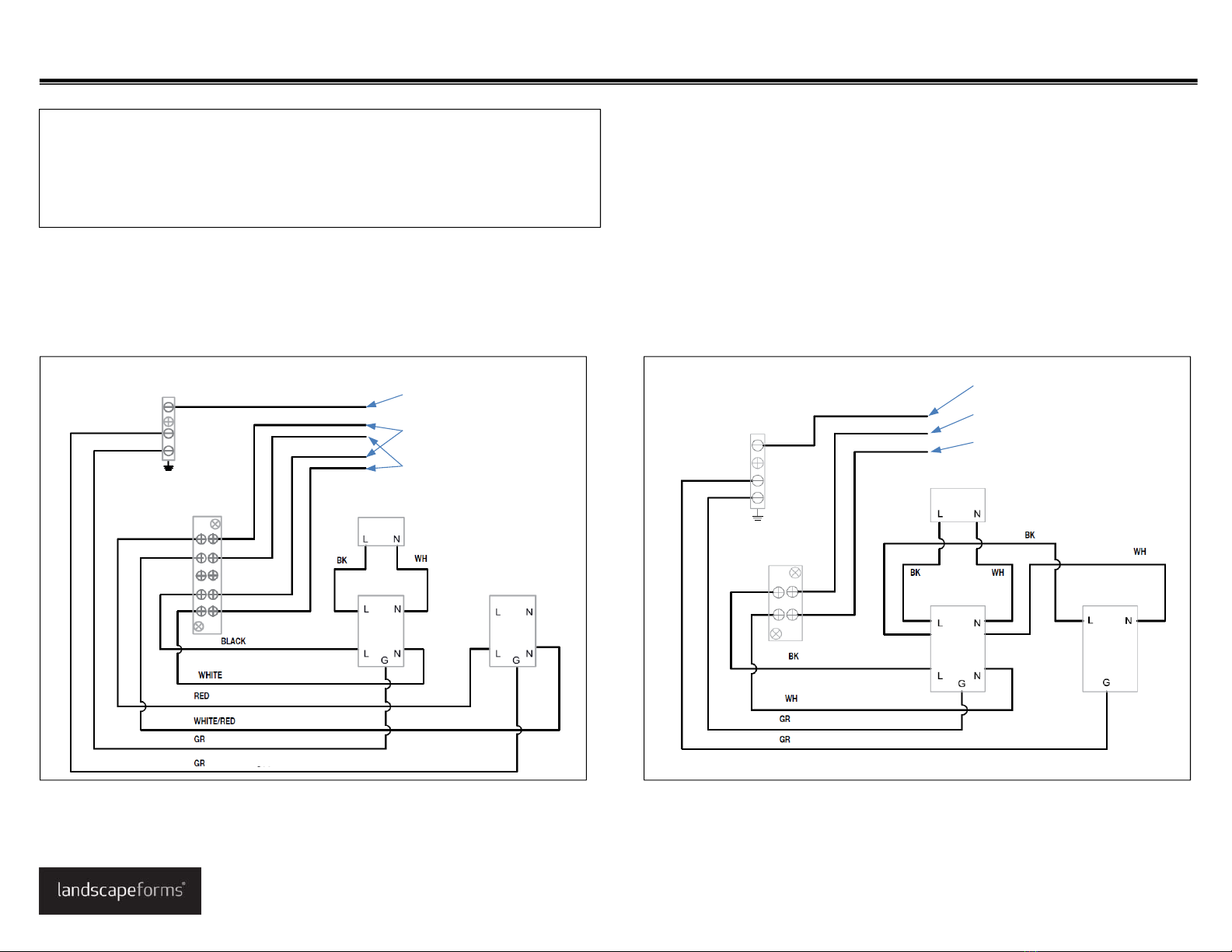
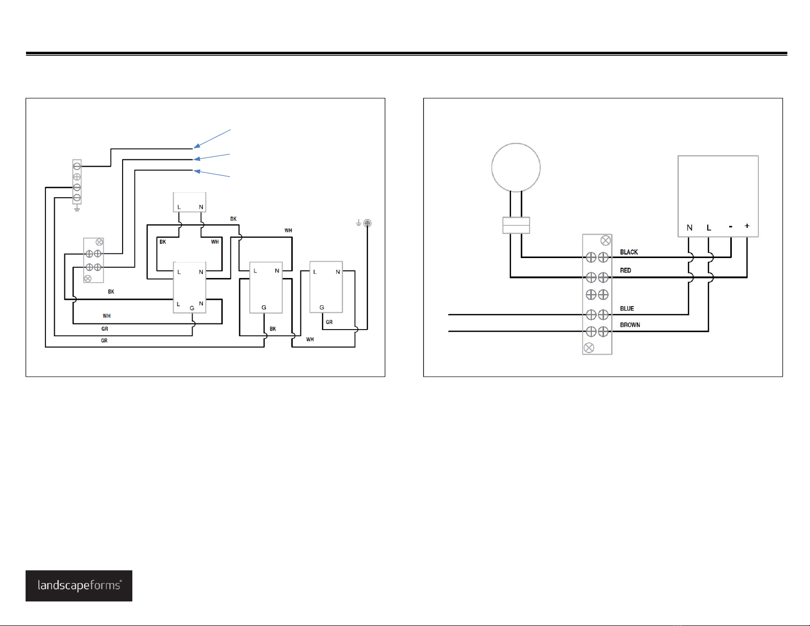
LegrandElectricalsystemsconformtoandshouldbeproperly
groundedincompliancewithrequirementsofthecurrentNational
ElectricalCodeorcodesadministeredbylocalauthorities.
Allelectricalproductsmaypresentapossibleshockorfirehazardif
improperlyinstalledorused.Legrandelectricalproductsmaybear
themarkofanationallyRecognizedTestingLaboratoryandshould
beinstalledinconformancewithcurrentlocaland/ortheNational
ElectricalCode.
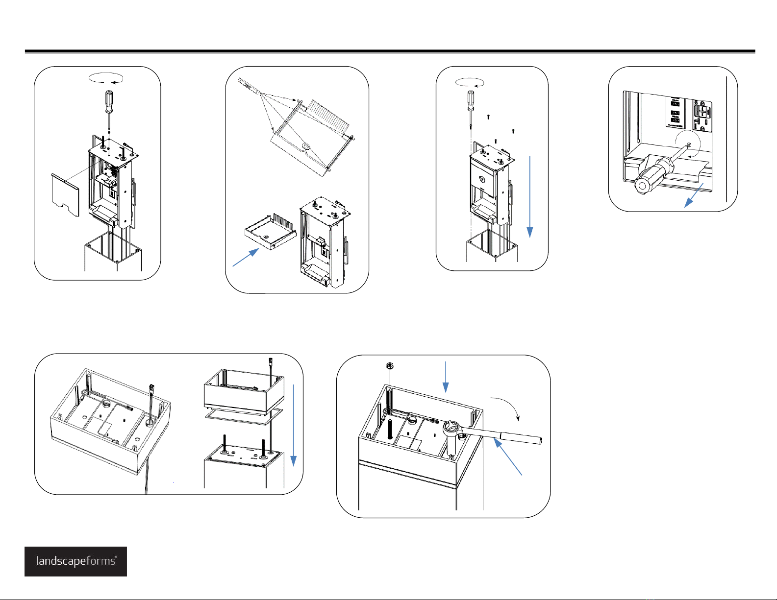
ASSEMBLEWITHCARE! Toprotectthisfinishduringassembly,place
unwrappedpowdercoatedpartsonpackagingfoamorothernon‐marring
surface.Donotplaceorslidepowdercoatedpartsonconcreteorother
hardortexturedsurface– thiswilldamagethefinishcausingrusttooccur.
Usetouch‐uppaintonanygougesinthefinishcausedbyassemblytools.
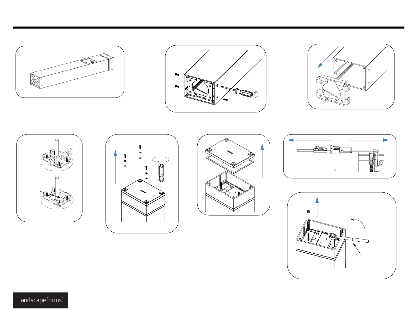
Installation Guide
Outdoor Power Power Pedestal and Outdoor Charging Station with Accent Light
www.landscapeforms.com Ph: 800.521.2546
Date: June 10, 2016
Page 1 of 8
4X– Rubbercap
Power
Pedestal
1X–WireNut 1X– WarningLabel
Chargingstation
withaccentlight