LANDTEC GEM2000 User manual

Form 080/01
Complimentary Reference Material
This PDF has been made available as a complimentary service for you to assist in
evaluating this model for your testing requirements.
T G offers a wide range of test equipment solutions, from renting short to long
term, buying refurbished and purchasing new. Financing options, such as
Financial Rental, and Leasing are also available on application.
T G will assist if you are unsure whether this model will suit your requirements.
Call T G if you need to organise repair and/or calibrate your unit.
If you click on the “Click-to-Call” logo below, you can all us for FREE!
TMG Corporate Website TMG Products Website
Disclaimer:
All trademarks appearing within this PDF are trademarks of their respective owners.

GEM2000
GEM2000 Plus
GAS ANALYZER & EXTRACTION MONITOR
OPERATION MANUAL
For
Serial Numbers 10000 and up

GEM2000 & GEM2000 Plus Operation Manual
Page ii
©Copyright 2007 by LANDTEC
All rights reserved. No part of this book may be used or reproduced in any form or by any means, or stored
in a database or retrieval system, without consent of the publisher. Making copies of any part of this book
for any purpose other than your own personal use is a violation of United States copyright laws.
LANDTEC and GEM are registered with the U.S. Patent and Trademark Office.
For further information contact:
LANDTEC North America
850 S. Via Lata, Suite 112
Colton, CA 92324
USA
Tel: 800-821-0496 or +1-909-783-3636
Web: www.ces-landtec.com
LANDTEC Europe
Formerly Geotechnical Instruments
Sovereign House Queensway
Leamington Spa, Warwickshire CV31 3JR,
England
Tel: +44(0)1926 338111
Web: www.geotech.co.uk
LANDTEC South America
LANDTEC Produtos e Servicos Ambientais Ltda.
Rua Pedroso de Carmargo, 237 - Chácara
Santo Antonio - SP/SP CEP 0417-010
Brazil
Phone: +55(11) 5181-6591
Web: www.landtecbrazil.com.br
LANDTEC Release Date: March 5, 2008

GEM2000 & GEM2000 Plus Operation Manual
Page iii
Contents
1 INTRODUCTION....................................................................................................................... 1
2 GENERAL OPERATIONAL FEATURES.................................................................................. 2
2.1 PHYSICAL CHARACTERISTICS OF THE GEM2000 / GEM2000 PLUS.....................................................2
2.2 STORAGE ........................................................................................................................................ 2
2.3 BATTERY/CHARGING ........................................................................................................................ 3
2.4 INSTRUMENT CERTIFICATION............................................................................................................. 3
2.5 SAFETY INFORMATION ...................................................................................................................... 3
2.6 TURNING THE INSTRUMENT ON/OFF.................................................................................................. 3
2.7 WARM-UP SELF TEST .......................................................................................................................4
2.8 WARNING AND ERROR DISPLAY ........................................................................................................ 4
2.8.1 WARNING Displayed ..............................................................................................................4
2.8.2 ERROR Displayed................................................................................................................... 4
2.9 SERVICE INFORMATION SCREEN ....................................................................................................... 5
2.10 TECHNICIAN ID SCREEN................................................................................................................ 5
2.11 GAS READING SCREEN ................................................................................................................. 5
2.11.1 Keypad Lock............................................................................................................................ 5
2.12 OPTIONAL GAS PODS.................................................................................................................... 6
2.13 MEMORY...................................................................................................................................... 6
2.13.1 Cold Start ................................................................................................................................ 6
2.13.2 Recover Readings...................................................................................................................7
2.13.3 Print Readings.........................................................................................................................7
2.14 RF INTERFERENCE ....................................................................................................................... 7
3 THE LANDTEC SYSTEM GAS ANALYZER MANAGER SOFTWARE ................................... 8
3.1 CONFIGURATION OPTIONS................................................................................................................ 8
3.2 ONLINE USERS................................................................................................................................. 8
3.3 OFFLINE USERS............................................................................................................................... 8
3.3.1 Installation with the CD............................................................................................................ 8
3.3.2 Start Up................................................................................................................................... 9
3.3.3 Navigation ............................................................................................................................. 10
The LANDTEC System Gas Analyzer Manager User Interface allows for easy access and navigation to
various utilities to use the LANDTEC portable instrument on a day to day basis. The following is a
general description of the user interface. ............................................................................................. 10
3.4 CONNECTING TO THE INSTRUMENT.................................................................................................. 10
1. Connect the GEM2000 with the RS-232 Download Cable to your Computer................................ 11
2. Instrument must be powered ON and in the Gas Reading screen ................................................ 11
3. Launch the LSGAM software by clicking on the icon on your desktop .......................................... 11
3.5 CREATE A PROJECT / SELECT A PROJECT........................................................................................ 12
3.6 SETUP IDS..................................................................................................................................... 12
3.6.1 Creating Comments............................................................................................................... 13
3.6.2 Creating IDs .......................................................................................................................... 13
3.6.3 IDS FROM DATAFIELD CS 3.2X: ......................................................................................... 16
3.6.1 IDS ALREADY IN THE INSTRUMENT:................................................................................. 17
3.7 CREATING YOUR SITE QUESTIONS.................................................................................................... 19
3.8 SENDING IDS TO THE INSTRUMENT.................................................................................................. 23
3.8.1 Clearing ID s from your instrument or Deleting a Project ....................................................... 25
3.9 INSTRUMENT SETTINGS .................................................................................................................. 26
3.9.1 Alarm Settings....................................................................................................................... 26
3.9.2 Data Logging......................................................................................................................... 27
3.9.1 Set Date/Time in the instrument ............................................................................................ 28
3.10 MISC OPTIONS ........................................................................................................................... 28

GEM2000 & GEM2000 Plus Operation Manual
Page iv
3.11 UNITS OF MEASUREMENT ............................................................................................................29
3.12 DOWNLOADING READINGS ...........................................................................................................29
4 GENERAL OPERATIONS MENU........................................................................................... 32
4.1 ZERO TRANSDUCERS......................................................................................................................32
4.2 UPDATE SITE DATA.........................................................................................................................32
4.3 DATA LOGGING (GA MODE ONLY) ....................................................................................................32
4.4 OPERATING LANGUAGE...................................................................................................................32
4.5 VIEW DATA.....................................................................................................................................32
4.6 ADJUST CONTRAST.........................................................................................................................32
4.7 FIELD CALIBRATION.........................................................................................................................33
4.7.1 Zero Channels .......................................................................................................................33
4.7.2 Span Channels ......................................................................................................................33
4.7.3 Factory Settings.....................................................................................................................33
4.7.4 Last Field Cal.........................................................................................................................33
4.8 MODE OF OPERATION .....................................................................................................................33
4.9 INFORMATION SCREEN....................................................................................................................34
4.10 EXIT MENU .................................................................................................................................34
5 TAKING PROBE READINGS (GA MODE)............................................................................. 35
5.1 PRELIMINARY CHECKS ....................................................................................................................35
5.2 UPDATE SITE DATA.........................................................................................................................35
5.3 TAKING READINGS –WITH ID ..........................................................................................................35
5.4 TAKING READINGS –WITHOUT ID....................................................................................................36
5.5 TEMPERATURE PROBE READING......................................................................................................37
5.6 CROSS-GAS EFFECTS.....................................................................................................................37
5.6.1 Methane, Carbon Dioxide and Oxygen...................................................................................37
5.6.2 H2S, CO and other Optional Gas Pods...................................................................................38
5.6.3 GEM2000 Plus Internal Electrochemical Cells for Measuring H2S and CO.............................38
6 TAKING EXTRACTION WELL READINGS (GEM MODE)..................................................... 39
6.1 PRELIMINARY CHECKS ....................................................................................................................39
6.2 UPDATE SITE DATA.........................................................................................................................39
6.3 TAKING GAS AND FLOW READINGS (GEM MODE).............................................................................39
7 FIELD OPERATIONS.............................................................................................................. 41
7.1 LANDFILL GAS GENERATION............................................................................................................41
7.2 SUBSURFACE FIRES........................................................................................................................41
7.3 TECHNIQUES FOR CONTROLLING LANDFILL GAS ...............................................................................41
7.3.1 Controlling by Wellhead Valve Position..................................................................................42
7.3.2 Controlling by Wellhead Vacuum ...........................................................................................42
7.3.3 Controlling by Gas Composition.............................................................................................42
7.3.4 Controlling by Flow Rate........................................................................................................42
7.4 WELL FIELD MONITORING................................................................................................................43
7.5 TYPICAL FIELD READINGS................................................................................................................43
7.6 ABBREVIATED FIELD READINGS .......................................................................................................43
7.7 WELL FIELD ADJUSTMENT CRITERIA ................................................................................................44
7.8 ESTABLISHING TARGET FLOWS........................................................................................................45
7.9 WELL FIELD OPTIMIZATION..............................................................................................................45
7.10 MIGRATION CONTROL—DEALING WITH POOR METHANE QUALITY ..................................................45
7.11 WELL FIELD ADJUSTMENT—PURPOSE AND OBJECTIVES ...............................................................45
8 TROUBLESHOOTING ............................................................................................................ 46

GEM2000 & GEM2000 Plus Operation Manual
Page v
9 SERVICE & MAINTENANCE...................................................................................................47
9.1 FACTORY SERVICE......................................................................................................................... 47
9.2 FACTORY SERVICE FACILITIES ........................................................................................................ 48
9.3 USER MAINTENANCE ...................................................................................................................... 48
10 TECHNICAL SPECIFICATIONS ..........................................................................................49
10.1 PHYSICAL................................................................................................................................... 49
10.2 GENERAL ................................................................................................................................... 49
10.3 POWER SUPPLY.......................................................................................................................... 49
10.4 GAS RANGES ............................................................................................................................. 49
10.5 PUMP......................................................................................................................................... 50
10.6 OPERATING CONDITIONS............................................................................................................. 50
10.7 OPTIONAL GAS PODS.................................................................................................................. 50


GEM2000 & GEM2000 Plus Operation Manual
Page 1
1 Introduction
LANDTEC is the premier manufacturer of products, instruments and software for landfill gas extraction and
for regulatory monitoring compliance. LANDTEC has provided the landfill industry with a technologically
innovative family of products for more than a decade. These products are the result of field-proven
experience in design, operation and maintenance of landfills for environmental compliance.
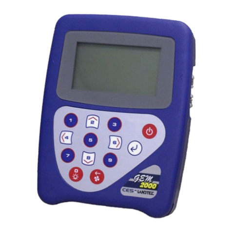
The GEM2000 and GEM2000 Plus, designed by LANDTEC, are specifically for use on landfills to monitor
landfill gas (LFG) extraction systems, flares and migration control systems. Both instruments sample and
analyze the Methane, Carbon Dioxide and Oxygen content of LFG. The GEM2000 Plus also samples and
analyzes Carbon Monoxide and Hydrogen Sulfide. The readings are displayed and can be stored in the
instrument and downloaded to a personal computer for reporting, analyzing and archiving.
The GEM2000 / GEM2000 Plus instrument is shipped in a protective hard case with a foam interior that
offers additional protection, transportation convenience and component hardware storage. When properly
sealed, the hard case is watertight. The hard case is equipped with a pressure relief valve (located under
the handle on the case) that is normally kept closed. If there is a change in elevation, the hard case may
not open until the pressure relief valve is opened to equalize internal pressure. When shipping a GEM2000
/ GEM2000 Plus back to LANDTEC for calibration or service, always ship it in the hard case to protect unit
from damage.
Carefully unpack the contents of the GEM2000 / GEM2000 Plus, inspect and inventory them. The following
items should be contained in your package:
The GEM2000 / GEM2000 Plus instrument
GEM2000 / GEM2000 Plus Operation Manual
Registration/Warranty Card
Soft carrying case with replaceable protective window and carrying strap
Clear ¼” vinyl sampling hose assembly (5 ft.) with external water trap filter assembly
Blue ¼” vinyl pressure sampling hose (5 ft.)
Spare internal particulate filter element
Polypropylene male connector (hose barb) connects to blue vinyl tubing
Spare external water trap filter element
100-240 volt battery charger
Software on CD-ROM
RS-232 serial cable for computer/instrument communications
Temperature probe (optional)
Hard carrying case
Complete the Registration/Warranty Card and return it to LANDTEC. The model and serial numbers are
located on the back of the GEM2000 / GEM2000 Plus instrument.
Immediately notify shipping company if the GEM2000 / GEM2000 Plus unit or accessories are
damaged due to shipping. Contact LANDTEC immediately if any items are missing.
For questions regarding instrument operation and procedures, please contact LANDTEC at:
Customer Service or Technical Support
Factory Service (800) 821-0496 Extension 6131
(800) 821-0496 Extension 6141

GEM2000 & GEM2000 Plus Operation Manual
Page 2
2 General Operational Features
2.1 Physical Characteristics of the GEM2000 / GEM2000 Plus
2.2 Storage
Do not keep the instrument in the trunk of a car or shed because it may be exposed to temperature
extremes.
When not in use, instruments should be kept in a clean, dry and warm environment such as an office.
The instrument batteries should be discharged and fully charged at least once every four weeks regardless
of indicated charge state. The discharge function may be carried out with the use of the Data Logging
Function in GA mode of operation.

GEM2000 & GEM2000 Plus Operation Manual
Page 3
2.3 Battery/Charging
The Battery Charger IS NOT covered by the unit UL certification. Therefore, when connected to the
Battery Charger, the instrument IS NOT intrinsically safe and should not be used in confined
spaces.
The battery used in the GEM2000 / GEM2000 Plus is a Nickel Metal Hydride manufactured as an
encapsulated pack from six individual cells. This type of battery is not so susceptible to “memory effects” as
Nickel Cadmium batteries, although it is not recommended that the unit be given short-term charges. When
the flashing LED indicates “Trickle Charge” the charging is completed and the unit can be disconnected
from the charger.
The battery charger indicates when the unit is charging, charged or if there is a fault. A full charge should
take approximately 2 hours.
2.4 Instrument Certification
The GEM2000 / GEM2000 Plus is UL/Sira certified for use in hazardous locations. Specifically certified as
to intrinsic safety for use in hazardous locations Class I, Zone 1, AEx ib d IIA T1 (Ta=32°F to +104°F).
For the certification to remain intact it is vital the instructions in this manual are followed closely and repairs
of this equipment be carried out in accordance with the applicable code of practice by an approved repair
facility. See section 9.2 for a list of authorized repair locations.
It is the responsibility of the operator to determine the protection concept and classification required for a
particular application.
2.5 Safety Information
The GEM2000 / GEM2000 Plus is normally used for measuring gases from landfill sites. Inhaling these
gases, or gases from other sites may be harmful to health and in some cases may be fatal. It is the
responsibility of the user to ensure that he/she is adequately trained in the safety aspects of the gases
being used and that appropriate procedures be followed. In particular, where hazardous gases are being
used the gas exhausted from the analyzer must be piped to an area where it is safe to discharge the gas.
Hazardous gas can also be expelled from the instrument when purging with clean air.
2.6 Turning the Instrument On/Off
When switching the instrument on, a long beep will sound, followed by the LANDTEC logo being displayed
and the self-test will commence. Whenever a key is pressed the unit will emit a short ‘beep’ as an
acknowledgement. This function cannot be turned off.
When switching the instrument off, the On/Off button must be held down for approximately 2-3 seconds, at

GEM2000 & GEM2000 Plus Operation Manual
Page 4
which point a clean air purge will be carried out. If for any reason the instrument ‘locks-up’ and will not
switch off, press and hold the On/Off button for 15 seconds. This will force the instrument to switch off.
2.7 Warm-up Self Test
When switched on, the instrument will perform a predetermined self-test sequence taking approximately 30
seconds, during this time many of the instrument’s functions are tested, including:
General operation
Pump function
Gas flow measurement
Calibration
Backlight function
Solenoid function
During the self-test, the following information is also displayed:
Software version
Serial Number. Calibration due date.
Date format.
Operating language.
Communication Baud rate.
2.8 Warning and Error Display
During the self-test, if any operational parameters are out of specification or the pre-programmed
recommended calibration/service date has passed errors or warnings may be displayed. Only three
errors/warnings can be displayed at any time. To ascertain if more errors occurred, use the ‘’ and ‘’ key to
scroll up/down the list, to exit from this screen press the “Enter/Store” key ‘’.
2.8.1 WARNING Displayed
All warnings displayed will be prefixed by the word ‘‘WARNING‘followed by a relevant description. Two
types of warnings may be displayed.
1. General warnings that may not have an effect on the instrument’s function and those where the self-
test has detected a function that is outside the usual programmed operating criteria (e.g. Battery
charge low, memory nearly full, etc.).
2. Specific warnings of operational parameters that can affect the performance of the instrument (e.g.
O2Cell out of calibration, CH4out of calibration, CO2out of calibration, etc.).
The most likely reason for the errors is either an incorrect user calibration, or sensor failure. If an incorrect
user calibration has caused the warning, it should be correctable by way of returning the instrument to
factory settings, zeroing or carrying out a user calibration as necessary for the relevant function.
2.8.2 ERROR Displayed
All errors displayed will be prefixed by the word ‘ERROR‘ followed by a number and description. The errors
detected by the self-test are usually caused by a user calibration being out of specification or possibly
memory corruption. This will have an effect on the functionality of the instrument and should be corrected
before use (e.g. 01 - User cal data, CH4reading or channel out of specification, 02 - User cal data, CO2
reading out of specification).
If any other Warnings or Errors are displayed, contact a LANDTEC Authorized Service Facility for further
information.

GEM2000 & GEM2000 Plus Operation Manual
Page 5
2.9 Service Information Screen
Upon self-test completion, the GEM2000 / GEM2000 Plus will display service information including when
the next manufacturers service is due, what type of service agreement the instrument is under (if
applicable), and when the last factory gas check was performed. To exit from this screen press the
“Enter/Store” key ‘’.
2.10 Technician ID Screen
The Technician ID screen is displayed after the Service Information screen. While it is not necessary to
input a Technician ID it is possible to select a technician from a predetermined list (created in LSGAMS) or
input up to four characters to identify the technician performing the readings. This ID will be appended to all
readings that are taken until the instrument is turned off. To change the Technician ID simply turn the
instrument off and back on again. The Technician ID can be input through a virtual key board shown on the
instruments display. Letters or numbers can be selected by using the ‘’ and ‘’ key to scroll up/down and
the ‘’ and ‘’ to scroll left and right. Pressing the “Enter/Store” key ‘’ will select the highlighted character.
Once the Technician ID is selected, or to bypass selecting any characters press the ‘’ button.
2.11 Gas Reading Screen
After inputting or bypassing the Technician ID, the instrument will go into the Gas Reading screen, also
considered the normal operation screen. All operations are carried out from this starting point. The
following information is displayed in various boxed sections at this time:
Current programmed time and date
Current selected ID code
Pump status
Pump run time
Three main constituent gases –CH4, CO2, O2(in %)
Two minor gases –CO & H2S and indication of H2 (GEM2000 Plus only)
Balance gas
Last read time/date (if previous data is in memory)
Technician ID
External devices (displays pod type or temperature probe readings when attached)
% LEL CH4(if selected through LSGAM)
Barometric pressure reading.
Current relative pressure reading (GA mode only)
Gas Pod or Temperature Probe reading (if connected)
Battery Charge graph (5 segment, flashes at 20% remaining)
Memory Usage graph (5 segment, flashes at 5% remaining)
Other options:
Menu Allows access to all instrument user functions.
Next ID Allows the next ID to be selected (if IDs are available).
Measure Flow For GEM mode only.
Previous Reading Allows the previous reading of the selected ID to be viewed (if data is available).
Store Reading Stores the current displayed reading. (GA mode only)
2.11.1 Keypad Lock
After the instrument enters into the Gas Reading Screen, and from this point forward, the keypad can be
locked by pressing and holding the backlight key for approximately 2 seconds. A message will display at
the bottom of the display instructing you that to release the lock you will need to press and hold the
backlight button.

GEM2000 & GEM2000 Plus Operation Manual
Page 6
2.12 Optional Gas Pods
Optional Gas Pods are available for use with the GEM2000 / GEM2000 Plus. These pods are available in
seven different gases with eight different PPM ranges. Connection to the instrument is made via the data
port and exhaust port. The detected PPM level is displayed in the upper right area of the gas read screen
and is saved in the same manner as the other gas readings. The Gas Pods are not classified as
intrinsically safe they should not be attached or detached from the instrument in hazardous areas.
Gas Type Range (PPM) Resolution (PPM)
H2S 0-50 0.1
0-200 1.0
0-5000 35
CO 0-1000 1.0
SO20-20 0.1
0-100 1.0
H20-1000 1.0
HCN 0-100 1.0
Gas Pods are intended for use as an inexpensive detection means and not for regulatory reporting
purposes. If the GEM2000, fitted with a Gas Pod, indicates the presence of the selected gas, further testing
should be performed with regulatory approved instrumentation. LANDTEC recommends that field
calibration be performed using the relevant gas and concentration, prior to sampling with a Gas Pod. If
calibrated properly the accuracy of these Gas Pods are typically 5-10% Full Scale.
2.13 Memory
The instrument's memory is volatile. It is maintained by a battery back-up system, which will maintain the
memory while the battery is being changed.
The memory is not to be used as a permanent storage medium and any data should be transferred to a
more permanent storage medium as soon as possible. An Instrument should never be stored for prolonged
periods with valuable data in its memory.
Although unlikely, sudden shocks, high levels of electromagnetic interference or static discharge may cause
memory corruption or loss. If this occurs, the instrument should be Cold Started and the calibration reset to
factory settings before further use. Cold starting will erase all data in the instrument including
resetting the time and date to the default value.
2.13.1 Cold Start
THIS FUNCTION SHOULD BE USED ONLY AS A LAST RESORT.
(For Gas Calibration Error Messages, confirm that Factory Settings and User Calibration are done).
A Cold Start should only be carried out to correct an instrument if no other course of action has proved
successful. This function WILL ERASE the instrument memory entirely. After a cold start is performed the
user will need to reset the instrument to factory settings, perform a field calibration and reset the internal
time/date to the default settings. Please note that the time/date may only be updated through the
communication software. It cannot be updated manually.
To carry out a cold start, turn the instrument on, before the instrument enters into the self-test screen press
and continue to hold the ‘’ key until a pass code entry screen is displayed. At this point the ‘’ key may be
released. Enter the passcode 12345 and press ‘’ to confirm.
After the pass-code entry has been accepted, the instrument serial number will be displayed along with the
hours in use, pump run time and service dates. There are four options from this screen;

GEM2000 & GEM2000 Plus Operation Manual
Page 7
1 - Cold Start
2 - Recover readings
3 - Print readings
0 - Exit
ONLY select option ‘1’ if a Cold Start is to be carried out. Press key ‘1’ to confirm this operation or press
key ‘0’ to continue with normal operation. If you select ‘1’ to confirm the cold start a message will be
displayed confirming the cold start operation and all memory will be cleared. The instrument will continue to
the technician ID screen.
2.13.2 Recover Readings
THIS FUNCTION SHOULD BE USED ONLY AS A LAST RESORT.
Recover readings is a low level memory function that should only be used as a last resort if all your
readings were inadvertently deleted and you know how many readings you had. This function moves the
memory buffer and can cause instrument corruption. Contact LANDTEC before attempting to recover
readings.
2.13.3 Print Readings
This function is best performed using an appropriate RS232 cable (included with new instruments, also
available from LANDTEC) and the LSGAM software. See section 3.12 Downloading Readings for more
detail.
2.14 RF Interference
The gas sensors, especially the Methane sensor, are sensitive to RF interference.
Any device that transmits radio waves can cause your gas readings to fluctuate. Cell phones are the most
common cause of the problem. You should never use your cell phone while you are taking gas readings.

GEM2000 & GEM2000 Plus Operation Manual
Page 8
3 The LANDTEC System Gas Analyzer Manager Software
3.1 Configuration Options
The GEM2000 and LANDTEC System Gas Analyzer Manager (LSGAM) software can be utilized in a
number of ways:
Configured for operation with the LANDTEC System online service;
Used offline as a local application storing information on the desktop/laptop computer;
Used out of the box without software; (this does not allow the user to generate flow rate values or
select comments with the instrument and also prevents downloading of readings to the computer. It
also does not allow the user to correct the time and date or to clear the memory, unless cold
started.)
3.2 Online Users
The procedures included in the section are intended for those connected to the LANDTEC System online
service. The LANDTEC System is an online collaboration tool to Collect, Validate, Analyze, and
Communicate information based on field data obtained using LANDTEC instrumentation.
If you currently are a registered user on the LANDTEC System, please log in at
https://www.landtecsystem.com/. If you are not currently using the LANDTEC System, you may register by
contacting LANDTEC in the US: 800-821-0496 or International: +1-909-783-3636.
Online reference for using LANDTEC System Gas Analyzer Manager (LSGAM) with the LANDTEC System
can be found under the About Help & Support menu within the LANDTEC System.
If you do not have login information please contact Technical Support at +1-909-783-3636 extension 6131.
3.3 Offline Users
The procedures included in the section describe use of the LANDTEC System Gas Analyzer Manager
(LSGAM) Software while NOT connected to the LANDTEC System online service.
3.3.1 Installation with the CD
NOTE: The computer may need some administrative privileges to install the program.

GEM2000 & GEM2000 Plus Operation Manual
Page 9
Insert the CD into your CD ROM drive and wait for the setup to auto start. Click on the Launch Setup button
and follow the onscreen instructions. Once the software is installed you will have a shortcut icon on your
desktop which you will use to start the LSGAM instrument program.
The Java programming is an import part of this software and will be loaded with the CD install. The java
icon, shown below, will be in the task tray at the bottom of your computer screen where your time is shown.
There will also be a GAM log icon, shown below, that will be created on your desk top during installation.
.
3.3.2 Start Up
Starting LSGAM can be easily done by doing one of the following:
Double-Click on the Desktop icon.
OR - go to;
Start All Programs LANDTEC LANDTEC System Gas Analyzer Manager

GEM2000 & GEM2000 Plus Operation Manual
Page 10
3.3.3 Navigation
The LANDTEC System Gas Analyzer Manager User Interface allows for easy access and navigation to
various utilities to use the LANDTEC portable instrument on a day to day basis. The following is a general
description of the user interface.
LANDTEC System Login
When LSGAM is used with the LANDTEC System online service, the username and password will be
entered in the screen below, if you are using LSGSM as a desktop application the User Id and Password
fields do not need to be filled in.
The Progress section indicates the status of the current process. For example, when starting up LSGAM,
this will show you the activity of the software.
The Instrument section displays whether or not an instrument is connected. This also downloads the IDs,
readings, and comments. If an instrument is found the following is shown:
Instrument Type:
Serial Number:
Version:
Operating Mode:
Instrument Date:
Service Due Date:
Number of IDs:
Number of Readings:
Available Memory:
Battery Level:
3.4 Connecting to the Instrument

GEM2000 & GEM2000 Plus Operation Manual
Page 11
1. Connect the GEM2000 with the RS-232 Download Cable to your Computer
2. Instrument must be powered ON and in the Gas Reading screen
3. Launch the LSGAM software by clicking on the icon on your desktop
This is the first screen you will see when starting the program.
Once the software is installed on your computer with an internet connection this instrument communications
program has Auto application updates. This enables you to always have the most current version of the
instrument communications LSGAM.
If an update to LSGAM is available, you will see this notice when connected to the internet.
Click on OK this will return you to the desktop and you will then need to click on the LSGAM shortcut
again.
The GEM must be connected to computer and turned ON. It must also be in the Gas Reading screen. The
LSGAM software will automatically download any information in the instrument including readings,
comments and IDs.
A new instrument containing no information will display only the instrument information: Serial Number,
Version, Operating Mode, Instrument Date, Service Due Date, Number of IDs, Number of Readings,
Available Memory, and Battery Level.

GEM2000 & GEM2000 Plus Operation Manual
Page 12
3.5 Create a Project / Select a Project
Projects are a collection of Device IDs and their associated reading history. A project can be created using
LSGAM to contain a group of sequenced IDs and chronological history of instrument readings.
To create a Project, click on the Project menu and select New Project.
Upon selecting New Project… you will be prompted to enter a Project Name and select from one of three
options.
Create a New Empty Project
This option creates an blank project where you configure all IDs and Comments.
Create a New Project with comments and site questions from a Current Project
Selecting this option allows the user to create a new project that will have the same Comments and Site
Questions as an existing project.
Create a New Project from the data in a GEM2000
This option will create a New Project and automatically associate the IDs, Comments, and Site Questions
that exist in the connected portable instrument.
3.6 Setup IDs
An ID represents a physical sampling point in the field. An ID can be allocated to field components such as
extraction wellheads, gas transmission lines, or passive monitoring probes. LSGAM allows users to
configure an ID for each sampling point in order to obtain accurate readings with LANDTEC portable

GEM2000 & GEM2000 Plus Operation Manual
Page 13
instrumentation
IDs are created, modified, and removed from the Project Setup tab in the software.
3.6.1 Creating Comments
Comments should be setup prior to creating new IDs.The user can define Comments that can be
associated with a reading in the portable instrument.
If you selected Create a New Project when creating your project, you will need to click on the Create
Comments button. Comments can be entered in this setup screen or loaded from a file and will be displayed
in the user interface.
3.6.2 Creating IDs
There are several ways to input IDs to the Project. The following describes each process:
Creating new IDs with LSGAM
To create a new ID using the LANDTEC System Gas Analyzer Manager, Right Click on the left ID pane
beneath your active project and select the Add New ID option.
The Add New ID form will be displayed. From the ID Information tab of this form, entry of the following is
available:
Other manuals for GEM2000
1
This manual suits for next models
1
Table of contents
Other LANDTEC Measuring Instrument manuals

LANDTEC
LANDTEC GEM5000 User manual

LANDTEC
LANDTEC GEM2000 User manual

LANDTEC
LANDTEC BIOGAS 3000 User manual

LANDTEC
LANDTEC Geotech G100 Series User manual

LANDTEC
LANDTEC FPM-2680 User manual

LANDTEC
LANDTEC GEOTECH DIVEAIR 2 User manual

LANDTEC
LANDTEC GEM5000 User manual

LANDTEC
LANDTEC BIOGAS 5000 User manual