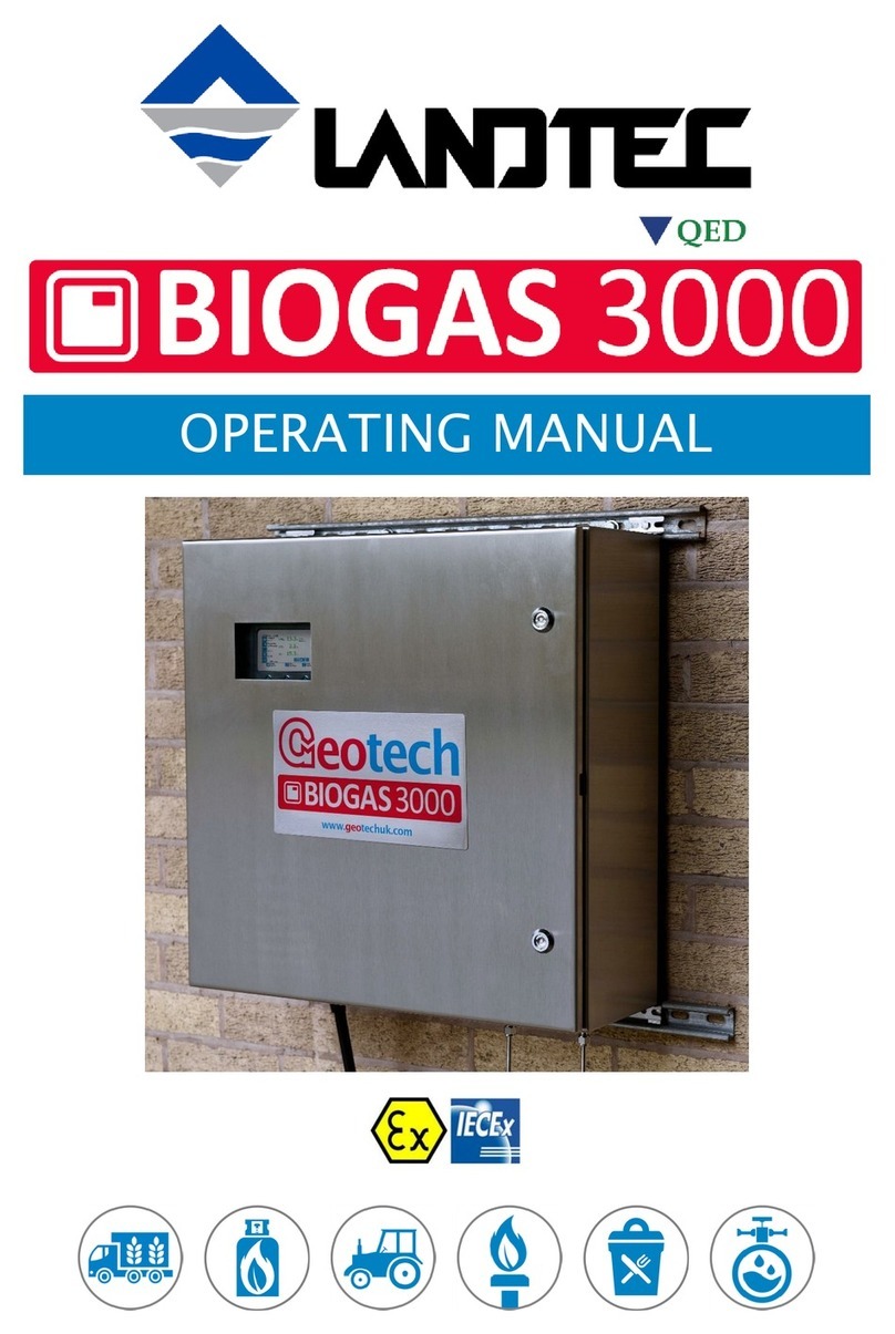
LANDTEC GEM2000 User manual

Copyright 2009 Geotechnical Instruments (UK) Limited
GEM2000 Range Gas Analysers
Operating Manual
GEM2000 LUS MC080126/00
Geotechnical Instruments (UK) Lt
Sovereign House
Queensway
Leamington Spa
Warwickshire
CV31 3JR
England
Tel: +44 (0)1926 338111
Fax: +44 (0)1926 338110
Email: [email protected]
Website: www.geotech.co.uk

OMGEMN1.41
GEM2000 Range Gas Analysers
age 2 Copyright 2009 Geotechnical Instruments (UK) Limited
This page is intentionally left blank.

GEM2000 Range Gas Analysers
OMGEMN1.41
Copyright 2009 Geotechnical Instruments (UK) Limited age 3
Table of Contents
1.0
MANUAL GUIDELINES....................................................................................... 7
1.1
Document History............................................................................................. 7
1.2
Safety Symbol ................................................................................................. 7
1.3
Notes.............................................................................................................. 7
2.0
INTRODUCTION................................................................................................ 8
2.1
Safety Instructions ........................................................................................... 8
2.2
Instructions for Safe Use – English Language ....................................................... 9
2.3
MCERTS .......................................................................................................... 9
3.0 THE GEM2000 RANGE GAS ANALYSERS............................................................. 10
3.1
The GEM2000 ................................................................................................ 10
3.2
The GEM2000 lus.......................................................................................... 11
3.3
Instrument Components – Standard roduct...................................................... 12
4.0
GEM2000 RANGE OPTIONAL PRODUCTS AND ACCESSORIES .......................... 13
4.1
Optional roducts ........................................................................................... 13
4.1.1
itot Tube (Optional)................................................................................. 13
4.1.2
Orifice late (Optional) .............................................................................. 13
4.1.3
Temperature robe (Optional) .................................................................... 13
4.1.4
Anemometer (Optional) ............................................................................. 13
4.1.5
External Gas od (Optional) ....................................................................... 14
4.1.6
H
2
S Filter (Optional).................................................................................. 14
4.1.7
Gas Analyser Manager – GAM (Optional)...................................................... 14
4.1.7.1
Event Log (Optional)............................................................................ 15
4.1.7.2
G S (Optional).................................................................................... 15
4.1.7.3
Technician Log-in (Optional) ................................................................. 15
4.2
Instrument Accessory roducts......................................................................... 16
5.0
GEM2000 RANGE INSTRUMENT FEATURES ..................................................... 17
5.1
hysical Characteristics of the Instrument anel ................................................. 17
5.2
anel Key Functions........................................................................................ 18
5.3
Instrument Connection oints .......................................................................... 19
6.0
GENERAL OPERATIONAL INSTRUCTIONS ....................................................... 20
6.1
Switching the Instrument On ........................................................................... 20
6.2
Switching the Analyser Off............................................................................... 20
6.3
Warm-up Self-test.......................................................................................... 20
6.4
Keypad Lock .................................................................................................. 21
6.5
Instrument Main Gas Read Screen .................................................................... 21
6.6
Cold Start...................................................................................................... 21
6.6.1
erform a Cold Start.................................................................................. 21
6.7
Storage......................................................................................................... 22
6.8
Battery/Charging............................................................................................ 22
6.9
Memory......................................................................................................... 22
6.10
Main Menu .................................................................................................. 23
6.10.1
Zero Transducer(s)................................................................................. 23
6.10.2
Update Site Data.................................................................................... 24
6.10.3
Data Logging......................................................................................... 24
6.10.4
View Data ............................................................................................. 25
6.10.5
rint Data ............................................................................................. 26
6.10.6
Adjust Contrast...................................................................................... 27
6.10.7
Field Calibration..................................................................................... 27

OMGEMN1.41
GEM2000 Range Gas Analysers
age 4 Copyright 2009 Geotechnical Instruments (UK) Limited
6.10.8
Mode of Operation.................................................................................. 27
6.10.9
Information Screen ................................................................................ 28
6.10.10
Operating Language ............................................................................ 28
6.10.11
Navigation.......................................................................................... 29
6.10.12
Exit Menu........................................................................................... 29
7.0
TAKING READINGS......................................................................................... 30
7.1
reliminary Checks Before Taking Readings (Best ractice).................................. 30
7.2
Update Site Data............................................................................................ 31
7.3
The Gas Flow Measurement Screen................................................................... 32
7.4
How to Use an Anemometer (Optional) ............................................................. 33
7.5
How to Use a itot Tube (Optional) ................................................................... 36
7.6
How to Use an H
2
S Filter (Optional) .................................................................. 37
7.6.1
Cross Gas Effects on Chemical Cells ............................................................ 37
7.6.2
Cross-Gas Effects on Methane, Carbon Dioxide and Oxygen............................ 38
7.7
How to Use a Temperature robe (Optional) ...................................................... 41
7.8
How to Use a Gas od (Optional)...................................................................... 42
7.9
How to Use the G S Feature (Optional) ............................................................. 43
7.9.1
GEM2000 Range G S Feature – Best ractice ............................................... 47
7.10
Taking Gas and Flow Measurement rocesses – Best ractice ............................ 48
7.10.1
Taking Gas and Flow Measurement with Borehole ID .................................. 49
7.10.2
Taking Gas and Flow Measurement Manual................................................ 50
8.0
CALIBRATION................................................................................................. 51
8.1
Calibration Introduction................................................................................... 51
8.2
Calibration Gases ........................................................................................... 51
8.3
Calibration Set-Up .......................................................................................... 52
8.4
Calibration Equipment..................................................................................... 53
8.5
Gas Analyser.................................................................................................. 53
8.6
Calibration Mixture rocesses – Best ractice ..................................................... 54
8.6.1
Low Level Calibration - Mixture 1 ................................................................ 55
8.6.1.1
Span Multi Gas.................................................................................... 58
8.6.2
Low Level Calibration - Mixture 2 ................................................................ 59
8.6.3
High Level Calibration - Mixture 3 ............................................................... 63
8.6.4
Calibration of CO – Mixture 100ppm............................................................ 67
8.6.5
Calibration of H
2
Compensated CO – Mixture CO 100ppm H
2
1000ppm ............ 69
8.7
Confirm Calibration......................................................................................... 72
8.7.1
Confirm Multi-Gas..................................................................................... 72
8.7.2
Confirm Channels Independently ................................................................ 72
8.8
Factory Settings ............................................................................................. 73
8.9
Last Field Calibration ...................................................................................... 73
8.10
Calibration Record ....................................................................................... 74
9.0
PROBLEM SOLVING ........................................................................................ 75
9.1
Warning and Error Display ............................................................................... 75
9.2
User Calibration Trouble Shooting..................................................................... 76
10.0
SERVICE ...................................................................................................... 77
11.0
WARRANTY POLICY ..................................................................................... 78
12.0
TECHNICAL SPECIFICATIONS ...................................................................... 79
12.1
GEM2000 Technical Specification ................................................................... 79
12.2
GEM2000 lus Technical Specification ............................................................ 81
13.0
EVENT LOG .................................................................................................. 83

GEM2000 Range Gas Analysers
OMGEMN1.41
Copyright 2009 Geotechnical Instruments (UK) Limited age 5
14.0
SAMPLE CERTIFICATE OF CALIBRATION...................................................... 86
15.0
IMPORTANT NOTICE TO ALL CUSTOMERS .................................................... 88
16.0
DECLARATION OF CONFORMITY – ENGLISH LANGUAGE .............................. 89
17.0
GEM2000 RANGE GLOSSARY OF TERMS ....................................................... 90
18.0
APPENDICES – SAFETY INSTRUCTIONS ....................................................... 97
18.1
Instructions for Safe Use – Italian Language ................................................... 97
18.2
Instructions for Safe Use – German Language ................................................102
18.3
Instructions for Safe Use – French Language..................................................107
18.4
Instructions for Safe Use – Spanish Language ................................................110

OMGEMN1.41
GEM2000 Range Gas Analysers
age 6 Copyright 2009 Geotechnical Instruments (UK) Limited
This page is intentionally left blank.

GEM2000 Range Gas Analysers
OMGEMN1.41
Copyright 2009 Geotechnical Instruments (UK) Limited age 7
1.0 Manual Gui elines
1.1 Document History
Issue
By Issue
Date Change
Control ID Issue
No.
Reason for Change
LA Apr 2010 OMGEMN 1.35 New Instructions
LA Apr 2010 OMGEMN 1.41 New Instructions
1.2 Safety Symbol
Information in this manual that may affect the safety of users and others is preceded by
the following symbol:
Warning
Failure to follow this information may result in physical injury which in some cases could
be fatal.
1.3 Notes
Important/useful information and instructions are shown clearly throughout the manual in
a note format.
For example:
Note: For further information please contact Technical Support at Geotech (UK) Limited
on +44(0)1926 338111 or email technical@geotech.co.uk

OMGEMN1.41
GEM2000 Range Gas Analysers
age 8 Copyright 2009 Geotechnical Instruments (UK) Limited
2.0 Intro uction
This manual explains how to use the GEM2000 range of landfill gas analysers for the following
model types:
•
••
•GEM2000
•
••
•GEM2000 lus
There are a number of versions of the GEM2000 analyser, and several options. Where a
section in the manual applies only to some of the versions, this is indicated in the section
heading.
The GEM2000 range has additional functionality to the GA2000 range gas analysers. The
GA2000 range measures gas concentrations only, whereas the GEM2000 range measures flow
and gas concentrations. The GEM2000 range measures flow and calculates the calorific
values of the gas as well as being a useful tool for balancing the field. The GEM2000 range
may be used to monitor, calculate, adjust and record the flow at each monitoring point.
This instrument may also be used in GA2000/GA2000 lus mode of operation.
‘Mode of Operation’ enables the operator to change the analyser between a gas extraction
monitor (a GEM2000 range gas analyser) to a landfill gas analyser (a GA2000 range gas
analyser).
Note: To change the instrument mode to a GA2000 range gas analyser, please refer to
section ‘6.10.8 Mode of Operation’ of this operating manual followed by the
‘GA2000 Range Gas Analysers Operating Manual’ for instructions on use.
2.1 Safety Instructions
Warning
The GEM2000 range of gas analysers can be used for measuring
gases from landfill sites and other sources as described in this
manual.
Inhaling these gases may be harmful to health and in some cases
may be fatal.
It is the responsibility of the user to ensure that he/she is adequately
trained in the safety aspects of the gases being used and appropriate
procedures are followed. In particular, where hazardous gases are
being used the gas exhausted from the analyser must be piped to an
area where it is safe to discharge the gas.
Hazardous gas can also be expelled from the instrument when
purging with clean air.
Note
:
Gas analysers are a sensitive piece of scientific equipment, and should be
treated as such.

GEM2000 Range Gas Analysers
OMGEMN1.41
Copyright 2009 Geotechnical Instruments (UK) Limited age 9
2.2 Instructions for Safe Use – English Language
(Reference European ATEX Directive 94/9/EC, Annex II, 1.0.6.)
The following instructions apply to equipment covered by certificate numbers Sira
06ATEX2202X:
•The equipment may be used with flammable gases and vapours with apparatus
group IIA and temperature class T1.
•The equipment is only certified for use in ambient temperatures in the range 0ºC to
+40ºC and should not be used outside this range.
•Installation shall be carried out in accordance with the applicable code of practice by
suitably trained personnel.
•Repair of this equipment shall be carried out in accordance with the applicable code
of practice.
•The manufacturer will specify those materials which are important to the type of
protection.
•When the GEM2000 or GEM2000 lus methane detector is in the hazardous area it
shall only be externally attached via ‘Connector D’ (the half moon) to devices that
are marked with the certificate number Sira 06ATEX2202X.
•If the equipment is likely to come into contact with aggressive substances, e.g. acidic
liquids or gases that may attack metals, or solvents that may affect polymeric
materials, then it is the responsibility of the user to take suitable precautions, e.g.
regular checks as part of routine inspections or establishing from the material’s data
sheet that it is resistant to specific chemicals that prevent it from being adversely
affected, thus ensuring that the type of protection is not compromised.
The GEM2000/GEM2000 Plus Gas Analyser has been certifie to Hazar ous Area Classification
II 2G Ex ib IIA T1 Gb (Ta = 0ºC to +40ºC)
It is vital the instructions in this manual are followed closely. It is the responsibility of the
operator to determine the protection concept and classification required for a particular
application.
2.3 MCERTS
MCERTS is the UK Environment Agency's Monitoring Certification Scheme. The scheme
provides a framework within which environmental measurements can be made in
accordance with the Agency's quality requirements. The scheme covers a range of
monitoring, sampling and inspection activities.
This certification does not apply to the GEM2000 version. The GEM2000 lus version of
this instrument is MCERTS certified only if:
•
••
•The MCERTS logo appears on the screen after initial power on.
•
••
•The internal analyser Firmware software version is 3.02 or later.
Note: MCERTS - Cross sensitivity tests using hydrogen sulphide were not
carried out on this instrument. Therefore, users should be aware if H
2
S
is present on sites, there may be an interferent effect.
The GA2000 lus has been certified to version 1 of the ‘ erformance Standards for ortable
Emission Monitoring Systems’.
Note: lease refer to the Glossary of Terms for further information on MCERTS.

OMGEMN1.41
GEM2000 Range Gas Analysers
age 10 Copyright 2009 Geotechnical Instruments (UK) Limited
3.0 The GEM2000 Range Gas Analysers
3.1 The GEM2000
The GEM2000 is designed for gas extraction systems, flares and migration control systems.
This unit allows standard landfill monitoring and, in the GEM mode, can display calorific
gas content of a gas extraction system. This analyser is ideal for maximising extraction
efficiency and quality for waste to energy systems.
Benefits:
•
••
•Aids balancing of gas field.
•
••
•Real time adjustments can be made.
•
••
•Easy to read flow and power readings.
•
••
•Maximise power output from site.
Features:
•
••
•ATEX certified.
•
••
•CH
4
, CO
2
and O
2
measured.
•
••
•eak gases recorded.
•
••
•Records static and differential pressure.
•
••
•Calculates gas flow m
3
/hr.
•
••
•Calculates calorific value (KW or BTU).
Applications:
•
••
•Gas extraction sites.
•
••
•Flare/engine compound.

GEM2000 Range Gas Analysers
OMGEMN1.41
Copyright 2009 Geotechnical Instruments (UK) Limited age 11
3.2 The GEM2000 Plus
The GEM2000 lus is designed to monitor landfill gas extraction systems. The GEM2000 lus
gives increased reliability for carbon monoxide (CO) readings. It retains the features of the
field proven GEM2000.
Benefits:
•
••
•Allows balancing of gas extraction site.
•
••
•Maximise power generation from site.
•
••
•Simultaneous display of gases.
•
••
•Storage of changes in set-up of gas field.
•
••
•Field proven.
•
••
•Standardises monitoring routines.
•
••
•Easy transfer of data.
Features:
•
••
•ATEX certified.
•
••
•MCERTS approved.
•
••
•H
2
compensated CO.
•
••
•Calculates flow (m
3
/hr) and calorific value (KW or BTU).
•
••
•Technician log-in (optional).
•
••
•Event log (optional).
•
••
•Two instruments in one (GA and GEM mode).
•
••
•Measures static and differential pressure.
Applications:
•
••
•Gas extraction fields.
•
••
•Flare monitoring.
•
••
•Landfill sites.

OMGEMN1.41
GEM2000 Range Gas Analysers
age 12 Copyright 2009 Geotechnical Instruments (UK) Limited
3.3 Instrument Components – Stan ar Pro uct
GEM2000 lus
Reference:
A Gas Analyser Instrument (Diagram shows GEM2000 lus)
B GEM2000 Range Operating Manual
C In-line Water Trap Housing (tubing & filter)
D Temperature robe (Optional)
E Gas od (Optional)
F H
2
S Filter (Optional)
G Mains Battery Charger Adaptors:
Europe
US
Australia
A
B
C
F
E
D
G
A
B
C
F
E
D
G

GEM2000 Range Gas Analysers
OMGEMN1.41
Copyright 2009 Geotechnical Instruments (UK) Limited age 13
4.0 GEM2000 Range Optional Pro ucts an Accessories
4.1 Optional Pro ucts
The GEM2000 range has a number of optional products for purchase which enhance the
usability and enable further analysis of data and reading information.
Note: For more information on the features listed in this section please contact Sales at
Geotech (UK) Limited on +44(0)1926 338111 or email Sal[email protected].
4.1.1 Pitot Tube (Optional)
The GEM2000 range enables the use of a pitot tube to aid accurate flow measurement.
The pitot tube is used for gas extraction systems and the pressure readings are taken in
mbar. High gas flow is calculated in the analyser in m
3
/hr (metres cubed per hour).
4.1.2 Orifice Plate (Optional)
Geotech (UK) Limited recommends the use of orifice plates as good practice when using
the GEM2000 range, enabling repeatability in flow measurement via a fixed method.
Orifice plates are a specialised product and configuration and Geotech (UK) Limited does
not currently manufacture or sell spare parts for this product. lease refer to a specialist
supplier if the use of Orifice plates is required.
4.1.3 Temperature Probe (Optional)
The GEM2000 range has the facility to automatically display and record the borehole
temperature via an optional temperature probe.
When a temperature probe is fitted the temperature will be displayed in the ‘Main Gas
Read Screen’ and recorded with all other data.
Note: Temperature probes with an Ex label are part of the GEM2000/GEM2000 lus
Ex certification and therefore certified for use under the same conditions as
the analyser.
4.1.4 Anemometer (Optional)
The GEM2000 range has the facility to automatically display and record high flow via an
optional anemometer probe. It is designed to plug into the instrument and instantly
provide a flow indication. It adds flow measurements to the professional reporting ability
of the GEM2000 range along with gas concentrations, pressure and temperature.
The anemometer has a simple connection, a narrow diameter measurement head
(11mm), a wide temperature operating range (up to 80
o
C) and indicates flows up to 40
m/sec.
When an anemometer probe is fitted to the analyser the flow will be displayed in the
‘Main Gas Read Screen’ and recorded with all other data.
Flow can be measured in either m/s (gas velocity) or m
3
/hr (volume flow rate). In order
to calculate the volume flow rate the pipe diameter will need to be entered into the
instrument, either manually or via the Gas Analyser Manager software.
Note: The anemometer probe is NOT part of the analyser Ex certification and is
therefore NOT certified for use in a potentially explosive atmosphere. To use
the m
3
/hr option the firmware software within the analyser must be set at the
time of manufacture.

OMGEMN1.41
GEM2000 Range Gas Analysers
age 14 Copyright 2009 Geotechnical Instruments (UK) Limited
4.1.5 External Gas Po (Optional)
The GEM2000 range has a range of gas pod attachments enabling the site engineer to
safely monitor additional gases. The interchangeable electro-chemical sensors allow the
user to enhance the capabilities of the analyser. The lightweight and strong aluminium
pod construction ensures optimum performance.
The ATEX gas pod is ATEX certified for use in zone 1, is simple to plug in and is available
for H
2
S, CO, SO
2
, H
2
and HCN. The GEM2000 can read external gas pods provided it does
not have the two internal cells fitted. The GEM2000 lus has the facility to read any
external gas pod in addition to its internal chemical cells.
When a gas pod is fitted to the analyser the gas type and reading will be displayed in the
‘Main Gas Read Screen’ and recorded with all other data.
Note: When using an external pod with the same gas type as an internal cell the
external cell always overrides the internal. The same value will be displayed
and stored.
4.1.6 H
2
S Filter (Optional)
The GEM2000 range has the capability to use a H
2
S filter. The H
2
S gas can have a cross-
gas effect on the CO reading. By using a filter the H
2
S is removed from the gas sample,
therefore providing a more accurate CO reading.
The filter only needs to be used when you are trying to get rid of any possible cross gas
effects H
2
S might have on other gases. Do not use the filter on all boreholes.
4.1.7 Gas Analyser Manager – GAM (Optional)
Gas Analyser Manager (GAM) enables the user to maximise the operation of the gas
analyser. It enables direct communication with the unit, it features a simple upload and
downloads facility and is fully compatible with the latest Microsoft™ operating systems.
Features:
•
••
•Organisation and transfer of IDs and readings to and from the gas analyser.
•
••
•Configuration of the gas analyser.
•
••
•Flexible grouping of the IDs.
•
••
•Structured organisation of transferred data.
•
••
•Automatic detection of instrument type and available options.
•
••
•Secure data mode to prevent tampering.
•
••
•Email and FT of downloaded readings.
•
••
•First time set-up wizard.
•
••
•Facility to import existing Datafield Comms data.

GEM2000 Range Gas Analysers
OMGEMN1.41
Copyright 2009 Geotechnical Instruments (UK) Limited age 15
4.1.7.1 Event Log (Optional)
The GEM2000 range incorporates the facility to log significant events performed on the
analyser via the ‘Event Log’. This can be used as an aid to monitoring the use of the
instrument and used as a diagnostic tool if there is a problem with the instrument.
The log can hold approximately 1000 events. Applicable events are stored in the event
log automatically. No user intervention is required. If the log becomes nearly full, a
warning will be given on the start up screen. If the log becomes full then no further
events will be stored.
The log can be downloaded, viewed and cleared by using the Gas Analyser Manager.
The log is also cleared when the analyser is cold started.
Note: The event log cannot be viewed on the analyser screen and is only available
using Gas Analyser Manager (GAM). lease contact the Sales Team at
Geotech (UK) Limited for more information.
The result is displayed as a table, giving target, factory and actual gas values. A typical
list of the events that are logged is included in ‘Section 13 - Event Log’ of this operating
manual.
4.1.7.2 GPS (Optional)
The G S facility is available on all models of the GEM2000 range. This facility enables
the site engineer to find boreholes automatically via satellite positioning where borehole
IDs have previously been uploaded from GAM to the instrument. It also provides proof
that site borehole readings have been taken within the vicinity. The G S data is stored
for each borehole ID and later downloaded back to GAM for analysis.
Note: Instruments manufactured after 05/02/2007.
4.1.7.3 Technician Log-in (Optional)
This facility allows the operating technician (site engineer) to log-in when the analyser
is switched on and to tag all subsequent readings with a four character technician ID.
The technician selects their ID/name from a pre-loaded list before proceeding to the
reading screen.
The list of IDs and names is created and uploaded into the instrument using Gas
Analyser Manager. Once IDs have been created using GAM, the user can create a new
four digit ID from the keypad by selecting ‘Key 5’ at the technician log-in screen.

OMGEMN1.41
GEM2000 Range Gas Analysers
age 16 Copyright 2009 Geotechnical Instruments (UK) Limited
4.2 Instrument Accessory Pro ucts
Optional accessory and replacement parts may be purchased for the GEM2000 range from
Geotechnical Instruments (UK) Limited direct. lease refer to the website
www.geotech.co.uk for further details on pricing and how to order.
Ref Description Mfr Or er
Co e
A In-line Water Trap Housing (complete with tubing & filter) GAA1.8
B
C
Water Trap with Barbed Filters (pack of 10)
Water Trap with Barbed Filters (pack of 30)
Water Trap Filters (pack of 10)
Water Trap Filters (pack of 30)
GA4.9
GA4.9(30)
GA4.2
GA4.2(30)
D Male Quick Coupling with Hose Barb (pack of 10) MC10
E Sampling Tube 5m GA2.3
F Inlet ort Filters (pack of 10)
Inlet ort Filters (pack of 30) GA4.1
GA4.1(30)
G H
2
S Filters ( ack of 5) GA6.5
H Regulator and Tubing for Calibration Gas
Calibration Gas Canister :
lease contact [email protected] for information on available
concentrations.
G1.1
I Battery Charger GA3.9/S
J itot Tube Kit ITOT
K Soft Carry Case GA5.1
L Gas od (various gas ranges available – please refer to website)
M Hard Carry Case GA2.5
N ATEX Certified Temperature robe GA5.2
O Anemometer GA5.4
Gas Analyser Manager (GAM)
USB Lead GAM
USBLEAD1

GEM2000 Range Gas Analysers
OMGEMN1.41
Copyright 2009 Geotechnical Instruments (UK) Limited age 17
5.0 GEM2000 Range Instrument Features
5.1 Physical Characteristics of the Instrument Panel
Front View: Reference:
Back View: Reference:
A Main Gas Read Screen
B Key 2 – Scroll Up
C Key 4 – Scroll Left
D Key 8 – Scroll Down
E Key 0 - Backlight
F On/Off Key
G Key 6 – Scroll Right
H Enter Key
I General Option Keys
J
ump/Backspace/
Delete Key
K Analyser Model
L Inlet ort Filter
M Inlet ort Filter Cover
N Serial Number
O roduct Option Number
A
G
C
B
E
J
I
H
D
F
K
A
G
C
B
E
J
I
H
D
F
K
L
M
N
O
L
M
N
O

OMGEMN1.41
GEM2000 Range Gas Analysers
age 18 Copyright 2009 Geotechnical Instruments (UK) Limited
5.2 Panel Key Functions
Back Panel:
L Inlet ort Filter
The inlet port filter acts as a particulate filter.
M
Inlet ort Filter Cover Houses and protects the inlet port filter. Use a
50p coin to undo the cover when changing the
filter. Be careful not to overtighten when replacing
the cover.
N Serial Number
Unique identification for the instrument.
Verification of the serial number will be required if
Technical Support assistance is needed.
O roduct Option Number Records analyser internal configuration at the time
of manufacture.
Front Panel:
Keys Function
A Main Read Screen Start and end screen when using the instrument.
B
Scroll Up Key Also ‘Key 2’. ress scroll up to view further
information on the instrument read screen.
C Scroll Left Key
Also ‘Key 4’. Enables the operator to scroll left to
display more information.
D
Scroll Down Key
Also ‘Key 8’. Enables the operator to scroll down
to display more information.
E
Backlight Also ‘Key 0’. Enables the operator to backlight the
analyser display panel. Also, the ‘Keypad Lock’
feature enables if pressed and held for 2 seconds.
F On/Off Key ress the ‘On/Off’ key briefly to switch the
instrument on and off.
G Scroll Right Key
Also ‘Key 6’. ress scroll right to view further
information on the instrument read screen.
H Enter Key The ‘Enter’ key accepts/confirms choices made by
the operator to various functions and operations.
Also required to confirm numeric data entry.
I General Option Keys Keys 1, 2, 3, 4, 5, 6, 7, 8, 9
J ump Key ress the ‘ ump’ key to start or stop the pump.
Also backspace and delete.
K Analyser Model Label displays model type of analyser, i.e.
GEM2000 or GEM2000 lus.

GEM2000 Range Gas Analysers
OMGEMN1.41
Copyright 2009 Geotechnical Instruments (UK) Limited age 19
5.3 Instrument Connection Points
Right Si e View: Left Si e View:
A
Right Si e View:
Inlet ort & Static ressure ort
Attach the sample tube to this port to take
a gas sample. Also used to measure the
static pressure.
B
Differential ressure ort
(Blue ort)
Attach the sample tube to this port to
measure differential pressure.
C
Left Si e View:
Gas Outlet ort
(Yellow ort)
The gas outlet port is the point at which
the sample gas is expelled. Tubing may
also be attached to the port.
D
Connector D (Half Moon)
Communications port used to attach the
USB lead for C-to-analyser connectivity.
Also used to attach the temperature probe
and gas pod.
E Connector E Used to attach the mains charger to the
analyser for charging and also used to
attach an anemometer.
F Dust Caps Dust caps used to protect the connector
points of the instrument.

OMGEMN1.41
GEM2000 Range Gas Analysers
age 20 Copyright 2009 Geotechnical Instruments (UK) Limited
6.0 General Operational Instructions
6.1 Switching the Instrument On
1) To switch on the analyser, press and hold down the ‘On/Off’ key. A long beep will be
emitted followed by the Geotech (UK) Limited logo display.
2) The ‘power on self-test’ will then commence. Refer to the message ‘Self-test mode,
please wait ….’ at the bottom of the analyser read screen.
3) Following the self-test, the ‘Service Information’ and reminder screen will be
displayed.
4) Select the ‘Enter’ key to take you to the ‘Main Gas Read Screen’.
Note: If the ‘Event Log’ feature is enabled - select the ‘Enter’ key to take you
to the technician log-in screen (optional) which is then followed by the
‘Main Gas Read Screen’.
6.2 Switching the Analyser Off
1) To switch off the analyser, press and hold down the ‘On/Off’ key for approximately
1.5 seconds, at which point a clean air purge will be carried out.
2) If for any reason the analyser ‘locks up’ and will not switch off in this manner, press
and hold the ‘On/Off’ key for 15 seconds; this will force the instrument to switch off.
6.3 Warm-up Self-test
When switched on the read-out will perform a pre-determined self-test sequence taking
approximately 30-40 seconds depending on the types of chemical cells fitted.
During this time many of the analyser’s functions are tested, including:
•
••
•General operation
•
••
•ump function
•
••
•Gas flow measurement
•
••
•Calibration
•
••
•Backlight function
•
••
•Solenoid function
•
••
•Battery charge level
During the self-test the following information is also displayed:
•
••
•Manufacturer’s service due date
•
••
•The last gas check date
•
••
•Software version programmed
•
••
•Date format
•
••
•Serial number
•
••
•Operating language
•
••
•Baud rate
•
••
•The currently enabled sales option
Note: The warm-up should only be done with the analyser sampling fresh air.
Other manuals for GEM2000
1
This manual suits for next models
2
Table of contents
Other LANDTEC Measuring Instrument manuals

LANDTEC
LANDTEC BIOGAS 5000 User manual

LANDTEC
LANDTEC BIOGAS 3000 User manual

LANDTEC
LANDTEC GEM5000 User manual

LANDTEC
LANDTEC Geotech G100 Series User manual

LANDTEC
LANDTEC FPM-2680 User manual

LANDTEC
LANDTEC GEM2000 User manual

LANDTEC
LANDTEC GEM5000 User manual

LANDTEC
LANDTEC GEOTECH DIVEAIR 2 User manual