LANDTEC BIOGAS 5000 User manual

Page 1of 61
BIOGAS 5000 Gas Analyzer
Operating Manual
QED Environmental Systems, Inc.
2355 Bishop Circle West
Dexter, MI. 48130
Phone: (800) 624-2026
Fax: (734) 995-1170
Website: www.qedenv.com

OMBG5KN4.7.1 BIOGAS 5000 Gas Analyzer
Page 2of 61
Table of contents
1.0 MANUAL GUIDELINES ......................................................................................4
1.1 Hazard warnings and safety symbols ...............................................................4
1.2 Notes ..........................................................................................................4
2.0 INTRODUCTION .............................................................................................5
2.1 Safety instructions ........................................................................................5
2.2 Instructions for safe use ................................................................................5
2.3 MCERTS ......................................................................................................7
2.4 CIRIA..........................................................................................................8
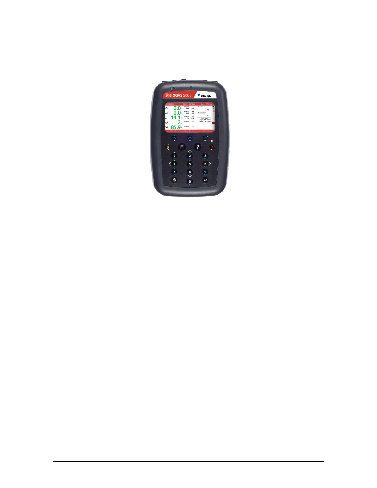
3.0 THE BIOGAS 5000 GAS ANALYZER ...................................................................9
3.1 The BIOGAS 5000.........................................................................................9
3.2 BIOGAS 5000 standard product ....................................................................10
4.0 BIOGAS 5000 OPTIONAL PRODUCTS AND ACCESSORIES.............................11
4.1 Optional products ....................................................................................... 11
4.1.1 Pitot tube (optional) .............................................................................. 11
4.1.2 Orifice plate (optional) ........................................................................... 11
4.1.3 Temperature probe (optional) .................................................................11
4.1.4 Anemometer (optional) .......................................................................... 11
4.1.5 Landtec Systems Gas Analyzer Manager –LSGAM (optional)...........................12
4.1.6 Bluetooth .............................................................................................12
5.0 BIOGAS 5000 INSTRUMENT FEATURES........................................................13
5.1 Physical characteristics of the instrument panel...............................................13
5.2 Analyzer features and keys ..........................................................................14
5.3 Instrument connection points ....................................................................... 15
6.0 GENERAL OPERATIONAL INSTRUCTIONS.....................................................16
6.1 Switching the instrument on......................................................................... 16
6.1.1 Power on self-test .................................................................................... 16
6.2 Switching the instrument off......................................................................... 16
6.3 Instrument status icons ............................................................................... 17
6.4 Instrument LED power states ....................................................................... 18
6.5 Changing between parameters......................................................................18
6.6 Entering data ............................................................................................. 18
6.7 Instrument main gas read screen.................................................................. 19
6.8 Storage .....................................................................................................19
6.9 Battery/charging.........................................................................................19
6.10 Cleaning instructions ................................................................................ 20
6.11 Memory ..................................................................................................20
6.12 Warning and error codes ........................................................................... 20
7.0 OPERATOR SETTINGS ..................................................................................21
7.1 Menu key .................................................................................................. 21
7.2 Operation settings ...................................................................................... 21
7.2.1 Timers .................................................................................................22
7.2.2 Gas Check............................................................................................ 22
7.2.3 View data.............................................................................................23
7.2.4 Set alarms ........................................................................................... 24
7.2.5 Adjust flow fail ...................................................................................... 25
7.3 Device settings........................................................................................... 26
7.3.1 Date and time....................................................................................... 26
7.3.2 Bluetooth .............................................................................................28
7.3.3 Device information ................................................................................ 28
7.3.4 Diagnostics...........................................................................................29
7.4 User settings.............................................................................................. 29
7.4.1 Operating language ............................................................................... 30

BIOGAS 5000 Gas Analyzer OMBG5KN4.7.1
Page 3of 61
7.4.2 Units of measurement............................................................................31
7.4.3 ID selection ..........................................................................................32
7.4.4 Adjust backlight ....................................................................................34
7.4.5 Adjust volume ......................................................................................35
7.4.6 User Prompts........................................................................................35
7.5 Exit menu..................................................................................................35
8.0 TAKING READINGS ......................................................................................36
8.1 Preliminary checks before taking readings (best practice) .................................36
8.1.1 Creating an ID.........................................................................................37
8.2 Special actions ........................................................................................... 38
8.3.1 Configuration of the data logging option ...................................................... 39
8.3.2 Profiling option ........................................................................................ 39
8.4 Flow Devices .............................................................................................. 40
8.5 How to use an anemometer (optional) ........................................................... 40
8.6 How to use a pitot tube (optional) ................................................................. 43
8.7 Cross gas effects on chemical cells ................................................................ 44
8.8 How to use a temperature probe (optional) ....................................................45
8.9 Taking gas and flow measurement ................................................................ 46
9.0 CALIBRATION ..............................................................................................47
9.1 Calibration introduction ............................................................................... 47
9.2 Frequency of calibration –best practice .........................................................47
9.3 Calibration gases ........................................................................................ 48
9.4 Calibration set-up .......................................................................................48
9.5 Calibration equipment ................................................................................. 49
9.6 Gas analyzer ..............................................................................................50
9.7 Calibration processes –best practice .............................................................50
9.7.1 Gas Check in fresh air ............................................................................ 51
9.7.2 Calibration –mixtures 1, 2, & 3...............................................................52
9.8 Restore to factory settings ........................................................................... 53
9.9 Calibration history.......................................................................................53
9.10 Calibration summary ................................................................................ 53
10.0 PROBLEM SOLVING ...................................................................................54
10.1 Warning and error display .........................................................................54
11.0 SERVICE....................................................................................................55
12.0 WARRANTY POLICY ..................................................................................56
15.0 GLOSSARY OF TERMS ................................................................................57

OMBG5KN4.7.1 BIOGAS 5000 Gas Analyzer
Page 4of 61
1.0 Manual guidelines
1.1 Hazard warnings and safety symbols
Warning
Information in this manual that may affect the safety of users
and others is preceded by the warning symbol.
Caution - Failure to follow the correct information may result in
physical injury which in some cases could be fatal. If the
equipment is used in a manner not specified by the
manufacturer, the protection provided by the equipment may
be impaired.
General product label symbols are listed as follows:
CE conformity-The CE-
marking is the manufacturer's
statement to the EU
authorities that the product
complies with all relevant CE-
marking Directives.
If the CSA mark appears with
the indicator "US" or "NRTL" it
means that the product is
certified for the U.S. market, to
the applicable U.S. standards.
VDE mark is a symbol for
electrical, mechanical,
thermal, toxic, radiological
and other hazards.
Separate collection, handling
and disposal for waste electrical
and electronic equipment and
its components.
Electric shock warning.
Refer to operators manual.
Double insulated construction
- does not require an Earth.
Specific marking of explosion
protection (ATEX only).
II 2G
Equipment group and
category. G = gases; the type
of explosive atmosphere.
IECEx licenced mark
(IECEx only).
Fuse.
Equipment for indoor use only.
1.2 Notes
Important/useful information and instructions are shown clearly throughout the manual
in a note format. For example:
Note: For further information please contact Technical Support at (800) 968-2026 or
email landtec_support@qedenv.com

BIOGAS 5000 Gas Analyzer OMBG5KN4.7.1
Page 5of 61
2.0 Introduction
This manual explains how to use the BIOGAS 5000 portable gas analyzer. The BIOGAS
5000 is easy to use, calibrate and configure and enables consistent collection of data for
improved analysis and accurate reporting, while helping to check the digester process is
running efficiently.
The 5000 series of gas analyzers complies with Part 15 of the FCC Rules. Operation is
subject to the following two conditions:
1) This device may not cause harmful interference.
2) This device must accept any interference received, including interference that may
cause undesired operation.
2.1 Safety instructions
Warning
The 5000 series of gas analyzers can be used for measuring gases
from landfill sites and other sources as described in this manual.
The operator may be exposed to harmful gases during the use of the
instrument. Inhaling these gases may be harmful to health and in
some cases may be fatal.
It is the responsibility of the user to ensure that he/she is adequately
trained in the safety aspects of the gases being used and appropriate
procedures are followed. In particular, where hazardous gases are
being used the gas exhausted from the analyser must be piped to an
area where it is safe to discharge the gas.
Hazardous gas can also be expelled from the instrument when
purging with clean air.
The instrument has been designed to be used in explosive
atmospheres as defined by the classification. The instrument can be
configured to measure low levels of several gases, but may not be
certified for use in potentially explosive atmospheres of these gases.
It is the responsibility of the operator to determine the protection
concept and classification of equipment required for a particular
application and whether these gases create a potentially explosive
atmosphere.
Note:Gas analyzers are a sensitive piece of scientific equipment, and should be
treated as such. If the equipment is used in a manner not specified by the
manufacturer, the protection provided by the instrument may be impaired.
2.2 Instructions for safe use
For ATEX and IECEx the 5000 series of gas analysers are certified to Hazardous
Area Classification
II 2G Ex ib IIA T1 Gb (Ta = -10ºC to +50ºC)
It is vital instructions are followed closely. It is the responsibility of the operator to
determine the protection concept and classification required for a particular application.
(Reference European ATEX directive 2014/34/EU)
The following instructions apply to equipment covered by certificate numbers SIRA
11ATEX2197X and IECEx SIR 11.0089X:

OMBG5KN4.7.1 BIOGAS 5000 Gas Analyzer
Page 6of 61
The equipment may be used with flammable gases and vapors with apparatus
group IIA and temperature class T1.
The equipment can contain gas sensing heads for the detection of particular
gases. The inclusion of a sensor does not infer that the equipment is suitable for
the use of gases with a temperature class of less than T1.
The equipment is only certified for use in ambient temperatures in the range -
10ºC to +50ºC and should not be used outside this range.
The equipment must not be used in an atmosphere of greater than 21% oxygen.
Repair of this equipment shall be carried out in accordance with the applicable
code of practice.
When used in a hazardous area only use GF5.2 temperature probe (SIRA
11ATEX2197X and IECEx SIR11.0089X). For connector C, the GF5.4 anemometer
(BVS 04ATEXE194) for use with ATEX only. The analyser should not be connected
to any other devices in the hazardous area including the GF-USB lead (connector
A) or GF3.9 battery charger (connector B) supplied with the analyzer.
Do not charge, recharge or open in a potentially explosive atmosphere.
In hazardous area only use “Temperature Probe GF5.2” in Connector B.
Connector C (Uo=10V,lo=5mA,Po=50mW,Ci=0,Li=0,Co=100uF,Lo=1000mH),
Connector B (Uo=5V,lo=6mA,Po=7mW,Ci=0,Li=0,Co=100uF,Lo=1000mH)
MAXIMUM NON-HAZARDOUS SUPPLIES:
Connector A - Um=6V Connector B - Um=10.1V
The safe area apparatus that is to be connected to the USB Port shall be a Safety
Extra Low Voltage (SELV) or Protective Extra Low Voltage (PELV) circuit.
Only a Landtec Instrument battery pack part number 20087 or 2011113 is
permitted as a replacement. This battery pack is non-field-replaceable and shall
only be changed in a safe area by QED personnel or authorized distributors.
Only Battery Charger type GF3.9 shall be used to recharge the batteries via
Connector ‘B’.
If the equipment is likely to come into contact with aggressive substances, e.g.
acidic liquids or gases that may attack metals, or solvents that may affect
polymeric materials, then it is the responsibility of the user to take suitable
precautions, e.g. regular checks as part of routine inspections or establishing
from the material’s data sheet that it is resistant to specific chemicals that
prevent it from being adversely affected, thus ensuring that the type of
protection is not compromised.
The relative pressure range is +/-500 mbar. Note, however, that the input
pressure should not exceed +/- 500 mbar relative to atmospheric pressure and
the output pressure should not exceed +/- 100 mbar relative to atmospheric
pressure.
For CSA (Canada) the 5000 series of gas analysers are certified to Hazardous
Area Classification
CLASS 2258 03 - PROCESS CONTROL EQUIPMENT - Intrinsically Safe and Non-
Incendive Systems - For Hazardous Locations

BIOGAS 5000 Gas Analyzer OMBG5KN4.7.1
Page 7of 61
Ex ib IIA:
Model GA 5000, GEM 5000 and BIOGAS 5000 Methane Detectors; portable, battery
powered with non-field-replaceable Battery Pack P/N 20087 or 2011113; intrinsically
safe and providing intrinsically safe circuits (“[ib]” for Zone 1) to Model GF5.2
Temperature Probe (Connector B) and with entity output parameters as tabulated
below; Temperature Code T1; -10 ºC Tamb. +50ºC.
Connector
Entity Parameters
Uo
(V)
Io
(mA)
Po
(mW)
Co
(uF)
Lo
(mH)
Ci
(uF)
Li
(mH)
B
5.0
6
7
100
1000
0
0
C
10.0
5
50
100
1000
0
0
Note: This device has been investigated for electrical safety features only.
For CSA (USA) the 5000 series of gas analyzers are certified to Hazardous
Area Classification
CLASS 2258 83 - PROCESS CONTROL EQUIPMENT - Intrinsically Safe and Non-
Incendive Systems –For Hazardous Locations - CERTIFIED TO U.S. STANDARDS
AEx ib IIA:
Model GA 5000, GEM 5000 and BIOGAS 5000 Methane Detectors; portable, battery
powered with non-field-replaceable Battery Pack P/N 20087 or 2011113; intrinsically
safe and providing intrinsically safe circuits (“[ib]” for Zone 1) to Model GF5.2
Temperature Probe (Connector B) and with entity output parameters as tabulated
below; Temperature Code T1; -10 ºC Tamb. +50ºC.
Connector
Entity Parameters
Uo
(V)
Io
(mA)
Po
(mW)
Co
(uF)
Lo
(mH)
Ci
(uF)
Li
(mH)
B
5.0
6
7
100
1000
0
0
C
10.0
5
50
100
1000
0
0
Note: This device has been investigated for electrical safety features only.
2.3 MCERTS
MCERTS is the UK Environment Agency's Monitoring Certification Scheme. The scheme
provides a framework within which environmental measurements can be made in
accordance with the Agency's quality requirements. The scheme covers a range of
monitoring, sampling and inspection activities.
The BIOGAS 5000 instrument is MCERTS certified only if:
The MCERTS logo appears on the screen after initial power on.
Note: MCERTS - Cross sensitivity tests using hydrogen sulphide were not carried
out on this instrument. Therefore, users should be aware if H2S is present
on sites, as there may be an interferential effect.

OMBG5KN4.7.1 BIOGAS 5000 Gas Analyzer
Page 8of 61
MCERTS promotes public confidence in monitoring data and provides industry with a
proven framework for choosing monitoring systems and services that meet the
Environment Agency's performance requirements.
The Environment Agency has established its Monitoring Certification Scheme (MCERTS)
to deliver quality environmental measurements. The MCERTS product certification
scheme provides for the certification of products according to Environment Agency
performance standards, based on relevant CEN, ISO and national standards.
MCERTS certified instruments have been tested by an independent body to ensure that
they meet certain performance requirements. In addition the manufacturer of an
MCERTS product is regularly audited to ensure that the performance requirements of the
certification are being continually met.
The 5000 series of gas analysers have been certified to Version 3.1 of the ‘Performance
Standards for Portable Emission Monitoring Systems’.
2.4 CIRIA
The CIRIA guideline ‘Assessing the risks posed by hazardous ground gases to buildings’
proposes that gas concentrations and flow rates should be monitored.
As an example methodology, they suggest using a gas analyser to first measure flow
and pressure and then afterwards to measure gas concentration.
The logging profile option offers frequency of data to be collected within a timed period
which, in return, identifies a gas profile of the sample point being monitored, information
about whether the sample point is performing correctly, when the peaks occur and
whether air is drawn in after a certain period. This logging option is available on
firmware software version 1.6.5
Versions of the GA5000 analyzer range with internal flow on firmware version 1.6.5 and
above have the ability to take measurements according to the CIRIA guidelines, while
still allowing other users to take the measurements as before.

BIOGAS 5000 Gas Analyzer OMBG5KN4.7.1
Page 9of 61
3.0 The BIOGAS 5000 Gas Analyzer
3.1 The BIOGAS 5000
The BIOGAS 5000 gas analyzer is designed for anaerobic digestion.
Benefits:
Enables consistent collection of data for improved analysis and accurate reporting.
No need for self-certification of anemometer.
Easy to use and calibrate.
User configurable operation.
Helps check digester process is running efficiently.
Features:
ATEX, IECEx certified.
MCERTS certified.
Robust design for market leading reliability.
CH4and CO2accuracy ±0.5% after calibration.
Measures % CH4, CO2and O2.
H2S to 0-500ppm or 10,000ppm.
Modular and upgradeable.
3 year warranty.
Stores and downloads readings.
User selectable languages.
Data logging.
Up to 6 gases monitored.
Applications:
Farm digester gas monitoring.
Food processing biogas monitoring.
Waste water biogas monitoring.
Methane recovery.

OMBG5KN4.7.1 BIOGAS 5000 Gas Analyzer
Page 10 of 61
3.2 BIOGAS 5000 standard product
Reference:
A
Hard carry case
B
In-line water trap tubing & filter
C
Gas analyzer instrument
D
H2S filter (optional –if the compensated CO cell is fitted)
E
Safety booklet
F
Mains battery charger and adaptors:
-UK
-Europe
-US
-Australia

BIOGAS 5000 Gas Analyzer OMBG5KN4.7.1
Page 11 of 61
4.0 BIOGAS 5000 Optional Products and Accessories
4.1 Optional products
The BIOGAS 5000 gas analyzer has a number of optional products for purchase which
enhance the usability and enable further analysis of data and reading information.
Note: For more information on the features listed in this section please contact Sales
4.1.1 Pitot tube (optional)
The BIOGAS 5000 gas analyzer enables the use of a pitot tube to aid accurate flow
measurement. The pitot tube is used for gas extraction systems and the pressure
readings are taken in mbar. High gas flow is calculated in the analyzer in m3/hr
(metres cubed per hour).
4.1.2 Orifice plate (optional)
Landtec recommends the use of orifice plates as good practice when using the BIOGAS
5000 gas analyzer, enabling repeatability in flow measurement via a fixed method.
4.1.3 Temperature probe (optional)
The BIOGAS 5000 gas analyzer has the facility to automatically display and record the
borehole temperature via an optional temperature probe.
When a temperature probe is fitted the temperature reading will be displayed on the
‘Main Gas Read Screen’ and recorded with all other data.
Note: Temperature probes with an Ex label are part of the BIOGAS 5000 Ex
certification SIRA 11ATEX2197X and IECEx SIR11.0089X, and therefore
certified for use under the same conditions as the analyzer.
4.1.4 Anemometer (optional)
The BIOGAS 5000 gas analyzer has the facility to automatically display and record high
flow via an optional anemometer probe. It is designed to plug into the instrument and
instantly provide a flow indication. An anemometer probe adds flow measurements to
the professional reporting ability of the BIOGAS 5000 range along with gas
concentrations, pressure and temperature.
The anemometer has a simple connection, a narrow diameter measurement head
(11mm), a wide temperature operating range (up to 80oC) and indicates flows up to 40
m/sec.
When an anemometer probe is fitted to the analyzer the flow will be displayed in the
‘Main Gas Read Screen’ and recorded with all other data.
Flow can be measured in either m/s (gas velocity) or m3/hr (volume flow rate). In
order to calculate the volume flow rate the pipe diameter will need to be entered into
the instrument, either manually or via the Gas Analyzer Manager software.
Note: The anemometer probe is ATEX certified for use in a potentially explosive
atmosphere under Ex certificate BVS 04ATEXE194.

OMBG5KN4.7.1 BIOGAS 5000 Gas Analyzer
Page 12 of 61
4.1.5 Landtec Systems Gas Analyzer Manager –LSGAM (optional)
Landtec Systems Gas Analyzer Manager (LSGAM) enables the operator to maximise the
operation of the gas analyzer. It enables direct communication with the unit, features a
simple upload and download facility and is fully compatible with the latest Microsoft™
operating systems.
Features:
Organization and transfer of borehole IDs and readings to and from the gas
analyzer.
Configuration of the gas analyzer.
Flexible grouping of the IDs.
Structured organisation of transferred data.
Automatic detection of instrument type and available options.
Secure data mode to prevent tampering.
First time set-up wizard.
Enable flow measurements for BIOGAS 5000 gas analyzers.
4.1.6 Bluetooth
The analyzers are fitted with a Bluetooth receiver which enables the operator to
download readings and upload IDs without the need to connect the analyzer to a PC via
a USB lead.

BIOGAS 5000 Gas Analyzer OMBG5KN4.7.1
Page 13 of 61
5.0 BIOGAS 5000 Instrument Features
5.1 Physical characteristics of the instrument panel
Front view: Reference:
Back view: Reference:
A
Main Gas Read Screen
B
Soft-keys
C
Backlight key
D
Menu key
E
Key 2 –Page Up
F
Pump key
G
LED light
H
I
On/Off key
Assistance key
J
Key 8 –Page down
K
Enter key
L
Key 0 –Space key
M
Model number
N
Serial Number
O
P
Q
Part Number
Certificate Number
Recalibrated Date
A
B
C
D
E
F
G
H
I
J
K
L

OMBG5KN4.7.1 BIOGAS 5000 Gas Analyzer
Page 14 of 61
5.2 Analyzer features and keys
Ref
Feature
Function
A
Main Gas Read Screen
Start and end screen when using the instrument.
B
Soft-keys
The function of the three ‘soft-keys’ on the front of
the instrument panel is determined by menu
options taken. Functions vary from screen to
screen.
C
Backlight key
Enables the operator to turn the backlight on/off
on the analyzer display panel.
D
Menu key
Press the ‘Menu’ key to view and maintain User,
Device and Operation settings.
E
Key 2 –Page Up
Also ‘Key 2’. Press scroll up to view further
information on the instrument screen.
F
Pump key
Press the ‘Pump’ key to start or stop the pump.
G
LED light
LED power light is visible on the front of the
analyzer when the instrument is powered on.
H
On/Off key
Press and hold the ‘On/Off’ key for 2 seconds to
switch the instrument on and off.
I
Assistance key
Press the ‘Assistance’ key to view help text
relevant to the analyzer screen you are currently
displaying.
J
Key 8 –Page down
Also ‘Key 8’. Press to scroll down to view further
information on the instrument screen.
K
Enter key
Use to accept changes, options, user inputted
answers etc.
L
Key 0 –Space key
Also ‘Key 0’. Press to enter a space when entering
text on the instrument screen.
M
Model Number
Instrument model type identification.
N
Serial Number
Unique identification for the instrument.
Verification of the serial number will be required if
Technical Support assistance is needed.
O
Part Number
Manufacturer’s part number.
P
Certification Number
Displays instrument certificate information.
Q
Recalibrated Date
The date displayed is the date the instrument is
due to be calibrated.

BIOGAS 5000 Gas Analyzer OMBG5KN4.7.1
Page 15 of 61
5.3 Instrument connection points
Top view:
Ref:
Connection Point:
Function:
A
Connector A
Attach the USB lead for PC-to-analyzer
connectivity.
B
Inlet Port & Static Pressure Port
(White port)
Attach the sample tube to take a gas sample.
Also used to measure the static pressure.
C
Differential Pressure Port
(Blue port)
Attach the sample tube to measure
differential pressure.
D
Connector B
Attach the temperature probe and also used
to attach the mains charger to the analyzer
for charging.
E
Gas Outlet Port
(Yellow port)
The gas outlet port is the point at which the
sample gas is expelled. Tubing may also be
attached to the port.
F
Connector C
Attach the anemometer.

OMBG5KN4.7.1 BIOGAS 5000 Gas Analyzer
Page 16 of 61
6.0 General Operational Instructions
6.1 Switching the instrument on
1) To switch on the analyzer, press and hold the ‘On/Off’ key. The Landtec logo will
display followed by the instrument warm up.
2) Following the instrument warm up, the ‘Date and Time’ screen is displayed
prompting the technician to set the date and time and required format.
3) When complete select the soft-key to ‘Exit’ and the ‘Power On Self-test’ screen is
displayed followed by instrument status. Instrument status displays the
instruments service due date, serial number, options, service scheme and software
version. Text will also display stating ‘Self-test complete’.
4) When complete the instrument will display the ‘Main Gas Read Screen’.
6.1.1 Power on self-test
When switched on, the read-out will perform a pre-determined self-test sequence.
During this time many of the analyzer’s functions are tested, including:
General operation
Gas flow measurement
Calibration
Battery charge level
During the self-test the following information is also displayed:
Manufacturer’s service due date
The last gas check date
Software version programmed
Date format
Serial number
Operating language
The currently enabled sales option
Note: The self-test should only be done with the analyzer sampling fresh air.
6.2 Switching the instrument off
1) To switch off the analyzer, press and hold the ‘On/Off’ key, at which point a clean
air purge will be carried out and the instrument will then switch off.
2) If for any reason the analyzer ‘locks up’ and will not switch off in this manner,
press and hold the ‘On/Off’ key for 15 seconds; this will force the instrument to
switch off.

BIOGAS 5000 Gas Analyzer OMBG5KN4.7.1
Page 17 of 61
6.3 Instrument status icons
The following icons may be displayed on the instrument screen:
Icon
Description
Icon
Description
Battery charge state
Gives the operator an
estimation of the battery
charge state. For example
100% gives about 8 hours
use in the field and 50%
would mean that there is
approximately 4 hours
battery life remaining.
Battery charge state
Indicates less than 2 hour of charge
remaining.
Pump status
This icon is displayed
along with a counter
showing the pump run-
time. This counts down
where the operator has
specified the pump run-
time; if not it counts up;
the icon turns red when
stalled.
Pump stalled
This icon is displayed when the pump
stalls. The instrument’s gas inlet (or
outlet) may be blocked. This warning is
most commonly caused by a water-
logged or dirty sample filter. Change the
sample filter and check for obvious
blockages in the sample tubes.
Alternatively, a small amount of
adjustment can be made to the low flow
detection point to compensate for minor
changes in the performance of the pump
fitted to the instrument.
GPS signal strength
This icon shows the signal
strength the analyzer’s
GPS module is able to
provide. Full, okay and fair
strength respectively.
GPS failure
The GPS was unable to get a line of sight
lock on enough satellites. Or, it may be
that it hasn’t had time to get a lock.
This indicates when
Bluetooth has been
enabled.
Language
This icon indicates the currently selected
operating language. This can be changed
via the main menu.
Data logging
This icon indicates that the
data logging feature is in
operation.
Service overdue
This icon indicates that the analyzer is
overdue for its service
Legacy mode
This icon indicates that the
analyser is in legacy mode
and hence is ready to
connect to a PC.
USB disabled
This icon indicates that the analyser has
reached a battery critical state, and
hence has turned off its USB
connectivity.

OMBG5KN4.7.1 BIOGAS 5000 Gas Analyzer
Page 18 of 61
6.4 Instrument LED power states
When the instrument is powered on a LED power light is visible on the front of the
analyser, located above the ‘On/Off key’. The following LED power light states are as
follows:
Steady yellow
Unit turning on. This will extinguish when software has loaded
correctly.
Flashing (rapid)
Unit is powering off.
Flashing (slow)
Power off is being delayed for purge/shutdown handling.
Flashing yellow
Unit is turning off due to power button being pressed.
Flashing red
Unit is turning off due to critically low battery.
Note: Pressing and holding the power button for ~20s resets the analyser.
6.5 Changing between parameters
By default, the instrument displays the ‘Main Gas Read Screen’ (for gas measurement).
The instrument will return to this screen after power on or when returning from the
menus. The ‘Scroll’ keys can be used to switch to another measurement screen.
6.6 Entering data
During normal operation the operator may be prompted to enter data or information via
the keypad, i.e. entering an ID code or setting an alarm level.
When entering data into the instrument all fields are fixed format and are populated
from the left.
Text:
Entering text uses similar multi-tap functionality as a mobile phone. Key the
numeric/alpha key pad the required number of times to select the appropriate letter. To
key numeric data continue to press the numeric/alpha key until the required number is
displayed.
Numeric data:
To enter a new date 09/15/16 the operator would type in 091516 using the numeric
keypad in the following sequence:-
* 0_/__/__
* 09/__/__
* 09/1_/__
* 09/15/__
* 09/15/1_
* 09/15/16
Press the ‘Enter’ key to confirm/accept data keyed.
Any mistakes can be corrected using the soft-key ‘Delete’ which will delete the last digit
typed. Alternatively, the sequence can be retyped before the ‘Enter’ key is pressed and
the existing numbers will be pushed off the screen.
Note: The instrument will not allow invalid data to be entered; this should be deleted
and re-entered.

BIOGAS 5000 Gas Analyzer OMBG5KN4.7.1
Page 19 of 61
6.7 Instrument main gas read screen
The ‘Main Gas Read Screen’ is considered to be the normal operating screen and all
operations are carried out from this starting point.
The actual data shown on this display will depend on the version of the instrument and
the options that have been selected. In general, all of the main readings will be shown.
Main Gas Read Screen
6.8 Storage
The analyzer should not be exposed to extreme temperature. For example, do not keep
the analyzer in a hot car. When not in use, analyzers should be kept in a clean, dry and
warm environment, such as an office. Protect the analyzer with either the soft carry case
or store in the hard carry case provided with the instrument.
The instrument should be discharged and fully charged at least once every four weeks,
regardless of indicated charge state.
6.9 Battery/charging
The battery used in the 5000 series of gas analyzers is nickel metal hydride and
manufactured as a pack from six individual cells. This type of battery is not so
susceptible to the top-off charging ‘memory effects’ as nickel cadmium batteries,
although it is not recommended that the unit is given small top-off charges.
Note: To reach optimum charge, it is recommended that the instrument is
switched off when being charged and remains switched off during
the charging process.
A full charge will take approximately 4 hours from a fully discharged battery.
Warning
The battery charger is NOT covered by the Ex certification.
The battery must be charged only in a safe area.
The battery charger is intelligent and will indicate when the unit is charging and charged.
The instrument must be charged ONLY using the battery charger supplied with the
instrument. The battery charger supplied is intended for indoor use only. Please ensure
adequate ventilation while charging. Typically, a fully charged battery will last 7-8 hours.
A quick 30 minute charge can be used to give approximately one hours use in the field
but this may shorten the battery life. Temperature can dramatically affect the battery
life; please take this into account when estimating battery life.
Note: Connect the charger to the mains attaching the appropriate adaptor.

OMBG5KN4.7.1 BIOGAS 5000 Gas Analyzer
Page 20 of 61
Power supply front and back drawing:
Charger: Input voltage: 100-240V AC +/- 10%
Input frequency: 50-60Hz +/- 10%
Input current: 0.4A@100VAC .. 0.2A@240VAC
Output voltage: 10.1VDC max
Output current: 1.5A max
Note: This charger has been internally restricted to 1.5A
6.10 Cleaning instructions
Do NOT use any cleaning agents to clean the analyzer or battery charger as they may
have an adverse effect on the safe use of these devices.
6.11 Memory
The analyzer's memory is stored in a readings and configuration database. The analyzer
will prompt when its memory is full, and you will not be able to store any further
readings. Please download your readings via LSGAM or the Basic Download Software and
then clear the memory.
Note: The analyzer should never be stored for prolonged periods with valuable data
in its memory. It is advisable to download all readings to LSGAM at the end
of each day’s monitoring. To clear the memory, please refer to the LSGAM
operating manual.
6.12 Warning and error codes
When switched on, the instrument will perform a predetermined self-test sequence
taking approximately ten seconds. During this time many of the instrument’s working
parameters and settings are checked. If any operational parameters are out of
specification or if the pre-programmed recommended calibration/service date has
passed, errors or warnings may be displayed.
Note: For further information please refer to section ‘10.0 Problem Solving’.
Table of contents
Other LANDTEC Measuring Instrument manuals