Open-Q™ 660 µSOM Dev Kit User Guide 4
3.7.20 Audio Headset Jack J1800 (8) ______________________________________41
3.7.21 WLAN / BT Antenna Connections ___________________________________41
3.7.22 Quiet Thermistor RT800 (35) _______________________________________42
3.7.23 Haptic Output Header J802 (10) ____________________________________43
List of Figures
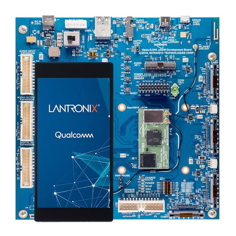
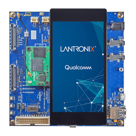
Figure 1. Assembled Open-Q 660 µSOM Development Kit................................................................. 11
Figure 2. Open-Q 660 µSOM Dev Kit Block Diagram .......................................................................... 14
Figure 3. DIP switch assignments ........................................................................................................ 18
Figure 4. Power source selector switch S300 (2)................................................................................. 19
Figure 5. Battery ID and Thermistor DIP Switch S301 (4) ................................................................... 20
Figure 6. J400 12V DC Power Jack (1)................................................................................................ 20
Figure 7. Battery Connector J300 (3) ................................................................................................... 21
Figure 8. SOM Current Sense Header J301 (5)................................................................................... 22
Figure 9. Coin Cell Battery Holder B300 .............................................................................................. 23
Figure 10. Power Header J700 (36) ..................................................................................................... 23
Figure 11. Debug UART over USB J1600............................................................................................ 25
Figure 12. USB Type C (for ADB) J2300 ............................................................................................. 26
Figure 13. USB 2.0 Type A Connector J2400 (6)................................................................................. 26
Figure 14. Micro SD Card Socket J1500.............................................................................................. 27
Figure 15. Display Connector J1300 .................................................................................................... 28
Figure 16. Typical Camera Connector ................................................................................................. 30
Figure 17. Camera Flash/Torch Connectors J1001 (18) and J1201 (19) ............................................ 31
Figure 18. Digital IO Expansion header J2200..................................................................................... 32
Figure 19. Sensor Expansion Header J2100 ....................................................................................... 34
Figure 20. Audio Inputs Expansion Header J1900 (33) ....................................................................... 35
Figure 21. Audio Outputs Expansion Header J1901 (32) .................................................................... 37
Figure 22. Audio IO Expansion Headers 1 and 2, J2000 and J2001 ................................................... 38
Figure 23. Audio Headset Jack J1800 (8) ............................................................................................ 41
Figure 24. WLAN / BT SOM Connections (21, 22)............................................................................... 41
Figure 25. Channel 0 and 1 WLAN/BT routing and PCB Antennas on Carrier Board ......................... 42
Figure 26. Quiet Thermistor RT800 Location (34)................................................................................ 43
Figure 27. Haptic Output Header J802 (10) ......................................................................................... 43
List of Tables
Table 1. List of Development Kit Features itemized in the figure above .............................................. 12
Table 2. Carrier Board Features........................................................................................................... 16
Table 3 - System Configuration DIP Switch Settings ........................................................................... 18
Table 4. Battery Connector J300 Pinout .............................................................................................. 21
Table 5 - Power Header J301 Pinout ................................................................................................... 22
Table 6. Power Header J700 (36) ........................................................................................................ 24
