Lantronix xPico User manual

Part Number 900-623
Revision D January 2018
xPico Development Kit
Quick Start Guide

xPico Development Kit Quick Start Guide 2
Intellectual Property
© 2018 Lantronix, Inc. All rights reserved. No part of the contents of this
publication may be transmitted or reproduced in any form or by any means
without the written permission of Lantronix.
Lantronix and DeviceLinx are registered trademarks of Lantronix, Inc. xPico and
DeviceInstaller are trademarks of Lantronix, Inc.
Patented: http://patents.lantronix.com; additional patents pending.
UNIX is a registered trademark of The Open Group. Windows is a trademark of
Microsoft Corporation. All other trademarks and trade names are the property of
their respective holders.
Warranty
For details on the Lantronix warranty replacement policy, please go to our Web
site at www.lantronix.com/support/warranty.
Contacts
Lantronix, Inc.
7535 Irvine Center Drive
Suite 100
Irvine, CA 92618, USA
Toll Free: 800-526-8766
Phone:949-453-3990
Fax: 949-453-3995
Technical Support Online: www.lantronix.com/support
Sales Offices
For a current list of our domestic and international sales offices, go to the
Lantronix web site at www.lantronix.com/about/contact.
Revision History
Date
Rev.
Comments
April 2012
A
Initial release.
August 2012
B
Updated for the new revision of the evaluation board.
March 2013
C
Updated for the new xPico Modbus module.
January 2018
D
Updated enhanced password information.

xPico Development Kit Quick Start Guide 3
Table of Contents
Table of Contents_______________________________________________________ 3
Introduction ___________________________________________________________ 4
Development Kit Contents ________________________________________________ 4
What You Need to Know _________________________________________________ 4
Hardware Address ___________________________________________________ 4
IP Address _________________________________________________________ 4
Connecting an xPico Module — Network Method ______________________________ 5
Connecting an xPico Module — Serial Method ________________________________ 6
Install DeviceInstaller ____________________________________________________ 6
Assign an IP Address____________________________________________________ 7
Configure Your xPico Device ______________________________________________ 9
xPico Module _______________________________________________________ 9
xPico-IAP Module____________________________________________________ 9

xPico Development Kit Quick Start Guide 4
Introduction
Thank you for purchasing the xPico Development Kit from Lantronix.
This Quick Start guide describes the procedures for initial connection to the xPico
module through either a network connection or serial port.
Once a connection is established you can use the WebManager or Setup Mode
for configuration and control.
Development Kit Contents
Note: The xPico Evaluation Board is designed to work with the family of xPico
serial to Ethernet modules. Please ensure that you have the correct module for
your needs. The Evaluation Kit comes with the standard xPico serial to Ethernet
device. If you wish to use the xPico-IAP then please ensure that you have the
XPC10010MS-01 or later module.
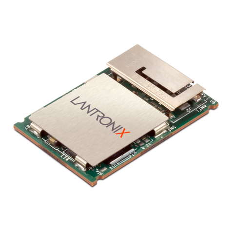
♦xPico Module
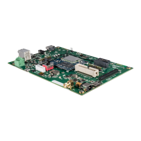
♦xPico Evaluation Board
♦Two xPico Mounting Quick Clips (one installed)
♦Sample 40-pin Mating Connector
♦5V Wall-mount Power Supply AC/DC, 1A
♦RS-232, DB9F/F, 10 ft, Null Modem Cable
♦Ethernet Cable 10 ft
For the latest revision of this product document, please check our online
documentation at www.lantronix.com/support/documentation.
What You Need to Know
Hardware Address
You need to know the unit hardware address (also known as MAC address) to
identify the unit in the Device Installer search list. It is on the product label in the
format: 00-80-A3-XX-XX-XX, where the XXs are unique numbers assigned to
the product.
Hardware Address: 00-80-A3-_____-_____-_____
IP Address
Your xPico will need a unique IP address on your network. By default, the xPico
module is assigned an IP address by your DHCP server. If no DHCP server is
available, the xPico will generate an AutoIP address (169.254.xxx.xxx).
If you are planning to use a static IP address, make note of it. The system
administrator generally provides the IP address, subnet mask, and gateway. The
IP address must be within a valid range, unique to your network, and in the same
subnet as your PC.

xPico Development Kit Quick Start Guide 5
IP Address: _______ _______ _______ _______
Subnet Mask: _______ _______ _______ _______
Gateway: _______ _______ _______ _______
Connecting an xPico Module — Network Method
A network connection, if the equipment is available, is the preferred method for
the initial configuration of the xPico.
Note: Before wiring and powering on the xPico Evaluation Board please make
sure that the correct xPico module for your needs is fitted. Removing and
inserting the xPico module is quite simple and requires removing the fitted
mounting clip and exchanging the module in the 40-pin socket.
1. Connect the PC to the Evaluation Board with a cross-over cable or a
hub/switch and two RJ45 cables. Make sure there is no router between the
PC and the Evaluation Board.
2. Select the appropriate power plug adaptor for your geographical location.
Insert it into the slot on the Universal Power Supply; then plug the power
supply into an outlet.
3. Connect the output plug of the power supply to the Evaluation Board.
4. Move the power switch on the Evaluation Board to ON.
This is the last step in 'connection.' The xPico is ready for configuration.
5. Continue with Install DeviceInstaller on page 6.

xPico Development Kit Quick Start Guide 6
Connecting an xPico Module — Serial Method
In the event that the equipment required for a network connection is not available
for the initial configuration of the xPico, the serial method can be used.
1. Connect one end of the supplied DB9F/F serial cable to the serial port on the
laptop or desktop.
2. Connect the other end of the supplied DB9F/F serial cable to Port 1 on the
xPico Evaluation Board.
3. Select the appropriate power plug adaptor for your geographical location.
Insert it into the slot on the Universal Power Supply; then plug the power
supply into an outlet.
4. Connect the output plug of the power supply to the xPico Evaluation Board.
The final serial connection setup should look like this:
5. Move the power switch on the Evaluation Board to ON.
This is the last step in 'connection.' The xPico is ready for configuration.
6. Continue with the Install DeviceInstaller section below.
Install DeviceInstaller
Use DeviceInstaller to configure the IP address and other network parameters.
Note: You will need a Windows PC running Lantronix DeviceInstaller 4.3.0.5 or
higher.
1. Download the latest version of DeviceInstaller from
www.lantronix.com/downloads.
2. Run the executable to start the installation process.
3. Respond to the installation wizard prompts. (If prompted to select an
installation type, select Typical.)

xPico Development Kit Quick Start Guide 7
Note: For more information about DeviceInstaller, see the DeviceInstaller Online
Help.
Assign an IP Address
The unit IP address is set for DHCP by default at the factory. The hardware
address is on the product label. Assign a static IP address if you do not want the
network to assign an IP address to the xPico or do not have a DHCP server on
the network.
1. Click StartPrograms LantronixDeviceInstaller 4.4
DeviceInstaller. If your PC has more than one network adapter, a
message appears. Select an adapter and click OK.
2. Click the Search icon and select the unit from the list of Lantronix device
servers on the local network. (In case no DHCP server is available, it can
take 30 seconds before an AutoIP address is generated and the unit is
detectable).
3. Click the Assign IP icon .
4. Select Assign a specific IP address and click Next.

xPico Development Kit Quick Start Guide 8
5. Enter the IP address.
The Subnet mask appears automatically based on the IP address.
You may change it. On a local network, you can leave the Default gateway
blank (all zeros).
6. Click Next.
7. Click Assign and wait several seconds until a confirmation message
appears.
8. Click Finish.
9. Select the xPico from the main window list and click Tools
Ping. The
results appear in the Status area.
10. Click Clear Status to clear the window to ping the device again.
Note: If you do not receive “Reply” messages, ensure the IP address assigned is
valid for the particular network segment you are working with.
11. Click Close.

xPico Development Kit Quick Start Guide 9
Configure Your xPico Device
Using DeviceInstaller it is easy to configure the unit over the network.
xPico Module
From DeviceInstaller it is easy to start the Lantronix browser-based tool, “Web
Manager” to configure the xPico. For detailed information on Web Manager
configuration and on other methods, see the xPico User Guide.
1. In DeviceInstaller, select the unit and then the Web Configuration tab. Click
the Go icon. The Lantronix Web Manager login window appears.
2. For the xPico, there is no default user name or password.
Note: We recommend that you always use the enhanced password setting
and create a strong 16 character password through Telnet or serial
connections. See the xPico Embedded Device Server User Guide available
at www.Lantronix.com/downloads for instructions. Using no password is very
dangerous.
3. Use the menu on the left to navigate to sub-pages where you can configure
the xPico module.
4. Commit any changes as follows:
Every sub-page has an OK button that tells the xPico what changes to
use, but it does not immediately change the configuration on the device.
When you are finished making all changes to the settings on various
pages, then click Apply Settings, which makes the changes permanent
and reboots the xPico.
xPico-IAP Module
From DeviceInstaller it is easy to start a Telnet connection to configure the unit
over the network. For detailed information on configuration, see the Modbus
Protocol User Guide.
1. In DeviceInstaller, select the unit and then the Telnet Configuration tab.
2. Click the Connect icon. The following information displays:
Lantronix Inc. - Modbus Bridge
MAC address 0080A366000D
Software version V3.3.0.0 (130306) XPICO
Press Enter for Setup Mode
3. To enter Setup Mode, press Enter within 5 seconds. The configuration
settings display, followed by the change prompt:
Select Command or parameter set (1..7) to change:
4. Select an option on the menu by entering the number of the option and
pressing Enter.

xPico Development Kit Quick Start Guide 10
5. To enter a value for a parameter, type the value and press Enter, or to
confirm a current value, just press Enter.
6. When you are finished making all changes to the various settings, use the
(S)ave option to save the new configuration by entering S. The unit
automatically reboots.

Mouser Electronics
Authorized Distributor
Click to View Pricing, Inventory, Delivery & Lifecycle Information:
Lantronix:
XPC100100K-02
Other manuals for xPico
3
Table of contents
Other Lantronix Microcontroller manuals

Lantronix
Lantronix Open-Q 660 mSOM User manual

Lantronix
Lantronix XPort 080-318 User manual

Lantronix
Lantronix Open-Q 865 User manual

Lantronix
Lantronix xPico User manual

Lantronix
Lantronix MatchPort User manual

Lantronix
Lantronix Intrinsyc Open-Q 865XR SOM User manual

Lantronix
Lantronix Open-Q 212A User manual

Lantronix
Lantronix Open-Q 410 User manual

Lantronix
Lantronix HDK845 User manual

Lantronix
Lantronix Open-Q 845 mSOM User manual