Code No.
NSDX-35 2SL
NSDX-35 2SR
Position
Left
Right
Suitable screw on stay
3.5 × 3
3.5 × 3
Suitable screw on
mounting plate
Suitable screw on
mounting plate
3.5 × 3
3.5 × 3
Code No.
NSDX-35E 2SL
NSDX-35E 2SR
Position
Left
Right
Suitable screw on stay
6.2 × 2
6.2 × 2
3.5 × 3
3.5 × 3
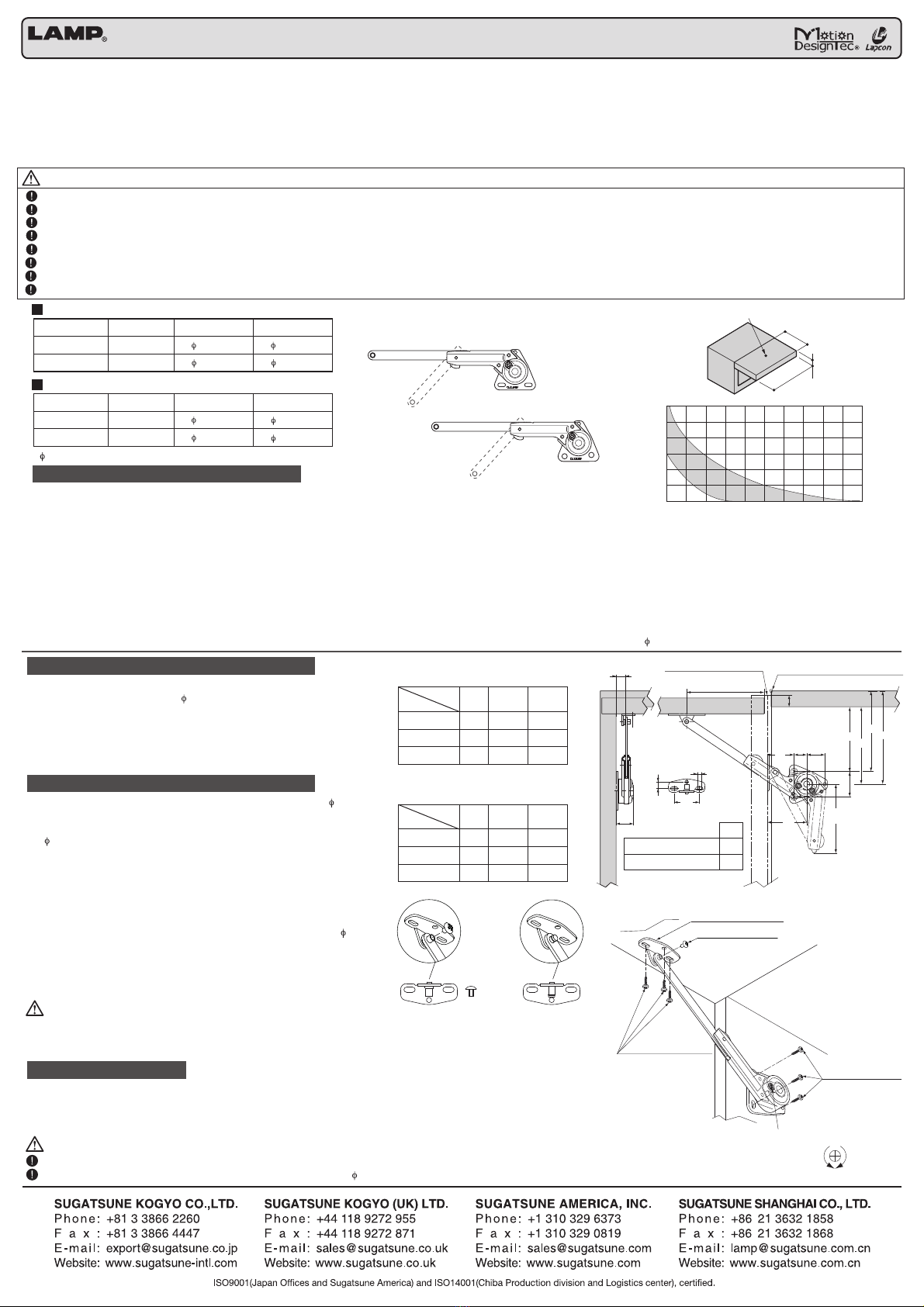
Model (For standard screw)
Model (For Euro screw)
*6.2 Euro Screw to be applied
MEASURE-
MENT
80° / 60°
90° / 65°
100° / 70°
A
106
98
92.5
B
105-S
97-S
91.5-S
C
121-S
113-S
107.5-S
OPENING
ANGLE
MEASURE-
MENT
OPENING
ANGLE
■CONCEALED HINGE
A
100
91.5
85
D
99
90.5
84
E
115
106.5
100
■PIANO HINGE OR BATT HINGE
Door height
Door thickness (20mm)
Door Width(W)
Center of gravity (Density = 0.5)
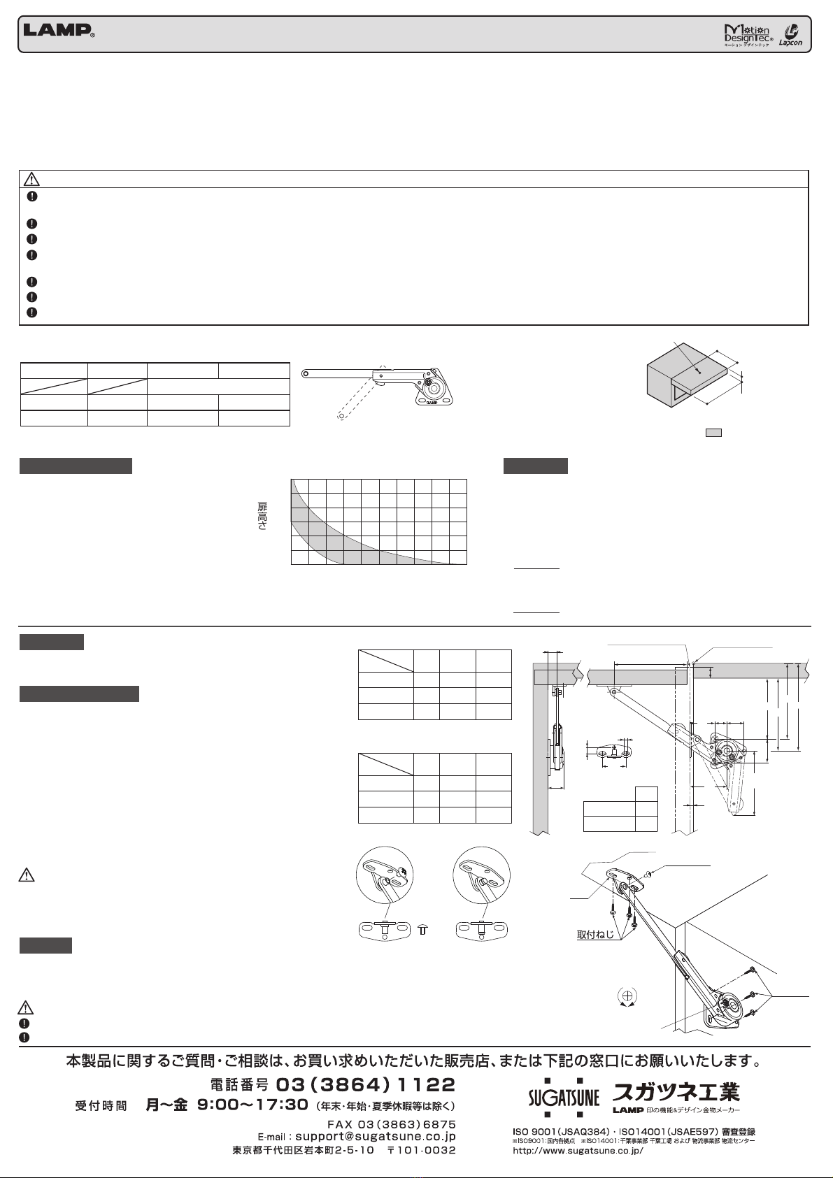
APPLICABLE DOOR WEIGHT AND SIZE
Above drawing shows for NSDX-35 2SL (left hand side mounting) and NSDX-35 2SR (Right hand side mounting) symmetrically. Same mounting
position is to be applied to the model of 35 EURO (type with EURO screw). Make a preparatory hole, Before drilling a 6.2 EURO screw.
NSDX-35 2S INSTALLATION PROCEDURE
1. Mount the body and arm fixing plate on sideboard and back of
door with tapping screws ( 3.5) to oval holes temporarily.
2. Align notch on mounting plate and hole on arm by rotating the
stays to fix them.
3. Check the function and adjust mounting plate on oval holes.
Then fix them with the tapping screws in the round holes of the
stay and mounting plate.
Mounting plates are available both in standard and clip type.
When using a standard mounting plate type, be sure to fix it securely
with supplied truss screw after installing the stay. When using a clip
mounting plate type, be sure to insert arm completely.
In using a clip mounting plate type, be careful not to hit the arm or
apply excessive force, as it may cause the arm to fall off and cause
unexpected injury.
NSDX-35E 2S INSTALLATION PROCEDURE
1. Mount the stay on sideboard by applying EURO screw ( 6.2) to
the larger round holes on the body.
2. Mount the arm fixing plate on back of door with tapping screws
( 3.5) to the oval holes temporarily.
3. Align notch on mounting plate and hole on arm by rotating the
body to fix them.
4. Check the function and adjust mounting plate on oval holes.
Then fix them with the tapping screws in the round holes of the
body and mounting plate.
*If the side board is not enough strength to support the stay,
smaller round hole of the body must fix with tapping screw( 3.5).
SPEED ADJUSTMENT
Upon completion of installation, make sure the door opens and closes properly.
To adjust the opening/closing speed of door, turn speed adjustment screw.
In case 2 units (right & left) are used on a single door, the speed adjustment screws
on both sides must be turned evenly.
This product must be applied to a door with specific weight and size. Lined Section on
the right of the graph indicates applicable door weight range based on 1 unit per door.
Note-1: In case of 2 units (right & left) per door are used
Door Width can be twice as large, if the door height remains unchanged
Note-2: In case of different door thickness or specific gravity, door weight must fit with
following formula.
*1 unit per door:
MIN
.
-
MAX
.
1/2 door height [m] ×door weight [kg] ×9.8 = 1.96 - 4.9 [N؞m] (20 ~ 50 [kgf؞cm] )
(1/2 door height [inch] ×door weight [lb]= 17 ~ 43 [lb؞inch])
*2 units (right & left) per door:
MIN
.
-
MAX
.
1/2 door height [m] ×door weight [kg] ×9.8 = 3.92 - 9.8[N؞m] (40 ~ 100 [kgf؞cm])
(1/2 door height [inch] ×door weight [lb] = 35 ~ 85 [lb؞inch])
CAUTIONS
CAUTIONS
Do not turn the speed adjustment screw exceeding the limit.
For speed adjustment, use a Philips (plus) screwdriver with 5 or less.
*In case of usual wooden flap of 20 mm thickness
(specific gravity approx. 0.5)
Door height (mm)
Door width (mm)
NSDX-35E 2S
TOP BOARD
IN CASE OF CONCEALED HINGE
IN CASE OF BUTT HINGE OR PIANO HINGE
F
SIDE BOARD
HINGE CENTER
HINGE CENTER
DOOR
B
S
50
2316
34
A
(87) 32
22
CD
E
CLIP MOUNTING PLATE
STANDARD MOUNTING PLATE 11.0
11.8
S= OVERLAY COVERAGE
BY CONCEALED HINGE
F
PAT.PPAT.PNSDX-35 2S
This item is same design as NSDX-35, and
item no. NSDX-35 2S is stamped at the back
side of body.
300
400
500
600
700
800
900
100 200 300 400 500 600 700 800 900 1000 1100
80° / 60°
90° / 65°
100° / 70°
●
Please read this instruction sheet carefully for proper installation and operation. Incorrect installation or use of this product may damage the unit or cause injury.
●
This stay is designed for furniture or lightweight door and is equipped with a damping function.
●
Sugatsune guarantees the quality of this product as for all its parts. It cannot however guarantee the final assembly as a whole.
●
This product was manufactured and delivered with our utmost care. Should you however find any defect, please contact your dealer immediately.
●
Sugatsune warrants that this product is free from defect for a period of one (1) year from the date of delivery.
●
Sugatsune liability is limited to the replacement of this product by a similar one free of defect. In no case does this extend to the replacement of the installation or the cabinet as a whole.
●
Please keep these instructions at hand for future use.
●
Sugatsune cannot be held liable for any damage or injury caused by improper use or one different than the one this product was designed for.
Make sure that installation position and specifications are followed. Unsuitable installation position may damage the mechanism when in case two stays are used together.
Make sure that the arm of the stay is parallel with the side panel of the cabinet.
Please avoid forced opening beyond the opening angle, and using excessive force while closing the door.
This product is designed to operate at room temperatures between 0˚C to 40˚C (32F-104F).
This product has a spring at the elbow section. Please be careful not to get your fingers caught in elbow section while you are handling the unit.
Performance of hardware will be affected by unique factors in each application. Hardware must be tested in intended application to confirm the function.
It is necessary to periodically check the fixing screws for loosing. Tighten the loosed screws as required.
Do not force the door to close faster. It can cause damage to the product or hinge(s) .
CAUTIONS Any failure to observe the following precautions may result in personal injury or damage to the cabinet
SOFT DOWN STAY NSDX-35 2S (with 2 stops at 65 / 90)
STANDARD MOUNTING
PLATE
CLIP MOUNTING PLATE
DOOR
SIDE
BOARD
SLOWER
FASTER
TAPPING SCREW
TAPPING SCREW
SPEED ADJUSTMENT SCREW
MOUNTING PLATE
TRUSS SCREW
32
8.5
5