3
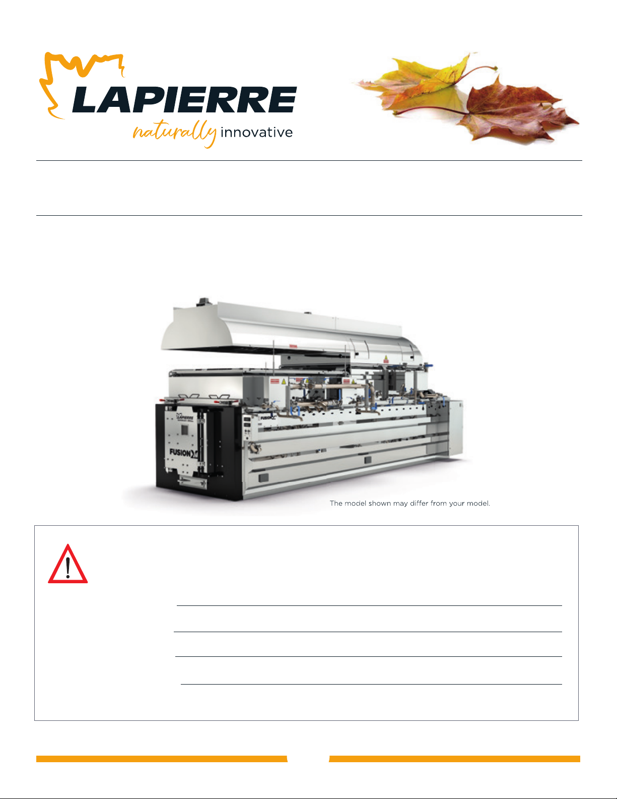
Lapierre Equipment | FUSION X
2
EVAPORATOR | USER MANUAL | Version 01 - September 2022
4. Installation and component assembly.............................................................13
4.1 Levelling the evaporator ....................................................................13
4.2 Masonry and insulation .................................................................... 14
4.3 Installing the chimney and the steam vents.................................................. 14
4.3.1 LWS listed chimney.................................................................. 14
4.3.2 Single wall chimney (non-listed) ..................................................... 14
4.3.3 Steam vents........................................................................ 14
4.4 Pan installation ............................................................................15
4.5 Connecting the draw-off components .......................................................15
5. Start-up, operation and shutdown procedures.................................................... 16
5.1 Evaporator start-up........................................................................ 16
5.1.1 Check connections for leaks and tightness ............................................. 16
5.1.2 Check for leaks and floats ............................................................ 16
5.1.3 Check the fans ...................................................................... 16
5.2 Evaporator operation.......................................................................18
5.2.1 Lighting up the combustion chamber ..................................................18
5.2.2 Syrup production ...................................................................2
0
5.2.3 Changing the syrup pan ..............................................................21
5.3 Evaporator shutdown ......................................................................21
6. Equipment maintenance and cleaning ...........................................................22
6.1 Recommended maintenance at the start of the season .......................................22
6.2 Recommended maintenance at the end of the season........................................22
6.3 Annual replacement of parts, recommendation ..............................................22
6.4 Door cleaning and maintenance............................................................23
6.5 Evaporator cleaning.......................................................................23
7. Troubleshooting kit ............................................................................24
7.1 No primary or secondary air fan operating ...................................................24
7.2 One of the primary or secondary air fans is not working ......................................24
7.3 A temperature indicator does not work .....................................................25
7.4
One or two temperature indicators show erratic values or an error message
......................25
7.5 The temperature of the combustion chamber is 1.5 times lower than that of the chimney ........26
7.6 Poor evaporator performance ..............................................................27
7.7 Solid deposits (staining) in the pans ........................................................29