8
Lapierre Equipment | SYRUP PRESS | USER MANUAL | Version 01 - December 2021
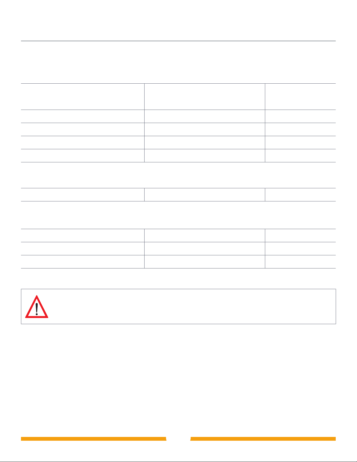
SECTION 3 Equipment installation; part descriptions and codes (continued)
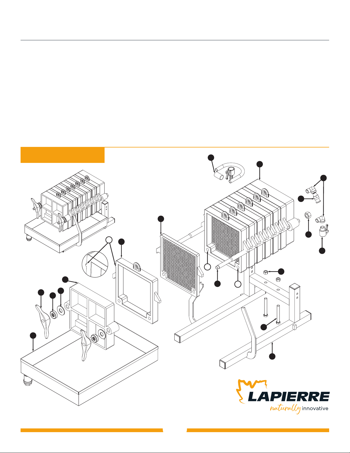
PART DESCRIPTIONS AND CODES
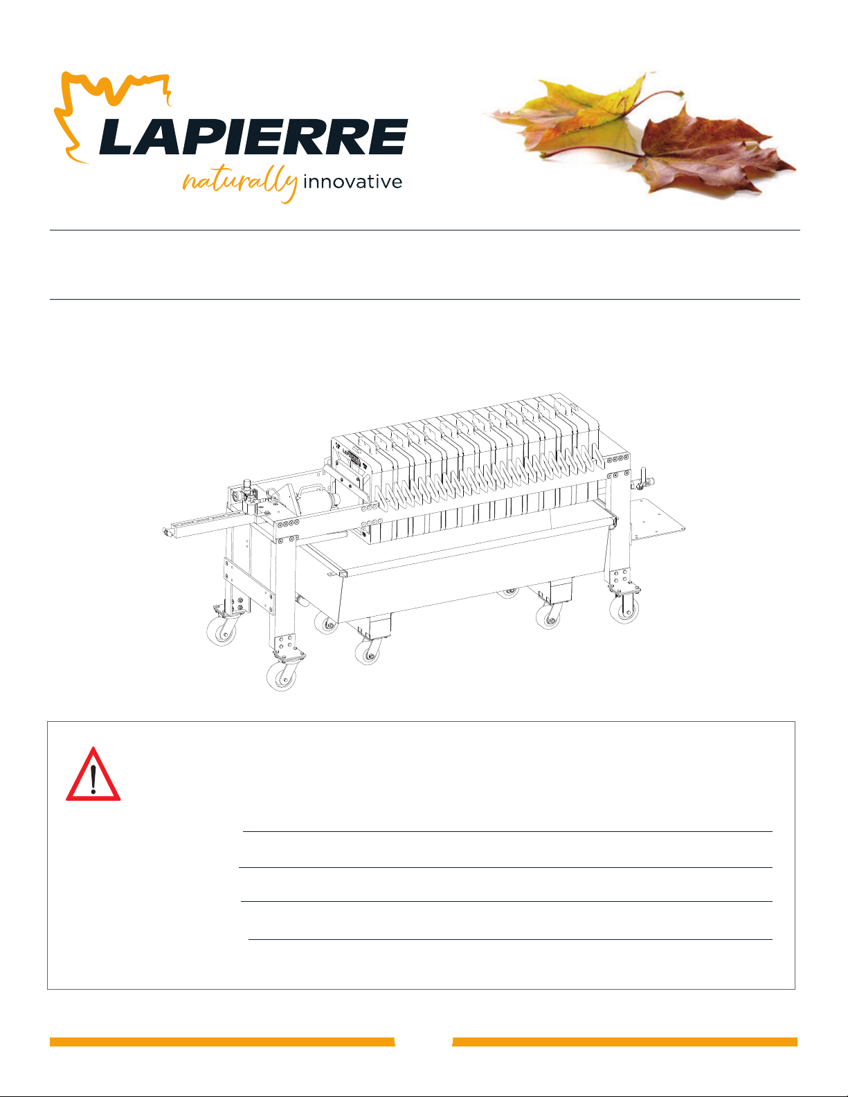
Equipment shown above: 10 inch square syrup press
Configuration shown: 7 hollow frames / 6 plates
Model number shown: SR010-070610XX
Note: Without pump unit
No
Qty
Part description
Dimensions
Part code
11 10 in. rear block, inlet and outlet, for square press 13-7/16 in. SR405-100005XX
21 Front block 10 in., closed, for square press 13-7/16 in. SR405-100009XX
36 10 in. plate for square press 12-3/4 in. SR405-100008XX
42 Shaft, for standard square press, 7 or 10 in. 23-7/8 in. SR405-000007XX
51 10 in. tilt stand with reinforcing bar for square press N/A SR405-100001XX
67 10 in. hollow frame, for square press 13-1/8 in. SR405-100007XX
72 Flat washer, zinc, inside dimension 13/16 in., for 3/4 in. bolt N/A BU200-000013K1
82 Handle, for square press N/A SR405-000011XX
92 Ball bearing 4459-00 brgs, for press and water filter N/A DV234-445900XX
10 2 Hexagonal nut, zinc, 3/4 in.-10 N/A BU207-001210K1
11 2 Bolt, hexagonal, zinc, 1/2 in.-13 x 4 in. grade 2 N/A BU202-081364K1
12 2 Hexagonal nut, zinc, 1/2 in.-13 N/A BU207-000813K1
13 2 Elbow, stainless steel, 90 degrees, 1/2 in. mpt x fpt N/A RA754-000808S6
14 1 Quick coupling, aluminium, 1/2 in., part F N/A RA785-000008A1
15 1 Quick connector, aluminium, 1/2 in., part B N/A RA781-000008A1
16 1 Clear pipe, 9/16 x 15/16 in., assembled, 6 ft. N/A SR200-000027XX
17 17 or 10 in. pan, for standard square press; including valve,
stainless steel, 3/4 in. N/A SR015-001007SS
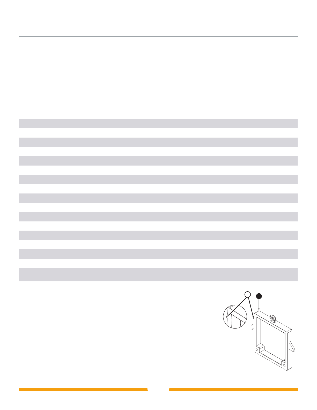
Guides for correct installation of blocks, hollow frames and plates
This protrusion (A) is found on one side of the blocks, hollow frames and plates
and forms a line along the press when the installation of these components is
complete, as shown in illustration 2.
When facing the press handles (Illustration 1 No. 8), the protrusions should be
on the left side of the press.