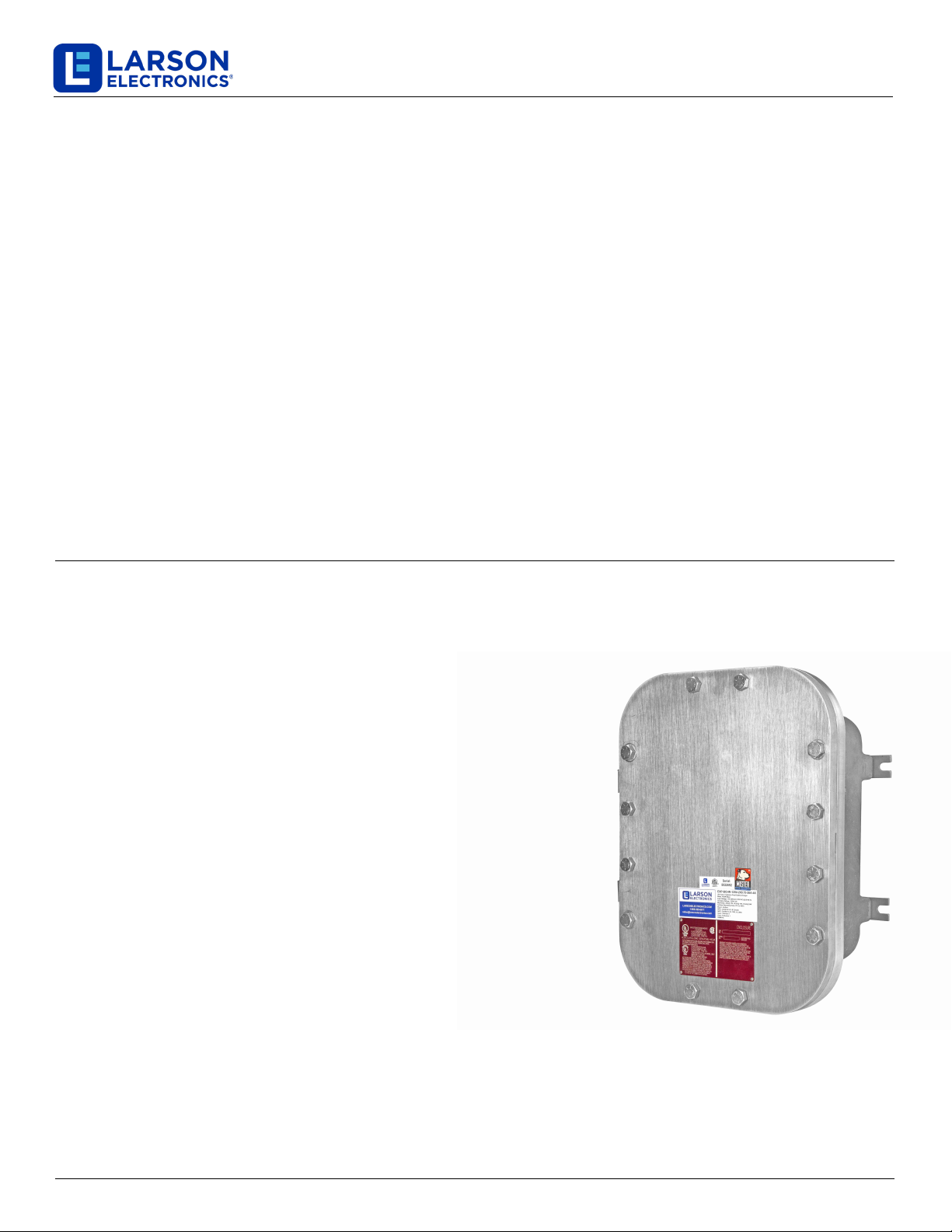
EXP-BCHR-120V-2X0.75-26A-4X
Larson Electronics, LLC Phone: (877) 348-9680 Fax: (903) 498-3364 www.larsonelectronics.com 2of 5
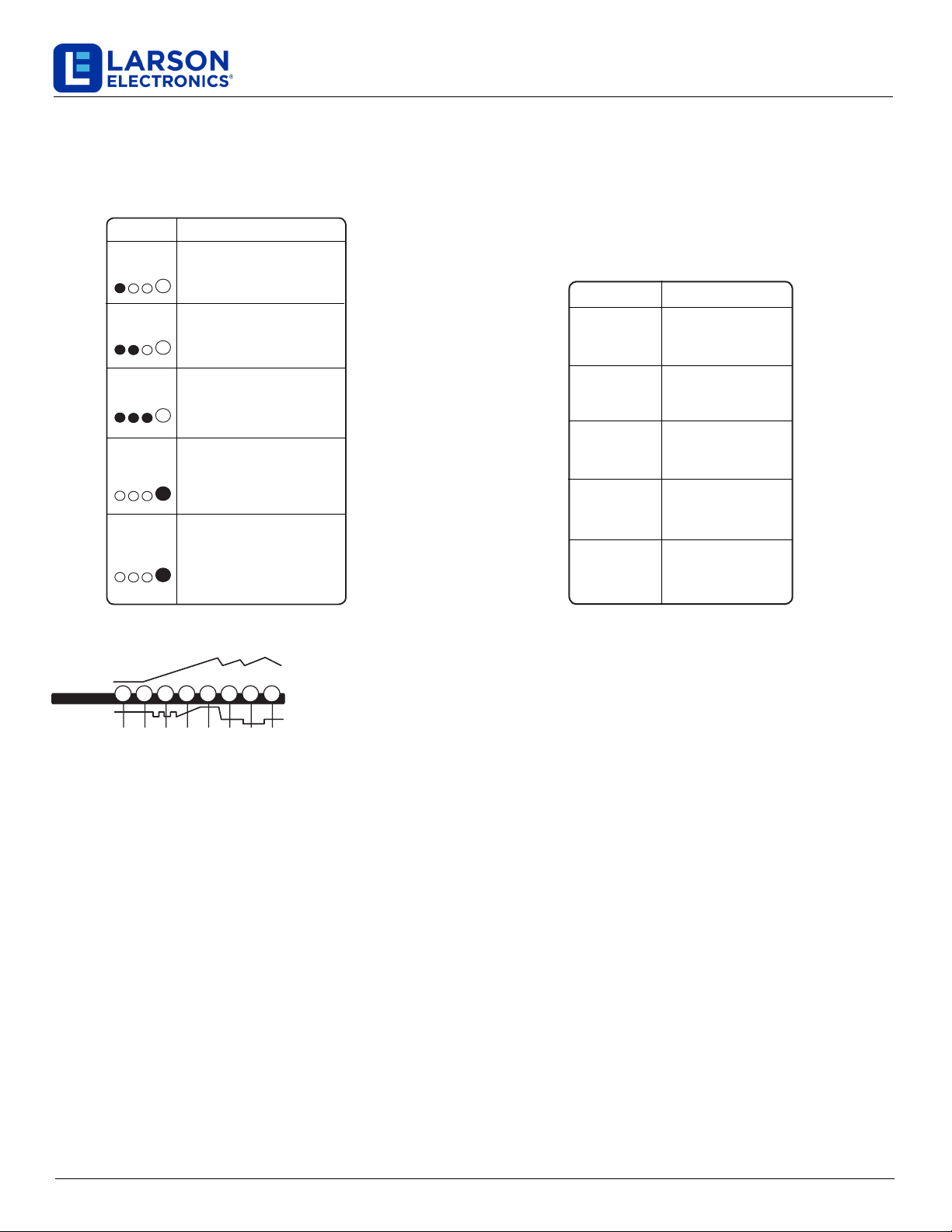
Mode Explanation
12V
NORM
Standby
12V
COLD/
AGM
14.8V | 26A | 50-500Ah Batteries
24V
NORM
29V | 13A | 25-250Ah Batteries
29.6V | 13A | 25-250Ah Batteries
No Power
14.5V | 26A | 50-500Ah Batteries
24V
COLD/
AGM
In Standby mode, the charger is not
charging or providing any power to
the battery. Energy Save is activated
during this mode, drawing microscopic
power from the electrical outlet. When
selected, an orange LED will illuminate.
For charging 12-volt Wet Cell, Gel Cell,
Enhanced Flooded, Maintenance-Free
and Calcium batteries. When selected,
a white LED will illuminate.
For charging 12-volt batteries in cold
temperatures below 50ºF (10ºC) or
AGM batteries. When selected, a blue
LED will illuminate.
For charging 24-volt Wet Cell, Gel Cell,
Enhanced Flooded, Maintenance-Free
and Calcium batteries. When selected,
a white LED will illuminate.
For charging 24-volt batteries in cold
temperatures below 50ºF (10ºC) or
AGM batteries. When selected, a blue
LED will illuminate.
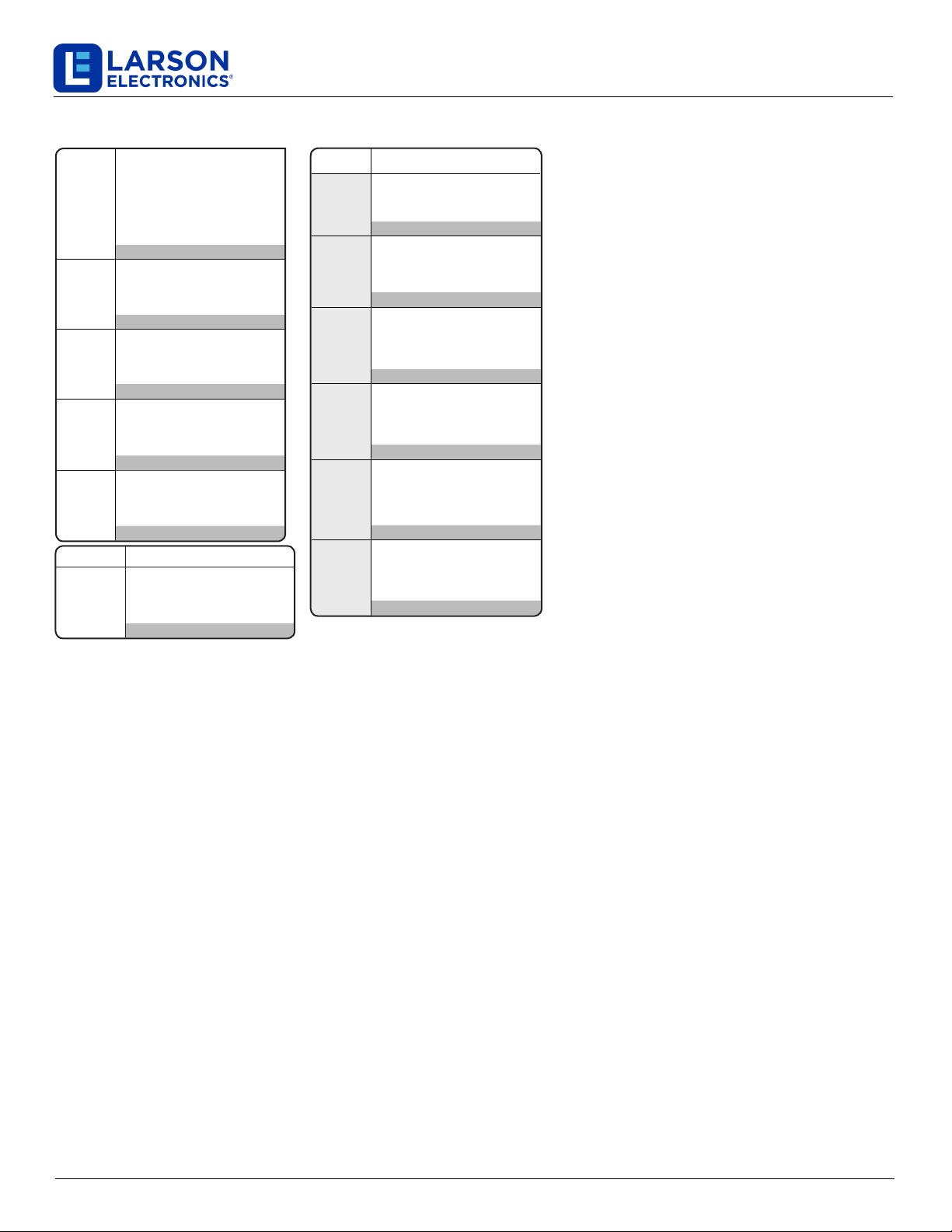
Mode Explanation
12V
AGM+
16V
AGM
12V
LITHIUM
15.5V | 26A | 50-500Ah Batteries
13.6V | 5A | Max 6A
19.45V | 20A | 25-250Ah Batteries
14.2V | 26A | 50-500Ah Batteries
16.5V | 1.5A | Any Capacity
19.6V | 20A | 25-250Ah Batteries
12V
REPAIR
16V
LITHIUM
For charging 12-volt advanced AGM
batteries, which requires a higher
than normal charging voltage. When
selected, a blue LED will illuminate.
For charging 16-volt AGM batteries,
which are commonly used in racing
vehicles. When selected, a blue LED
will illuminate.
For charging 12-volt lithium-ion
batteries, including lithium iron
phosphate. When selected, a blue
LED will illuminate.
An advanced battery recovery mode
for repairing and storing, old, idle,
damaged, stratied or sulfated
batteries. When selected, a red LED
will illuminate and ash
For charging 16-volt lithium-ion
batteries, including lithium iron
phosphate, which are commonly used
in racing vehicles. When selected, a
blue LED will illuminate.
13.6V
SUPPLY
Converts to a DC power supply for
powering any 12VDC device, like a tire
inator, oil changer, or as a memory
retainer when replacing a battery. When
selected, a red LED will illuminate.
Press & Hold
Press & Hold
Press & Hold
Press & Hold
Press & Hold
Press & Hold
Using 12V Lithium. [Press & Hold]
12V Lithium charge mode is designed for 12-volt
lithium-ion batteries only, including lithium iron
phosphate.
CAUTION: USE THIS MODE WITH CARE. THIS
MODE IS FOR 12-VOLT LITHIUM BATTERIES
ONLY. LITHIUM-ION BATTERIES ARE MADE AND
CONSTRUCTED IN DIFFERENT WAYS AND SOME
MAY OR MAY NOT CONTAIN A BATTERY
MANAGEMENT SYSTEM (BMS). CONSULT THE
LITHIUM BATTERY MANUFACTURER BEFORE
CHARGING AND ASK FOR RECOMMENDED
CHARGING RATES AND VOLTAGES. SOME
LITHIUM-ION BATTERIES MAY BE UNSTABLE AND
UNSUITABLE FOR CHARGING.
Using 12V AGM+. [Press & Hold]
12V AGM+ charge mode is designed for 12-volt
advanced AGM batteries only. Advanced AGM
batteries are a new battery technology typically found
in start-stop micro-hybrid vehicles. These batteries
accept a higher than normal charging voltage around
15.5-volts. 12V AGM+ charge mode is NOT suitable
for traditional AGM batteries. Consult the battery
manufacturer before using this mode.
CAUTION: USE THIS MODE WITH CARE. THIS
MODE IS FOR 12-VOLT LEAD-ACID ADVANCED
AGM BATTERIES ONLY. THIS MODE USES A HIGH
CHARGING VOLTAGE AND MAY CAUSE SOME
WATER LOSS IN WET (FLOODED) CELL
BATTERIES OR OVERCHARGE IN SOME
BATTERIES.
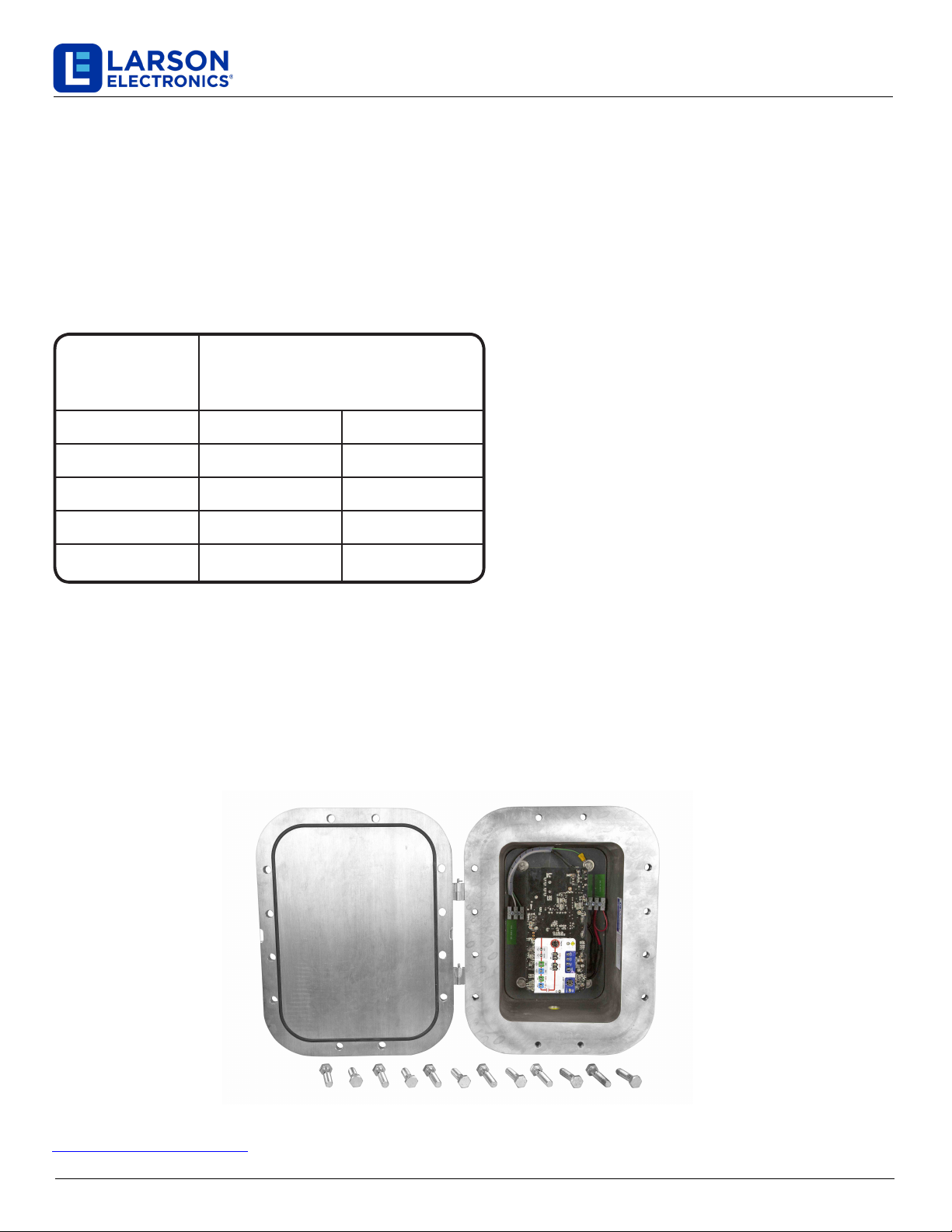
Mode Explanation
Delivers 30A for five (5) minutes to
jumpstart your dead vehicle battery.
When selected, a white LED will
illuminate. (Red Manual Mode)
5Min | 30A | 50-400Ah Batteries
Jump
CHARGE
Using 16V Lithium. [Press & Hold]
16V Lithium charge mode is for 16V lithium-ion batteries only, including lithium iron phosphate batteries. 16-volt lithium-ion batteries
are commonly found in racing vehicles, where the alternator might be removed, or used to improve the performance of the injector or
fuel pump.
CAUTION: THIS MODE IS FOR 16-VOLT LITHIUM BATTERIES ONLY. LITHIUM-ION BATTERIES ARE MADE AND
CONSTRUCTED IN DIFFERENT WAYS AND SOME MAY OR MAY NOT CONTAIN A BATTERY MANAGEMENT SYSTEM (BMS).
CONSULT THE LITHIUM BATTERY MANUFACTURER BEFORE CHARGING AND ASK FOR RECOMMENDED CHARGING RATES
AND VOLTAGES. SOME LITHIUM-ION BATTERIES MAY BE UNSTABLE AND UNSUITABLE FOR CHARGING.
Using 16V AGM. [Press & Hold]
16V AGM charge mode is for 16V AGM batteries only. 16-volt AGM batteries are commonly found in racing vehicles, where the
alternator might be removed, or used to improve the performance of the injector or fuel pump.
CAUTION: USE THIS MODE WITH CARE. THIS MODE IS FOR 16-VOLT AGM BATTERIES ONLY. DO NOT USE ON A 12-VOLT
BATTERY. CONSULT THE BATTERY MANUFACTURER BEFORE CHARGING AND ASK FOR RECOMMENDED CHARGING
RATES AND VOLTAGES.
Using 13.6V Supply. [Press & Hold]
13.6V Supply converts the charger to a constant current, constant voltage DC power supply. It can be used to power 12VDC devices,
including; tire inflators, oil changers, coffee pots, seat heaters and more. As a power supply, it can also be used to retain a vehicle’s
on-board computer settings during battery repair or replacement. 13.6V Supply provides 13.6-volts at 5A with overload protection at 6A
(Max).
CAUTION: THIS MODE IS FOR 12-VOLT LEAD-ACID BATTERIES ONLY. PRIOR TO USE, READ YOUR 12VDC DEVICE MANUAL
TO DETERMINE IF IT IS SUITABLE FOR USE WITH THIS MODE. BOTH THE SPARK PROOF AND REVERSE POLARITY SAFETY
FEATURES ARE DISABLED IN THIS MODE. DO NOT ALLOW THE POSITIVE AND NEGATIVE BATTERY CLAMP OR EYELET
TERMINAL CONNECTORS TO TOUCH OR CONNECT TO EACH OTHER AS THE CHARGER COULD GENERATE SPARKS.
CHECK THE POLARITY OF THE BATTERY TERMINALS BEFORE USING THIS MODE.
Battery Charging Modes