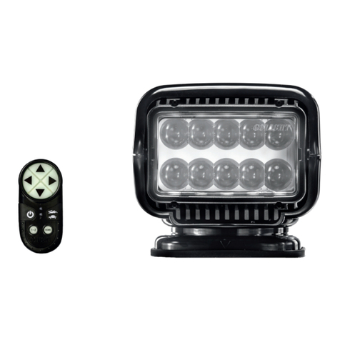
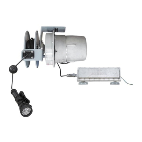
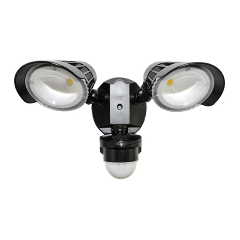
TheStryker Light isa2-SpeedSearchlightwithDirectional Flexibility
whichgives theoperatorafull 370°horizontalrotation anda 135°
verticaltiltwith fingertipcontrol. TheStryker Lightprovidessuperior
light
penetrationwiththenewCr5PentaBeamIItechnology.
Stryker Light HardWired - Permanent Mount:
Stryker Light Searchlight DashControl
Wiring Harness
Rockguard
PermanentMountingGasket
PermanentMountingPlate
MountingScrews
Stryker LightWireless- Permanent Mount:
Stryker LightSearchlight
RemoteControl(PerModelNumber)
2-23A12VBatteries
PermanentMountingGasket
PermanentMountingPlate
MountingScrews
Rockguard
Stryker Light Wireless- Magnetic Mount:
Stryker LightSearchlight
WirelessHandHeldRemote Control
2-23A12VBatteries
Rockguard
MOUNTING INSTRUCTIONS
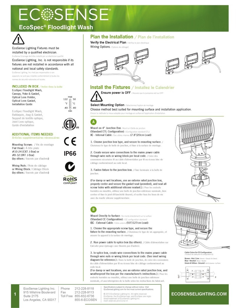
LightUnit/PermanentMount
Determinethelocationfor thelightonyourvehicleorboat. Remove
themountingplatefrom thelight. Center themountingplatewith the
visescrew onthe mountingplateto the back. Marktheholelocations
forthethree mountingscrews and drill apilot hole foreachwith1/8
inch bit. Fastenthestainless steel mountingplatewiththe 3 #10–
16x3/4typeAB crossrecessedpanhead
tappingscrews. Drill a1/4” hole(wireless) ora 5/8” hole(hard-wired)
inthe center ofthemountingplateopeningtoaccommodatethepower
wireorwiring harness and connector.Attachthe
connectorthatisaffixed tothe undersideof the lighttothe
correspondingconnectoronthewiringharness(hard-wired).
Positiontheconnectionpoint beneaththe mountingsurface,and apply
siliconesealantaroundwiretoseal thedrilledopening.
Wetthemountingsurfacewitha smallamountof water or
lubricantforeasierinstallation,then placethe lightoverthe
mountingplate by slidingthefront of thelight over thefront ofthe
mountingplate, first pullthelight backwards,thenseatthe back ofthe
light ontothemountingplate. Displacethe back ofthegasket and
installthevise screw(provided).Tightenthe visescrewusingaPhillips
headscrewdriver. Replacethegasket.
Power Supply
Connect the deutsch connectors for all cables. There is one that
connects to the golight and one that connects to the transformer.
Be sure these are securely fastened. Then plug the transformer
into a compatible outlet providing 110V AC. The light is now
powered and will operate with the remote control.
DashControl/PermanentMount
Determinetheappropriatelocationforthedashmountcontroland
createa2inchopeningtoaccommodate the cylinderontherearof
theremote. Removethe outer rubbercoverandaffix thecontrolto
thedashwiththefourscrewsprovided. Theword”TOP”is em-
bossedonthecontrol andshouldbesituatedaccordingly. Allwiring
shouldbeundertakenwithpowerremovedfrom thesystem. First,at-
tachtheconnectorthat is affixed tothecontrol tothecorresponding
connectoronthewiringharness. Next, join the leadsat theremote
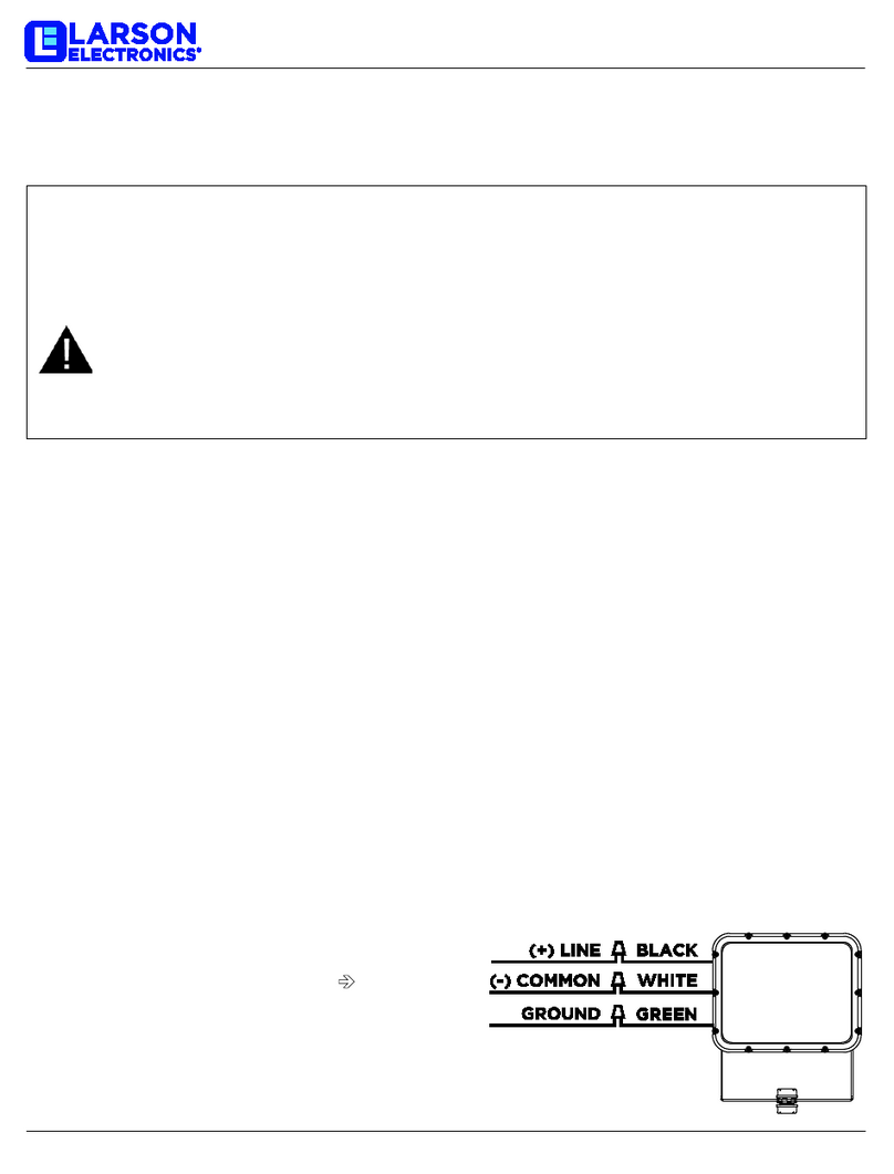
to12voltDC powerwithappropriateautomotivewireattachments;
theredwireisthe positiveleadandtheblackwire is thenegative
lead--theunitispolaritysensitive andcaremust betakentoobserve
this. Note: Once power isappliedtothesystemthelight will pan
andtilt priortobulbillumination. Asa safety feature,the control is
backlittoindicatebulbilluminationonly.
Each spotlight needstobewiredonasinglededicatedcircuit and
thepowerfused at 10 amps. With the powerconnected,your light is
readyforoperation.
WirelessDashControl
Ifyouhavea wireless dash control,please notethat it isvitalfor this
tobe attachedto a flat / smooth surfacewith the 4 mountingscrews
included. Thearrowunderthe rubbercovershouldpoint up.
BATTERY INSTALLATION AND REMOVAL FOR TRANSMITTER
Removebatterycover:forwirelesshand-heldtransmitter,remove
phillipsheadscrewtoremove cover.Forwireless dashmountremote,
simplyremovetheexteriorrubbercover. Withbatterycompartment
nowexposed,insert batteriesaccordingtothecorrect polarityor
gentlyremove batteriesbygrabbingthepositive endandlifting up.
PROGRAMMABLE REMOTE INSTRUCTIONS
The Stryker Lightiscontrolledwithaprogrammable
remote
with2187different channels. This featureallowsyou
thefreedomtochangethechannelselection,andthereceiver re-
learnsthenewselection. Thislight hasbeenpre-programmedatthe
factory,anditisnot necessarytore-programthetransmitter,unless
youexperienceoutsideinterference.Toprogramtransmitter:
1. IMPORTANT D:isconnect power.
2.
Removebatterycoverfromremotecontrol.
3.
Set the 7 dipswitches to a selection of your choice. There are 3
positions on each; positive,negativeandneutral. Use asmall
screwdriverandselectapositionforeachdipswitch. *Please
note thattheorientationof the +/-switchpositionsmay vary
amongdifferent modelsofwirelessremotecontrols.
4.
InsertbothGP23A 12V batteries. Besurebatteries have
adequatecharge.
5.
Replacebatterycover.
a.
Depress the on/off button and hold itdown. RedLED will
light.
b.
Whileholdingtheon/off buttondown,reinstallthepower
(replacefuseorconnectvehiclebattery).
c.
Keepon/off buttondepressedfor5-6seconds, and
thenrelease. Thelightshouldnowbeprogrammed.
OPERATIONOFSTRYKER LIGHT
1.
Usingtheremotecontrol,turnonthelight by depressingthe on/
offbutton.
2.
Withthejoystick onthe dashcontrol,rotateyourlighttothe
desiredlocation.
3.
Thespeedofthelight rotation canbecontrolledby depress-
ingthefast/slow buttononetimeandbydepressingit againto
restoretheoriginalspeed.
4.
Thespotlightshouldnot beturnedonwhenthesnapon lens
cover(rockguard)isattached.Thehardwireddash control willbe
backlit whenthebulb is illuminated.
USAGE:
»This light isintendedfor off-roadand utilityuse only
»This lightis intendedtobe mounted outsidethevehiclewhilein
use
»This lightmay only bedisassembledandrepairedbyan
authorized representative
MISUSE:
»This lightis not approvedforroad or highway use
»This light isnot approvedfor underwateruse
»Thislightisnotapprovedfor invertedmounting
»This lightisnot approvedforuse insideavehicleorenclosureand
powershouldbedisconnectedpriorto placingthelight insuch
circumstance
»This light may bedamagedif operatedinicing conditions
»Thislight mayonlybedismantledbyanauthorizedGolightrepre-
sentative
»
Any violation of the above referenced misuses will be
considered groundsforwarrantyrefusal
