manuals.online logo
Brands
  1. Home
  2. •
  3. Brands
  4. •
  5. Larson Electronics
  6. •
  7. Industrial Equipment
  8. •
  9. Larson Electronics EXP-GFCI-20A User manual

Larson Electronics EXP-GFCI-20A User manual

EXP-GFCI-20A
Larson Electronics, LLC Phone: (800) 369-6671 Fax: (903) 498-3364 www.larsonelectronics.com 1of 3
Explosion Proof 20-Amp Ground Fault Circuit Interrupter
20-Amp GFCI - Malleable Iron Body
Instruction Manual
Thank you for your purchase of the Larson Electronics EXP-GFCI-20A.
WARNING:
READ CAREFULLY BEFORE INSTALLING FIXTURE. RETAIN THESE INSTRUCTIONS FOR FUTURE REFERENCE.
CRITICAL SAFETY INSTRUCTIONS:
•INSTALLATION SHOULD ONLY BE CONDUCTED BY A QUALIFIED ELECTRICIAN IN ACCORDANCE WITH NEC AND ANY
RELEVANT LOCAL BUILDING CODES.
•RISK OF FIRE OR ELECTRIC SHOCK. FIXTURE INSTALLATION REQUIRES KNOWLEDGE OF LUMINAIRES ELECTRICAL
SYSTEMS. IF NOT QUALIFIED, CONTACT A QUALIFIED ELECTRICIAN.
•BE CERTAIN ELECTRICAL POWER IS OFF BEFORE AND DURING INSTALLATION AND MAINTENANCE.
•MAKE SURE THE SUPPLY VOLTAGE IS THE SAME AS THE RATED LUMINAIRE FIXTURES VOLTAGE.
•TO PREVENT WIRING DAMAGE OR ABRASION, DO NOT EXPOSE WIRING TO EDGES OF SHEET METAL OR SHARP
OBJECTS. SUITABLE FOR DAMP LOCATIONS.
WARNING
TO AVOIDTHE RISKOF FIRE,EXPLOSION OR ELECTRIC SHOCK, THIS PRODUCT SHOULD BE INSTALLED,
INSPECTEDAND MAINTAINEDBY A QUALIFIED ELECTRICIANONLY, IN ACCORDANCEWITHALL
APPLICABLEELECTRICAL CODES.
TO AVOIDELECTRIC SHOCK:
•BE CERTAIN ELECTRICAL POWER IS OFF BEFORE AND DURING INSTALLATION AND MAINTENANCE.
•PRODUCT MUST BE CONNECTED TO A WIRING SYSTEM WITH AN EQUIPMENT-GROUNDING
CONDUCTOR.
TO AVOID EXPLOSION:
•MAKE SURE THE SUPPLY VOLTAGE IS WITHIN THE VOLTAGE RATING.
•ENSURE THE MARKED T RATING IS LESS THAN THE IGNITION TEMPERATURE OF THE HAZARDOUS
ATMOSPHERE.
•DO NOT OPERATE IN AMBIENT TEMPERATURES ABOVE THOSE INDICATED ON THE PRODUCT
NAMEPLATE.
•DO NOT OPERATE IF THE LENS, CORD, SEALS, HOUSING, RECEPTACLES, ETC. IS CRACKED OR
DAMAGED. IF SO, DISCONTINUE USE AND CONTACT MANUFACTURER FOR REPLACEMENT PARTS.
•ALL FASTENERS SHOULD BE PROPERLY SEATED.
The EXP-GFCI-20A from Larson Electronics is an explosion proof 20-amp ground fault circuit interrupter (GFCI) that provides
protection for electrically operated devices. This explosion proof GFCI is rated for Class I Divisions 1 & 2 Groups B, C and D, Class II
Divisions 1 & 2 Groups E, F and G and Class III hazardous areas. The EXP-GFCI-20A is ideal for use in environments with corrosive
atmospheres, wet locations and in areas that contain potentially explosive gases, dusts or other hazardous materials.
EXP-GFCI-20A
Larson Electronics, LLC Phone: (800) 369-6671 Fax: (903) 498-3364 www.larsonelectronics.com 2of 3
NOTE: All installations must comply with applicable
local and/or national electrical codes, as well as safety
practices for this type of equipment.
This receptacle enclosure is for use with 2-pole, 3-wire,
120 volt AC 60Hz, 15 (or 20) Amp, 1 Horsepower
maximum circuits. The enclosure is designed for
environments as defined in Article 500 of the National
Electrical Code.
For use with EPP-15A and EPP-20A type explosion
proof plugs.
DIRECTIONS FOR INSTALLATION
GFCI Box
1.) Wire the system referring to the appropriate wiring
diagram inside box. Special care should be taken to
distinguish between the line and load side
connections.
2.) Replace the cover and tighten screws to 5 ft-lbs.
3.) Enclosure must be vertical before plugging into
existing power source. Hook around conduit or
scaffolding; or similar.
4.) Make sure that the circuit breaker indicates "OFF"
before inserting plug into power source. Follow
manufacturers operation instructions to engage plug
into the power receptacle.
5.) With circuit breaker "OFF", plug the device
(requiring ground fault protection) into the
receptacle.
6.) After both the supply circuit and the load circuit have
been connected, the circuit breaker can be turned to
the "ON" position. The pilot light will light indicating
power to the receptacle.
OPERATIONAL DATA
The devices used in this enclosure are electrical arcing
devices. The enclosure in which they are installed
includes internal seals which isolate these devices from
the supply circuit. Depending on your application,
additional external seals may be required by NEC
articles, 501-5 & 502-5. In addition, the enclosure must
be marked with a cautionary statement such as:
"CAUTION: Disconnect this device from the supplying
circuit before entering. Keep assembly tight while
circuits are alive."
This statement must be permanently visible after the
enclosure has been installed.
NOTE: Never hang this enclosure by the cord! The cord
and plug assembly (cord set) must be inspected for
wear before each use. For replacement, contact
manufacturer.
If the pilot light does not light with circuit breaker in the
"ON" position, check the following conditions:
a) Circuit breaker tripped - Make sure that the circuit
breaker has not tripped (turn handle toward
"RESET"). Clear the load circuit of all faults before
turning "ON".
b) Lamp failure - Disconnect plug from power supply
and replace the lamp (unscrew lens guard
assembly).
c) Circuit breaker/ground fault malfunction -
Replace the circuit breaker.
RECEPTACLE OPERATION
Electrical connection between receptacle and plug is
accomplished after plug fully inserts into receptacle and
rotated clockwise.
1.) Lift receptacle door and locate polarization on mating
plug pin and receptacle face. Insert plug straight all
the way into receptacle until it cannot go further.
2.) Rotate plug clockwise limit (37º), this closes internal
contacts and completes circuit. This also
mechanically locks plug into receptacle so it cannot
be pulled out.
3.) To remove plug, push plug inward and turn to
counterclockwise, pull plug straight out.
MAINTENANCE DATA
This device should be checked for proper ground fault
operation on a monthly basis. While connected to the
power supply, turn circuit breaker handle "ON" and
depress the push-to-test button. The circuit breaker
should trip and the pilot light should turn off. Turn handle
to reset the circuit breaker.
WARNING: Disconnect this device from supplying
circuit before entering. CAUTION: The surfaces
between the covers and the box is a flame path and
must be kept clean.
Tighten receptacle and cover screws as follows:
1/4" screws: 5 ft-lbs, 3/8" screws: 23 ft-lbs.
Inspect components for wear before each use. If
damaged, the parts must be replaced at once. Refer to
the Parts Drawing below for specific replacement part
numbers.
EXP-GFCI-20A
Larson Electronics, LLC Phone: (800) 369-6671 Fax: (903) 498-3364 www.larsonelectronics.com 3of 3
GROUND-FAULT CIRCUIT INTERRUPTER (GFCI)
In the event of a ground fault, a GFCI will trip and quickly stop the flow of electricity to prevent serious injury.
Definition of a ground fault:
Instead of following its normal safe path, electricity passes through a person's body to reach the ground. For example, a
defective appliance can cause a ground fault.
A GFCI receptacle does NOT protect against circuit overloads, short circuits, or shocks. For example, you can still be
shocked if you touch bare wires while standing on a non-conducting surface, such as a wood floor.
NOTE:
GFCI's contain a lockout feature that will prevent RESET if:
• There is no power being supplied to the GFCI.
• The GFCI is miswired due to reversal of the LINE and LOAD leads.
• The GFCI cannot pass its internal test, indicating that it may not be able to provide protection in the event of a ground
fault.
GFCI TEST
Use an approved GFCI tester or plug an electrical device, such as a lamp into the receptacle on which you are working.
Turn the lamp or device ON. Then, press the TEST button on the GFCI box and power should immediately be switched
off. If not, contact an electrician. Press the RESET button to restore power.
MAINTENANCE
There are no serviceable parts inside the fixture. However, it is good practice to routinely clean and check the
fixture for proper function.
•Disconnect power running to the unit and be sure the fixture iscool to the touch.
•Use a non-abrasive cleaning solution to clean the unit.
USE AND CARE
Unauthorized modification may impair the function and/or safety of this device and could affect the life of the equipment.
Always check for damaged or worn out parts before using the device. Store it in a secure place out of the reach of
children when not in use.Inspect for good working condition prior to storage and before re-use.
REPLACEMENT PARTS
The EXP-GFCI-20A is designed to provide years of reliable performance. Should the need for replacement parts arise,
please contact Larson Electronics.
THESE INSTRUCTIONS MAY NOT COVER ALL DETAILS OR VARIATIONS OF THIS PRODUCT FOR YOUR EQUIPMENT OR INSTALLATION REQUIREMENTS.
SHOULD FURTHER INFORMATION NOT COVERED BY THESE INSTRUCTIONS BE REQUIRED, PLEASE CONTACT LARSON ELECTRONICS BY EMAIL AT
SALES@LARSONELECTRONICS.COM OR BY PHONE AT 1-800-369-6671 FOR FURTHER ASSISTANCE.
PLEASE VISIT LARSONELECTRONICS.COM FOR WARRANTY AND RETURN INFORMATION.

Other Larson Electronics Industrial Equipment manuals

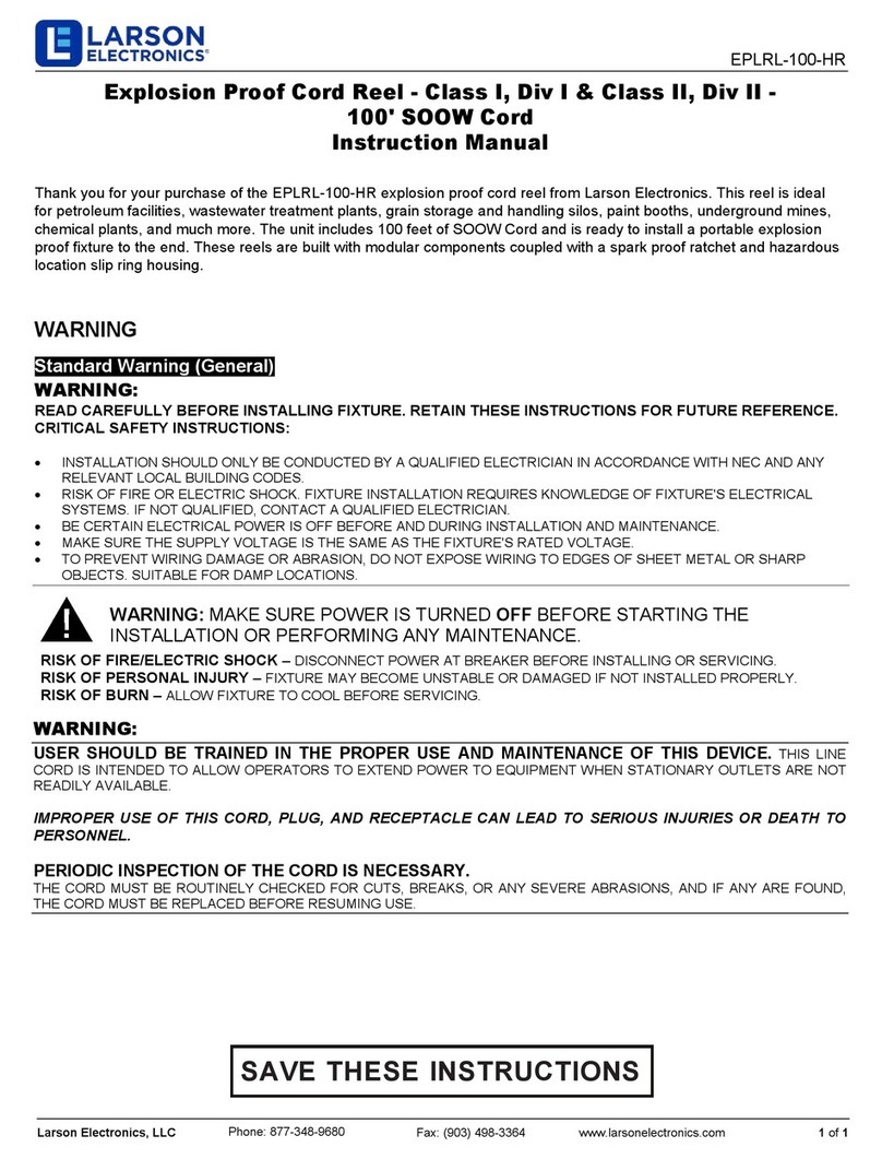
Larson Electronics EPLRL-100-HR User manual

Larson Electronics

Larson Electronics EPLRL-100-HR User manual

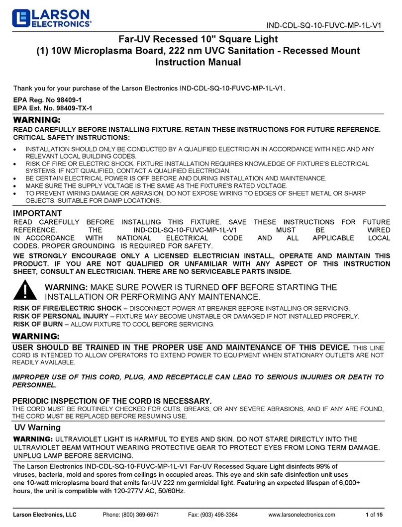
Larson Electronics IND-CDL-SQ-10-FUVC-MP-1L-V1 User manual

Larson Electronics

Larson Electronics IND-CDL-SQ-10-FUVC-MP-1L-V1 User manual

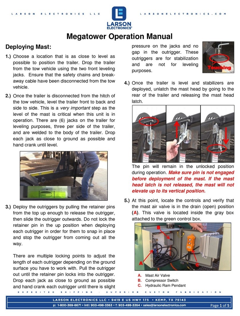
Larson Electronics Megatower RNT-WCDE-11-PLM50-6X500LTL-LED User manual

Larson Electronics

Larson Electronics Megatower RNT-WCDE-11-PLM50-6X500LTL-LED User manual

Larson Electronics HLX-SWG-EB Series User manual

Larson Electronics

Larson Electronics HLX-SWG-EB Series User manual

Larson Electronics Pneumatic Megatower User manual

Larson Electronics

Larson Electronics Pneumatic Megatower User manual

Popular Industrial Equipment manuals by other brands

igus robolink quick start guide

igus

igus robolink quick start guide

MB 700 Series Operation manual

MB

MB 700 Series Operation manual

Siemens SINUMERIK Equipment manual

Siemens

Siemens SINUMERIK Equipment manual

ABB ACx580-01-02A6-4 Service instructions

ABB

ABB ACx580-01-02A6-4 Service instructions

Metso HP Series Assembly and Disassembly

Metso

Metso HP Series Assembly and Disassembly

VALLEY CRAFT F89700 instruction manual

VALLEY CRAFT

VALLEY CRAFT F89700 instruction manual

JETStream J-FORCE JF6X15 Product instructions

JETStream

JETStream J-FORCE JF6X15 Product instructions

FLEXPOWER TWO VFXR Series Setup and Programming

FLEXPOWER

FLEXPOWER TWO VFXR Series Setup and Programming

Conquip Smoking Shelter SS901AA-07200 user guide

Conquip

Conquip Smoking Shelter SS901AA-07200 user guide

Parker RC Series Maintenance instructions

Parker

Parker RC Series Maintenance instructions

Reich Kupplungen Arcusaflex WN Series Mounting and Maintenance Instructions

Reich Kupplungen

Reich Kupplungen Arcusaflex WN Series Mounting and Maintenance Instructions

SCHUNK PGH 150 operating manual

SCHUNK

SCHUNK PGH 150 operating manual

OMCA SMF Use and maintenance manual

OMCA

OMCA SMF Use and maintenance manual

ABB HT609106 Operation manual

ABB

ABB HT609106 Operation manual

Huawei FusionDC1000A quick guide

Huawei

Huawei FusionDC1000A quick guide

REMS Cobra 22 manual

REMS

REMS Cobra 22 manual

Surefire QuickDraw Lite Operator's manual

Surefire

Surefire QuickDraw Lite Operator's manual

Aventics TRR Series Repair instruction

Aventics

Aventics TRR Series Repair instruction

manuals.online logo
manuals.online logoBrands
  • About & Mission
  • Contact us
  • Privacy Policy
  • Terms and Conditions

Copyright 2025 Manuals.Online. All Rights Reserved.