Larson Electronics Megatower RNT-WCDE-11-PLM50-6X500LTL-LED User manual

Megatower Operation Manual
Page 1of 5
Deploying Mast:
1.) Choose a location that is as close to level as
possible to position the trailer. Drop the trailer
from the tow vehicle using the two front leveling
jacks. Ensure that the safety chains and break-
away cable have been disconnected from the tow
vehicle.
2.) Once the trailer is disconnected from the hitch of
the tow vehicle, level the trailer front to back and
side to side. This is a very important step as the
level of the mast is critical when this unit is in
operation. There are (6) jacks on the trailer for
leveling purposes, three per side of the trailer,
and are welded to the body of the trailer. Drop
each jack as close to ground as possible and
hand crank until level.
3.) Deploy the outriggers by pulling the retainer pins
from the top up enough to release the outrigger,
then slide the outrigger outwards. Do not lock the
retainer pin in the up position when deploying
each outrigger in order for them to snap in place
and stop the outrigger from coming out all the
way.
There are multiple locking points to adjust the
length of each outrigger depending on the ground
surface you have to work with. Pull the outrigger
out until the retainer pin locks into the outrigger.
Drop each jack as close to ground as possible
and hand crank each outrigger until there is slight
pressure on the jacks and no
gap in the outrigger. These
outriggers are for stabilization
and are not for leveling
purposes.
4.) Once the trailer is level and stabilizers are
deployed, unlatch the mast head by going to the
rear of the trailer and releasing the mast head
latch.
The pin will remain in the unlocked position
during operation. Make sure pin is not engaged
before deployment of the mast. If the mast
head latch is not released, the mast will not
elevate up to its vertical position.
5.) At this point, locate the controls and verify that
the mast air valve is in the drain (open) position
(A). This valve is located inside the gray box
attached to the green control box.
A
B
C
A. Mast Air Valve
B. Compressor Switch
C. Hydraulic Ram Pendant
Touching

Megatower Operation Manual
Page 2of 5
6.) Once your trailer is level and the outriggers are
fully deployed, it is time to power on the
unit. Locate the keys to the generator.
Open the control panel of the genset. Insert key
and turn to the ON position (1). Wait for the
control module to boot (2). Make sure the main
breaker is OFF (3). Press the green Start button
and wait for the generator to start. Once the
generator has started, turn the main breaker
ON.Note: Check to ensure the fuel tank
has an adequate amount of fuel before
running the generator.
Check the top of the control box and you should see
a red beacon light flashing. If you do not see this
light flashing, make sure the mast retention pin is
pulled back all the way and NOT engaged. The
mast retaining pin is located on the right side of the
green job box. You will notice a black pistol grip level
handle (D). Once located, ensure the retaining pin is
pulled all the way back towards the operator. Once
this is confirmed, the beacon on top of the green job
box should be blinking red. The mast will not elevate
horizontally if this pin is engaged.
Once you have verified that the…
Trailer dropped from the tow vehicle
Leveling jack are deployed and
Trailer is level
Outriggers are deployed
Mast head is unlatched
Generator is running
Mast retainer pin is in the open
position
Mast air valve is in the drain position
Red LED beacon is blinking
…the mast is ready for deployment.
7.) Inside the control box on the side of the green job
box is an air valve, compressor switch, and
orange pendant. The orange pendant operates
the hydraulics that control horizontal movement
of the light mast. There is an up and a down
button. Up raises the mast to the upright position
for deployment while down lowers the mast for
1
2
3
D
WARNING: Never operate this unit above 40psi!

Megatower Operation Manual
Page 3of 5
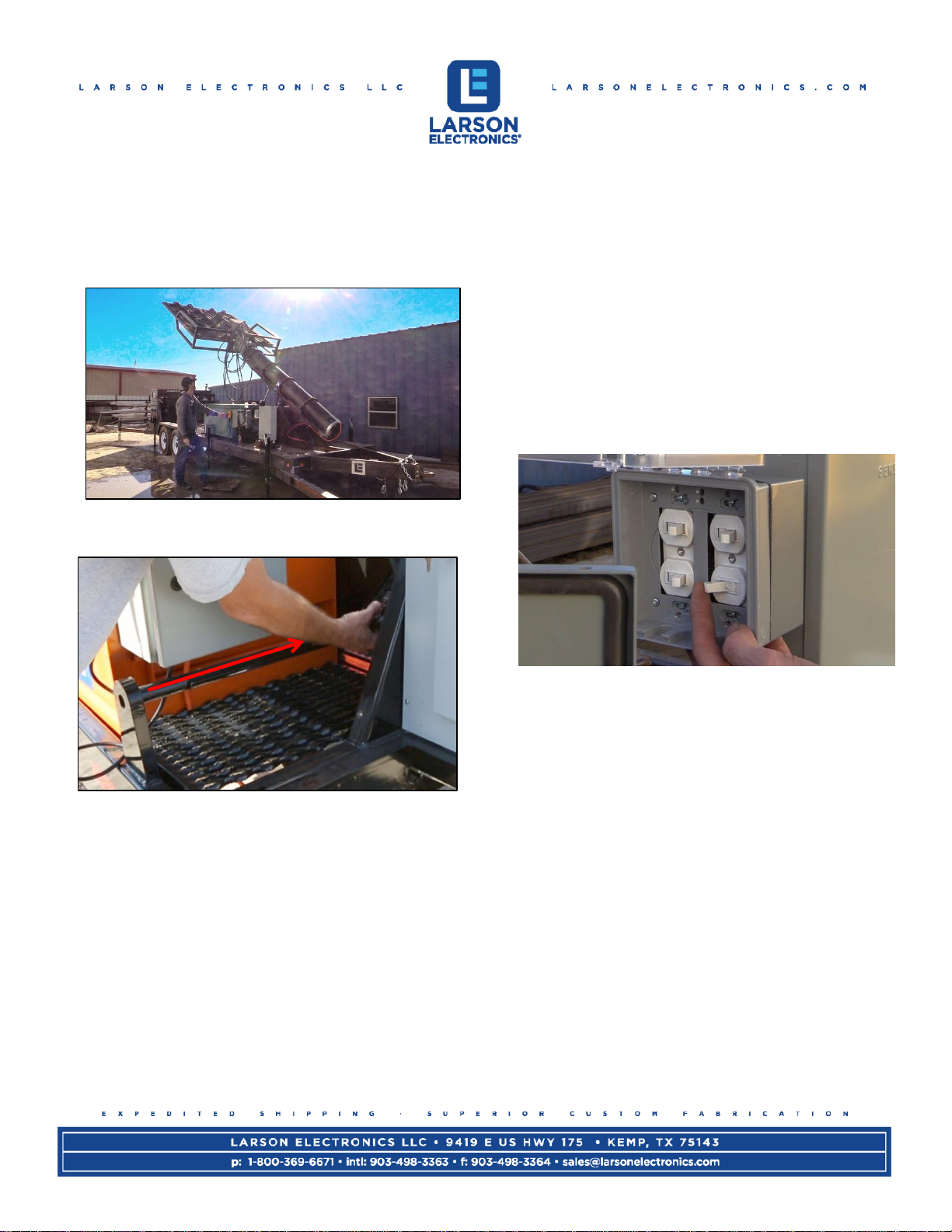
transport/storage. At this point, the mast is ready
to be elevated. Press the up button on the
orange pendant and the mast will start to elevate
horizontally to its upright position.
Elevate the mast to its full 90 degrees and verify
that the mast is still level.
8.) Once mast is elevated, install the mast retaining
pin. Push the mast retaining pin opposite of the
operator, and then rotate the pin down until it
locks into place. The red beacon light will turn off
once the pin is locked in place. At this point, the
hydraulics will no longer function while the mast
is elevated.
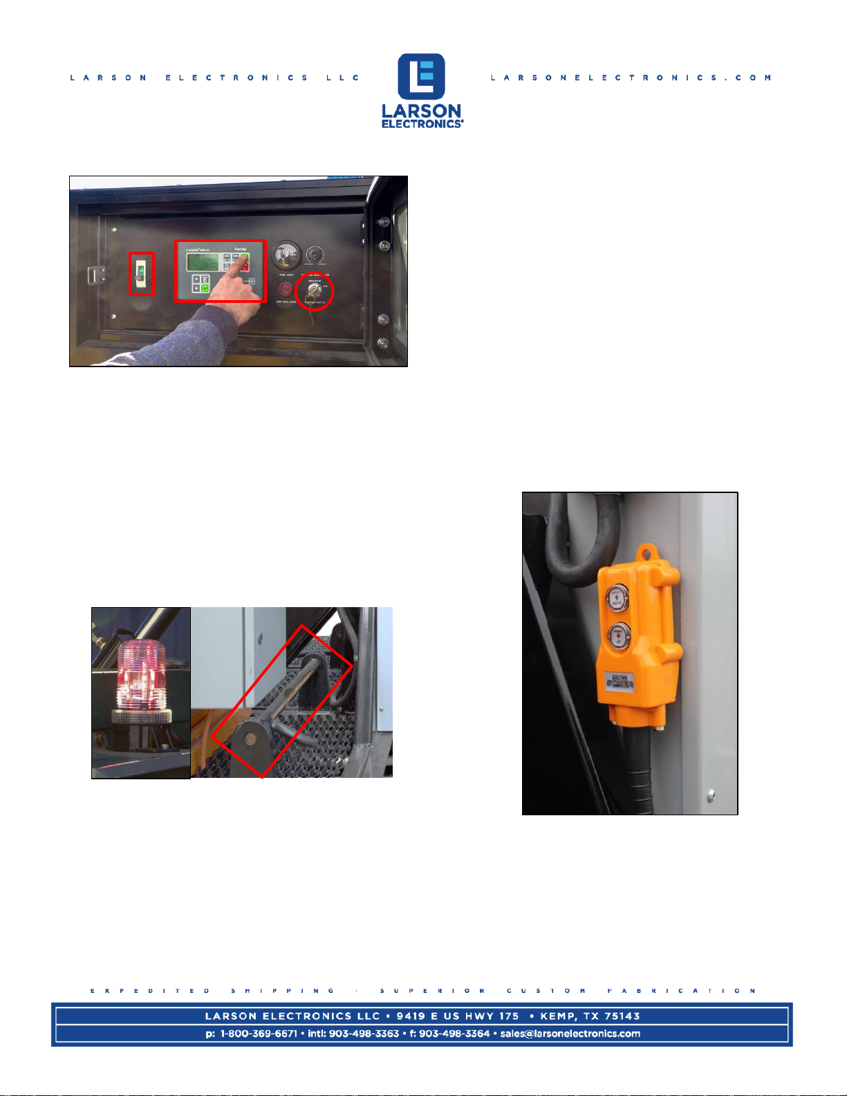
9.) Inside the control panel, rotate air valve to deploy
(closed) position. Locate the compressor switch
and turn switch ON. You should hear the air
compressor engage. Once enough air pressure
is built, the mast will start to vertically elevate.
The mast can take up to 20 minutes to fully
deploy and it is normal for several compressor
cycles during this time. WATCH CABLES TO
ENSURE THEY DO NOT GET SNAGGED
WHILE ELEVATING! Cables are positioned
designed to prevent snags but keep a look out
when elevating. Once fully deployed, the
compressor should only cycle every 20 minutes
for 15 seconds. The compressor switch should
remain in the ON position for the duration
deployed in order to keep the mast elevated.
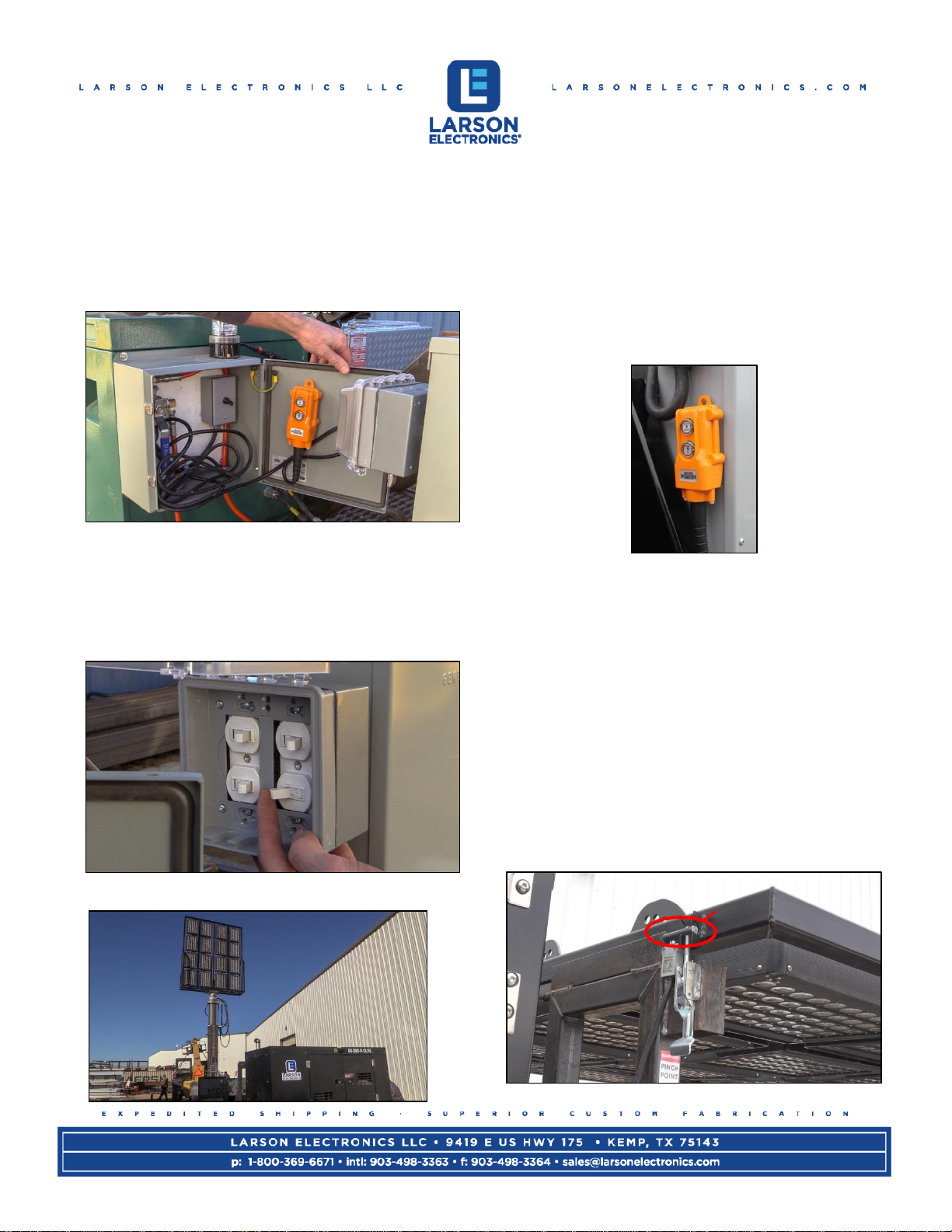
10.) Once the mast is fully deployed, it is time to
power on the lights. This is done by flipping the
four switches located on the breaker box
opposite the control box. The lights are wired in
banks of four, from left to right. Each switch
operates a single bank: left, center left, center
right, right. With this setup, operators can choose
the amount of illumination required for the
specific task at hand.
At this point the mast is fully deployed and
ready for use.
WARNING:The light mast at 50’ is rated for wind
speeds up to 25 MPH. If deployed in wind speeds
higher than this, the mast must be guyed or the mast
will need to be lowered to 25’. At 25’ the mast is rated
for 40 MPH. Any higher wind speeds, and we suggest
that you lower the mast completely. Failure to do so
may result in damage to the mast.

Megatower Operation Manual
Page 4of 5
Lowering the mast:
1.) When preparing to lower the mast, open the
control box and turn the compressor off.
Once off, turn the air valve located in the gray
box to drain. It may take the mast 10 to 15
minutes to fully lower. This is normal. You will
audibly hear the air releasing from the mast.
Note: Leave the valve in the drain position so it
will be ready for next use.
2.) Turn the lights off.
3.) The mast should be in the lower position and
ready to lay horizontally for transport. Remove
the mast retaining pin located on the right side of
the green job box. There is a black pistol grip
handle on the retaining pin. Rotate this pin
upwards and slide it back towards the operator
until the pin is clear of the mast.
4.) Once retaining pin is clear, locate the orange
pendant inside the gray box with the air valve.
Depress the down button on the pendant until the
mast is fully lowered horizontally.
5.) Access generator controls and switch main
breaker OFF. Press the red OFF button and turn
the key OFF. Close access door.
6.) Lock the mast head into place by going to the
back of the trailer and latching the pin. Locking
the head prevents unnecessary movement
during transport.
Locked

Megatower Operation Manual
Page 5of 5
7.) At this point, the outriggers can be retracted.
Ensure each outrigger locks into place and the
jacks have proper ground clearance.
8.) The trailer is now ready for hookup to a tow
vehicle. Once tied to a tow vehicle, raise all
leveling jacks. Ensure that safety chains, brake-
away device, and trailer lights are connected.
Test trailer lights to ensure stop/tail/brake lights
work before operating vehicle on public
roadways.
If you have any questions about your new
device please call the Manufacture.

Megatower Operation Manual
MAST TROUBLESHOOTING
No power to unit.
oCheck to ensure the generator is running.
oCheck main breaker switch at generator is turned ON.
oCheck breaker panel and ensure nothing has been tripped or is off.
Lift ram pendant control is not responsive and mast will not rise to its vertical position.
oCheck mast head has been unlatched and the locking pin has been released.
oCheck mast retention pin is disengaged and pulled out all the way.
oCheck mast head hasn’t extended during transport. If the mast head is not fully retracted
pressing up against the mast retract sensor, this will disable the hydraulic ram.
The air compressor will not engage and the mast does not elevate.
oCheck mast is fully upright to its vertical position and engaging the mast upright sensor
towards the base of the mast.
oCheck mast retention pin is fully engaged and locked in place.
oCheck all breakers for generator and breaker panel.
oCheck and press the air compressor overload protection switch (2) in diagram below.
The mast will not lower to its horizontal position. The lift ram is unresponsive.
oCheck the mast is fully lowered and engaging the mast retract sensor.
oCheck mast retention pin is fully disengaged.
oCheck that the mast head locking pin has not been engaged.
oCheck to ensure the generator is running and all breakers are turned ON.
MAST RETENTION PIN
MAST HEAD LOCKING PIN
MAST UPRIGHT
SENSOR
MAST RETRACT
SENSOR
COMPRESSOR OVERLOAD
PROTECTION SWITCH RESET
This manual suits for next models
1
Table of contents
Other Larson Electronics Industrial Equipment manuals

Larson Electronics
Larson Electronics IND-CDL-SQ-10-FUVC-MP-1L-V1 User manual

Larson Electronics
Larson Electronics Pneumatic Megatower User manual

Larson Electronics
Larson Electronics EPLRL-100-HR User manual

Larson Electronics
Larson Electronics EXP-GFCI-20A User manual

Larson Electronics
Larson Electronics HLX-SWG-EB Series User manual