Larson Electronics RCL-336 User manual

RCL-336
Larson Electronics, LLC Phone: (800) 369-6671 Fax: (903) 498-3364 www.larsonelectronics.com
1of 10
Remote Control Thermal Imaging Camera System - 12V - Wireless
or Wired Remote - 6" LCD Monitor
Instruction Manual
Please read these instructions before using your new remote control thermal imaging camera system.
The camera's wireless remote are designed to be attached to a vehicle using a magnetic or per-manent mount and
operated by a wireless remote control. Each spotlight has 360° horizontal rotation and 135° vertical tilt.
Introduction
The Thermal Imaging Camera System can help a driver identify pedestrians in front of their vehicle during low light
situations. The Thermal Imaging Camera System is capable of identifying the objects generating heat, displaying them
on a screen, and improving the driver’s experience.
The infrared thermal imager detects infrared energy (heat) through a non-contacting method, converts it to an electric
signal, and generates a thermal image that appears on a screen. The infrared thermal imager is an inspection device
which can be used to calculate the temperature. It can also precisely quantize and measure the detected heat, so that
you can observe the thermal image and accurately identify animals and pedestrians.
Per the statistics of the National Highway Traffic Safety Administration, while night driving only accounts for 25% of total
road traffic, the number of fatal accidents accounts for 50%. This makes having the Thermal Imaging Camera System
an important safety accessory for any driver.
Product Overview
Object Identification: Identify animals and pedestrians during low light situations.
Animal Detection Pedestrian Detection

RCL-336
Long Distance Detection: Identify pedestrians and animals before you can see them with your headlights. The infrared thermal
imager can detect and provide alerts to hazards as far away as 1300ft. (400m.).
Without Camera With Camera
Long Distance Detection: Identify pedestrians and animals before you can see them with your headlights. The infrared thermal
imager can detect and provide alerts to hazards as far away as 1300ft. (400m.).
Normal Operation
Clicking sound coming from the thermal camera. This means the shutter is operating properly.
Frozen image for a brief moment. When the internal cache is full, the image on the screen will freeze for a split second and then
reset. It is a perfectly standard function of the thermal sensors.
Technical Specifications
Thermal Imaging Performance
Thermal sensor Noncrystalline silicon, non-cooling, focus plane 400 x 300
Effective focal distance 19mm
Visual angle 28°x 21°(PAL), 27°x 18°(NTSC)
Spatial resolution 1.3mrad
Video output interface Single ended/difference
Video output format CVBS
Frame frequency and resolution of output image 50Hz, 768×576@PAL or 60Hz, 720×480@NTSC
System&KDUDFWHULVWLFV
Time for
Characteristics
image formation startup ≤ 8s
Automatic heater Heater will turn on when windshield temperature is below 35.6℉/ 2℃
Shutter Automatic shutter compensation
Power
r
Rated voltage DC 9V-32V
Thermal camera ≤3.5W (@ 12V, (without heater) ≤9W (@ 12V, (with
heater)
AI Module 12W
Larson Electronics, LLC Phone: (800) 369-6671 Fax: (903) 498-3364 www.larsonelectronics.com 2of 10

Environmental
Operating temperature -40℉ ~ 158℉ / -40℃ ~ +70℃
Storage temperature -49℉ ~ 185℉ / -45℃ ~ +85℃
IP rating – Thermal camera IP67
IP rating – AI Module IP50
Thermal imager measurements
Dimension ( L×W×H ) 3” x 2.3” x 2.7” / 75 mm. x 58 mm. x 68 mm.
Weight 18 oz / 500 g. (excluding harness)
Operating Range
Object Human Full size car
Detection range (under
normal weather conditions)
≥650 ft. / 200 m. ≥1300 ft. / 400 m.
Identification range (under
normal weather condition)
≥325 ft. 100 m. ≥500 ft. / 150 m.
MOUNTING INSTRUCTIONS - SPOTLIGHT
Portable Mount
1. Select the best location for mounting the spotlight. Make sure the metal area under the magnetic base is flat and
clean to ensure a strong bond.
2. Aluminum vehicles will require a magnetic base. Visit our web store at https://www.larsonelectronics.com/
Permanent Mount
1. Determine the location for the light on your vehicle. This should be a flat surface. The small arrow on the base
indicates the normal forward direction of the light. The light will rotate to the left of this arrow 185 degrees and to the
right 185 degrees. The lamp will tilt down 45 degrees and tilt up 90 degrees. The location should take into
consideration this range of motion to maximize usability. Keep in mind the swing diameter is 286 mm (11.3 inches)
from the center of the mounting plate. This allows for clearance as the light is rotating.
2. Remove the dog point screw from the mounting plate. Refer to Figure 1. Save this screw for reinstallation. Remove
mounting plate from base.
3. The mounting plate is designed to be mounted with either the supplied sheet metal screws or a combination of cap
screws, nuts and washers. You should choose hardware appropri-ate to the surface to which you intend to attach the
light. Drill holes in mounting surface for either type of hardware depending upon your preference
Refer to Figure 2 for hole pattern dimensions or use the mounting plate as a template. Drill holes and secure mounting
plate with fasteners.
RCL-336
Larson Electronics, LLC Phone: (800) 369-6671 Fax: (903) 498-3364 www.larsonelectronics.com 3of 10

Figure 1 – viewed from bottom Figure 2 – Mounting Plate Hole Dimensions (mm)
RCL-336
4. Drill a center hole in mounting surface for passage of power leads. Minimum suggested diameter is 6 mm (1/4
inch).
5. For information on how to wire your thermal imaging camera system please refer to the wiring diagram.
a. Voltage: 12V
6. Use silicone sealant to fill center hole around power cord. IMPORTANT: Allow 75 mm (3 inches) of cord to remain
under light to ensure full 370 degrees rotation.
7. Ensure gasket is mounted on the base of the spotlight. Silicone or other like sealants should not be used around the
mounting gasket as it will limit the ability to drain water properly.
8. Wet the mounting surface with a small amount of water to ease installation.
9. Tipping the front of the light down, first push it forward and then pull backward causing the front bracket to hook into
the mounting plate. Refer to Figure 1.
10. Seat the rear bracket and base onto the mounting plate. Peel back the tab at the rear of the mounting gasket to gain
access to the screw hole. Install dog point screw through base and rear bracket and tighten into mounting plate.
11. Mechanical installation is now complete.
BATTERY INSTALLATION – ST WIRELESS REMOTE
1. Remove the battery compartment cover from the rear of the handheld remote by removing the single rounded head
screw. Note that cover is hinged at the top.
2. Insert the two supplied AAA 1.5V batteries. Note batteries must be installed with proper polarity (+ and - ) as shown
inside battery compartment. See Figure 3.
3. Reinstall battery cover and screw.
Figure 3 – ST Wireless Remote
Larson Electronics, LLC Phone: (800) 369-6671 Fax: (903) 498-3364 www.larsonelectronics.com 4of 10

WIRELESS REMOTE
The wireless remote and the spotlight communi-cate at 2.4GHz.
Please familiarize your-self with the features as shown in Figure 4.
• Indicator LED’s – When command is given, appropriate LED’s will light to indicate whether the remote is controlling
spotlight #1, spotlight #2 or both.
• Spotlight Selector – Depress for 5 seconds to toggle between controlling spotlight #1 only,
spotlights #1 and #2 and spotlight #2 only
• Home – from any position will rotate light to 0° position
• Lamp On/Off – Turns lamp on and allows directional commands
•Speed selector – Fast and slow
•Directional Controls – Rotates and tilts spotlight
Figure 4 – ST Wireless Handheld Remote
Features
PAIRING WIRELESS REMOTE
Each wireless remote has a unique operating code. The camera system is not paired to the remote at the factory and
must be paired by the user before the camera system will respond to the remote. The camera system has a learn
mode for pairing that is initiated for the first six seconds after power is applied.
To pair:
1. Disconnect power from the camera system.
2. Set remote for camera system #1. Depress any directional key to check. The indicator LED for camera system #1
only should be lit when you do this. If not, depress the camera system selector button for five seconds to toggle
to next setting. You may have to do this twice.
3. Press and hold the on/off key + speed selector key on the remote while simultaneously reconnecting power to the
spotlight. After three seconds the lamp will flash three times to confirm the pairing process was successful.
OPTIONAL PAIRING POSSIBILITES:
It is also possible to pair:
•One remote to control two camera system
• Two remotes to control one camera system(transmitter replication)
When using one remote to control two camera system, the spotlight selector function allows the user to
control the spotlights inde-pendently or in tandem.
OPERATION OF THERMAL IMAGING CAMERA SYSTEM
1. Insert the cigarette plug from spotlight into the vehicle 12V DC socket on magnetic mount models. On
permanent mount models connect the power wires to power source.
RCL-336
Larson Electronics, LLC Phone: (800) 369-6671 Fax: (903) 498-3364 www.larsonelectronics.com 5of 10

2. Using the remote, turn on the light by depressing the on/off key.
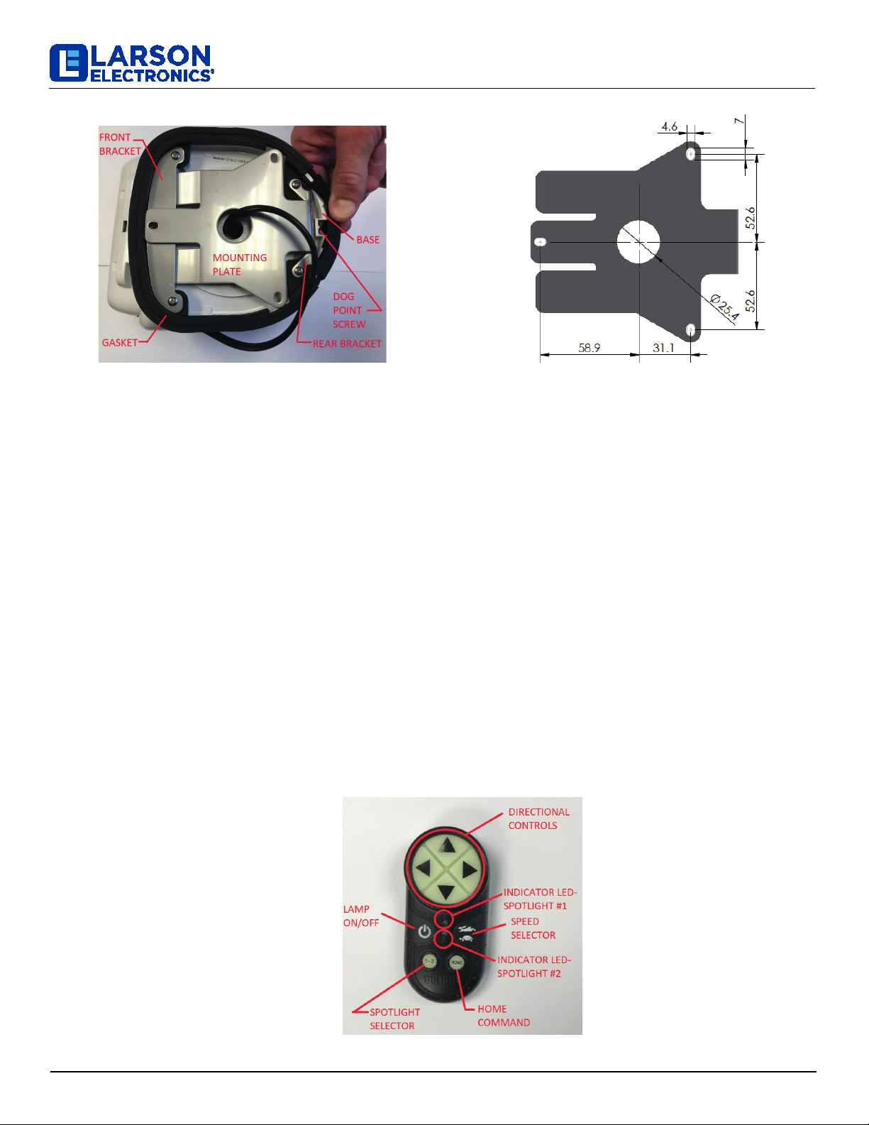
3. With the 4-way arrows on the remote, rotate or tilt your spotlight to the desired position. The camera system can be
rotated and tilted simultaneously. Depending upon condi-tions, the wireless remote may be used up to 80 feet from
the spotlight.
4. The speed of the rotation or tilt can be controlled by depressing the speed selection key one time and by depressing
it again to restore the original speed.
Quick Troubleshooting Guide
1. My camera system has NO function. Potential issues:
•Programming Issue (Wireless Remotes Only)
•Insufficient Power Supply
•Defective Batteries or Defective Wireless Remote
•Defective Receiver
Programming Issue- Our new camera system will not work out of the box. The remote MUST BE PAIRED TO THE
camera system before first use. The programming process for the camera system Handheld Wireless Remote Control
is different from our previous remotes.
1. Set remote for camera system #1. Depress any directional key to check. The indicator LED for spotlight #1 only
should be lit when you do this. If not, depress the spotlight selector button for five seconds to toggle to next
setting. (You may have to do this twice.)
2. Press and hold the on/off key and the speed selector key on the remote while simultaneously reconnecting power
to the spotlight. After three seconds the lamp will flash three times to confirm the pairing process was successful
Insufficient Power Supply- Verify your camera system is receiving adequate current.
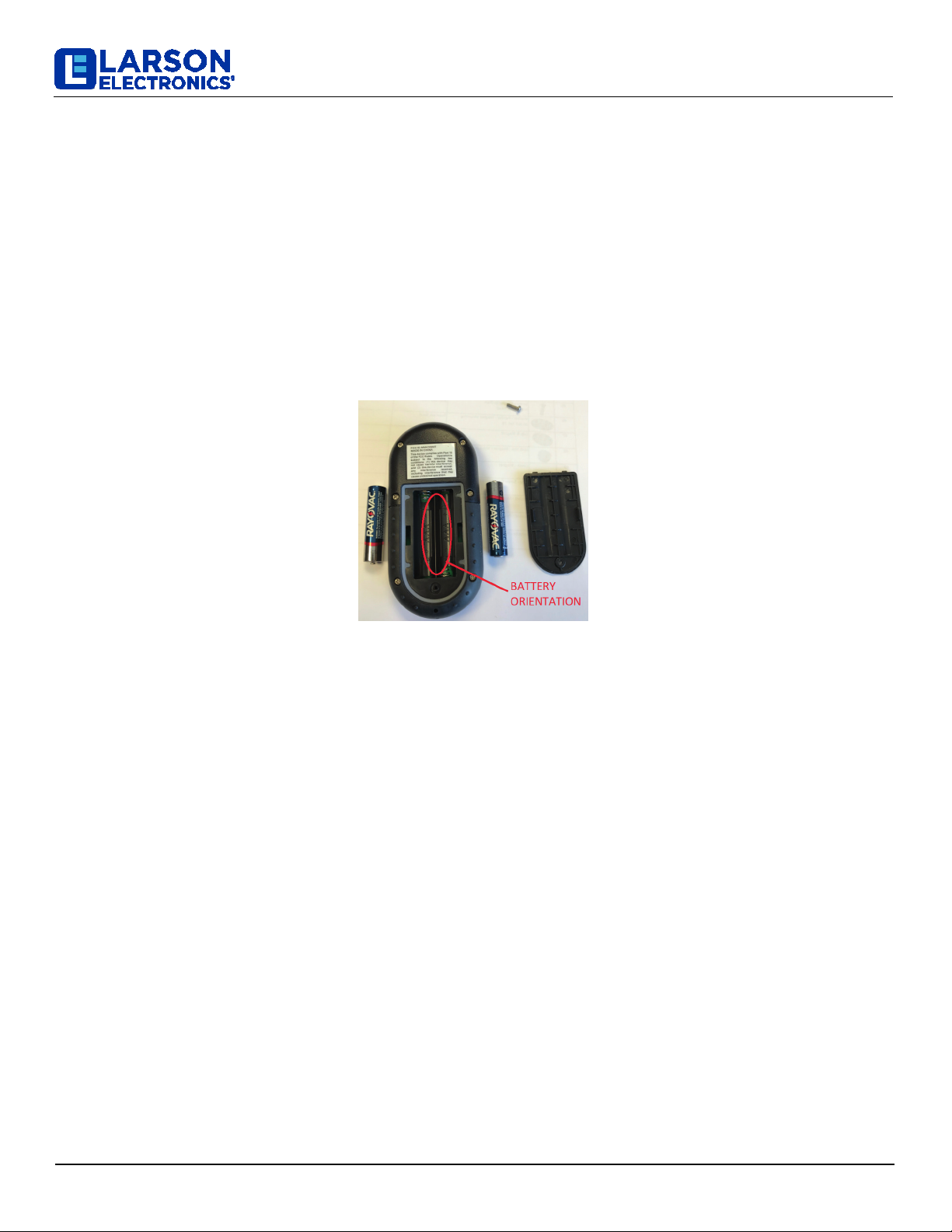
Defective Batteries or Defective Wireless Remote- There is a red LED light in the center of your wireless remote
control that should light up every time you depress a button. If there is no red LED light, start by replacing the batteries
in your remote control (2- AAA batteries). If this does not resolve the issue, the problem may be the remote control. If
available, use a different remote control to test the light. If a different remote is not available, please call our Customer
Service Department for assistance.
Defective Receiver- If you have done all of the above and your light still has no function; you may have a defective
receiver. Please call our Customer Service Department for further instructions.
My camera system will rotate left/right and up/down, but the camera isn't working. Potential Issues:
•Insufficient Power Supply
•Defective Receiver
Insufficient Power Supply- If the motors are operational, this is a sign that the unit is receiving adequate current, but
not enough current to illuminate the bulb. Verify your unit is receiving adequate current.
Defective Receiver- When pressing the power button on the remote control, do you hear a “clicking” sound? If so,
this means the receiver and the remote control are communicating, and the issue is most likely the bulb. (Please
note: in rare circumstances, a defective receiver can still produce a clicking sound.) If you do not hear anything when
you press the power button, the issue could be the receiver.
3. My camera works, but has rotation issues (no left/right, up/down, or both). Potential issues:
•Defective Motor
•Defective Receiver
•Defective Remote
RCL-336
Larson Electronics, LLC Phone: (800) 369-6671 Fax: (903) 498-3364 www.larsonelectronics.com 6of 10

Defective Motor- There are two motors in the camera system; one that controls horizontal movement and one that
controls vertical movement. If your camera will turn on but will not move L/R or U/D, you may have a defective motor.
Defective Receiver- If your camera works but rotates intermittently or not at all, your receiver may be the issue.
Defective Wireless Remote- There is a red LED light in the center of your wireless remote control that should light up
every time you depress a button. If it does not illuminate when depressing the left, right, up or down arrow you may
have a defective remote. If available, use a different wireless remote control to test the light. If a different remote is not
available, please call our Customer Service Department for assistance.
4. No Video Image
Make sure the power cables are connected properly
Make sure the video cables are connected properly
Double Image
Turn the power off and on and check to make sure the image is not frozen. Also check to see if clicking sounds are
coming from the thermal imager.
If the image is frozen or you do not hear a clicking sound, contact Larson Electronics.
Dithering or Fluctuating Image
Make sure the brackets holding the camera and mounted to the vehicle are tight and secure.
Dim Image
Make sure the video cables are connected properly.
BATTERY REPLACEMENT AND DISPOSAL
1. See instructions above for battery installation in the hand-held and dash mount remotes
2. Remove old batteries by gripping the positive end of each battery and lifting.
3. Batteries must be installed with proper polarity (positive and negative) as shown inside battery compartment.
4. Properly dispose of used batteries at your local recycling center.
SAFETY PRECAUTIONS
Your wireless camera system contains a radio transmitter and receiver operating at 2.4 GHz. Whenever the camera
is on, the internally mounted antennas send out and receive radio frequency (RF) energy.
Modern electronic equipment, i.e. personal medical devices such as pacemakers, hearing aids, etc. are shielded from
RF energy. However, RF energy may affect some electronic equip-ment.
Vehicle electronic systems may be affected by RF energy. Check with your vehicle manufacturer representative to be
sure that your thermal imaging camera system will not affect the electronic system of your vehicle.
RCL-336
Larson Electronics, LLC Phone: (800) 369-6671 Fax: (903) 498-3364 www.larsonelectronics.com 7of 10

⚠ WARNING: You risk death or serious injury to yourself and others if you do not follow the instruction highlighted by
the warning symbol. Failure to follow the specific warnings and instructions could result in personal injury, fire or
electrical shock.
⚠ WARNING: This light is for off-road and utility use only. It is not designed or approved for road use as a driving
light.
⚠ WARNING: The portable mount spotlight must be removed from the vehicle’s exterior while traveling at excessive
speeds and in strong wind conditions.
⚠ WARNING: The spotlight complies with Part.15 of the FCC Rules. Operation is subject to the follow-ing two
conditions: (1) This light and remote may not cause harmful interference, and (2) this light and remote must accept
any interference received, including interference that may cause undesired operation.
⚠ WARNING: Changes or modifications made by the user not expressly approved by Larson Electronics for
compliance could void the user’s authority to operate the equipment.
⚠ WARNING: This spotlight is not approved for use inside a vehicle or enclosure and power should be disconnected
prior to placing the light in such circumstance.
⚠ WARNING: This spotlight is not approved for underwater use.
⚠ WARNING: This spotlight is not approved for inverted mounting.
⚠ WARNING: This spotlight should not be turned on when snap on lens cover (rockguard) is attached.
⚠ WARNING: This spotlight may be damaged if operated in icing conditions.
Larson Electronics Contact
•Phone: 1-877-960-2536 (1-214-891-7441 for international inquiries)
•Email: [email protected]
•Fax: 1-903-498-3364
PRODUCT SAFETY WARNINGS/PROPER USE & MISUSE
RCL-336
Larson Electronics, LLC Phone: (800) 369-6671 Fax: (903) 498-3364 www.larsonelectronics.com 8of 10

RCL-336
7" Widescreen TFT/LCD Video Monitor
w/Headrest Shroud and Stand
Thank you for purchasing the TFT LCD color monitor. To enjoy the features
of this device and to ensure years of trouble-free operation, please read
this manual carefully and follow the instructions.
Front Panel
Remote control
Power ON/OFF
Analog variable increase
Menu button
V1/V2 conversion
Analog variable decrease
Switch for mode
1. Power ON/OFF
2. V1/V2 switch
3. Activation of menu indicator
4. Negative adjustment
1 2 3 4 5 6 7 8
5. Remote sensor
6. Positive adjustment
7. 16:9/4:3 display switch
8. Image rotation
Larson Electronics, LLC Phone: (800) 369-6671 Fax: (903) 498-3364 www.larsonelectronics.com 9of 10

RCL-336
Specification
Screen Size:
Resolution:
System:
Power source:
Power consumption:
Video Input:
Operating Temperature:
Storage Temperature:
Headrest bracket
Suitable for any kinds of car
seats. Easy and conveniently
installation without damage
to the seats. Length can be
adjusted(as Picture).
7 inch
1440xRGBx234
NTSC/PAL
DC 12V
<9W
Composition video signal
0°C ~ 60°C
-20°C ~ 80°C
Installation Diagram
(Yellow) Video 1 input
(Red) Audio right input
(White) Audio left input
(Yellow) Video 2 input
(Black) Grounding
(Red) Battery +12V
(Green) ACC Wire
1 x headrest shroud
1 x instruction manual
Accessories
1 x bracket
1 x remote control
2 x connection wire
Attentions:
1. When connect the electric power wires, you should make clear about the
positive and negative electrode ( the red one is positive and the black
is negative). If you wrongly connected the fuse in the filter box will be
broken protectively. Please replace the fuse in same parameter.
2. Because the LCD screen is the main component It should be paid
attention to be damp-proof.
3. The device must be installed firmly to prevent falling of device that will
possibly cause injury and device-broken.
4. The connecting-point of direct current (12V) should connect on the Main
line of storage battery as possible as it can , for keeping this device in
normal operation and be away from the large voltage drop influence.
5. There is high voltage cluster in this machine, if you are the professional
person, should never to take part the machine if malfunction and
contact the dealer in time.
Larson Electronics, LLC Phone: (800) 369-6671 Fax: (903) 498-3364 www.larsonelectronics.com 10of 10
Table of contents
Other Larson Electronics Thermal Camera manuals