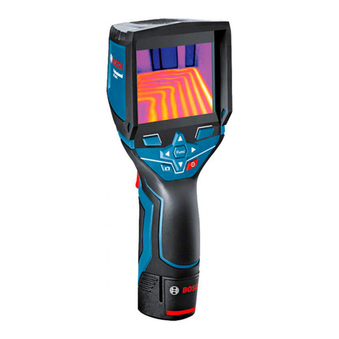
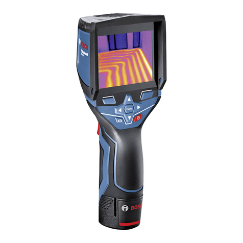
Bosch GTC 400 C Assembly instructions

IMPORTANT: IMPORTANT : IMPORTANTE:
Read Before Using Lire avant usage Leer antes de usar
Operating/Safety Instructions
Consignes de fonctionnement/sécurité
Instrucciones de funcionamiento y seguridad
GTC 400 C
1-877-BOSCH99 (1-877-267-2499) www.boschtools.com
Call Toll Free
for Consumer
Information
& Service Locations
Pour obtenir des informations
et les adresses de nos centres
de service après-vente,
appelez ce numéro gratuit
Llame gratis para
obtener información
para el consumidor y
ubicaciones de servicio
For English Version Version française Versión en español
See page 4 Voir page 20 Ver la página 36

-2-
XX.X°C
XX.X°C
XX.X°C
XX.X°C
XX.X°C
XX.XX.XXXX
XX.XX pm
XX.X
Mode Title
XX.X°C
XX.X°C
XX.X°C
XX.X°C
XX.X°C
XX.XX.XXXX
XX.XXpm
XX.X
Mode
Title
XX.X°C
XX.X°C
XX.X°C
XX.X°C
XX.X°C
XX.XX.XXXX
XX.XX pm
XX.X
Mode Title
12
3
4
5
13
12
11
14
15
16
17
20
10
19
18
7
6
8
9
a b edcf
g
i
kjlmn
h
GTC 400 C

-3-
BAT414 - BAT420
GBA12V30
GBA12V60
BC330
BC430
GAL 12V-20
21
22
1 600 A00 86E

-4-
Safety Symbols
The definitions below describe the level of severity for each signal word. Please read the manual and pay
attention to these symbols.
This is the safety alert symbol. It is used to alert you to potential personal
injury hazards. Obey all safety messages that follow this symbol to avoid
possible injury or death.
Read manual symbol - Alerts user to read manual.
WARNING indicates a hazardous situation which, if not avoided, could
result in death or serious injury.
This symbol designates that this thermal camera tool complies with
Part 15 of the FCC Rules.
Use and care
Use the correct tool for your application.
The correct tool will do the job better
and safer.
Protect the tool, particularly the area
around the camera and infrared lens, against
moisture and snow. The reception lens
could fog up and distort the measurements.
Incorrect settings on the tool and other
atmospheric influences may make the
measurements inaccurate. Objects could be
depicted hotter or colder, which may present
a danger if touched.
High temperature differences in a thermal
image may cause even high temperatures
to be shown in a colour associated with low
temperatures. Coming into contact with such
an area may cause burns.
Temperature measurements will only be
correct if the emissivity setting and the
emissivity of the object match. Objects could
be depicted hotter or colder in temperature
and/or colour, which may present a danger if
touched.
Do not use the tool if the switch does not turn
it on and off. Any tool that cannot be controlled
with the switch is dangerous and must be
repaired.
Store idle tool out of the reach of children and
do not allow persons unfamiliar with the tool or
these instructions to operate the tool. Tools are
dangerous in the hands of untrained users.
Maintain tools. Check for misalignment or
binding of moving parts, breakage of parts
and any other condition that may affect the
operation. If damaged, tool repaired before use.
Many accidents are caused by poorly maintained
tools.
Use the tool, accessories, etc., in accordance
with these instructions and in the manner
intended for the particular type of tool, taking
into account the working conditions and the
work to be performed. Use of the tool for
operations different from those intended could
result in a hazardous situation.
Battery tool use and care
Recharge only with the charger specified by
the manufacturer. A charger that is suitable for
one type of battery pack may create a risk of fire
when used with another battery pack.
General Safety Rules
Read all safety warnings, instructions, illustrations and specifications
provided with this tool. Failure to follow all instructions listed below may
result in electric shock, fire and/or serious injury.
SAVE ALL WARNINGS AND INSTRUCTIONS FOR FUTURE REFERENCE
The term “tool” in the warnings refers to your mains-operated (corded) tool or battery-operated
(cordless) tool.

-5-
Use tool only with specifically designated
battery packs. Use of any other battery packs may
create a risk of injury and fire.
When battery pack is not in use, keep it away
from other metal objects like paper clips, coins,
keys, nails, screws, or other small metal objects
that can make a connection from one terminal
to another. Shorting the battery terminals
together may cause burns or a fire.
Under abusive conditions, liquid may be ejected
from the battery; avoid contact. If contact
accidentally occurs, flush with water. If liquid
contacts eyes, additionally seek medical help.
Liquid ejected from the battery may cause
irritation or burns.
Do not use a battery pack or tool that is
damaged or modified. Damaged or modified
batteries may exhibit unpredictable behaviour
resulting in fire, EXPLOSION or risk of injury.
Do not expose a battery pack or tool to fire
or excessive temperature. Exposure to fire or
temperature above 265 °F (130 °C) may cause
explosion.
Follow all charging instructions and do not
charge the battery pack or tool outside the
temperature range specified in the instructions.
Charging improperly or at temperatures outside
the specified range may damage the BATTERY
and increase the risk of fire.
Disconnect the battery pack from the tool
before making any adjustments, changing
accessories, or storing the tool. Such preventive
safety measures reduce the risk of starting the
tool accidentally.
Do not modify or attempt to repair the tool
or the battery pack except as indicated in the
instructions for use and care.
Service
Have your tool serviced by a qualified repair
person using only identical replacement parts.
This will ensure that the safety of the tool is
maintained.
Develop a periodic maintenance schedule
for tool. When cleaning a tool be careful not
to disassemble any portion of the tool since
internal wires may be misplaced or pinched or
may be improperly mounted. Certain cleaning
agents such as gasoline, carbon tetrachloride,
ammonia, etc. may damage plastic parts.
Electrical safety
Batteries can explode or leak,
cause injury or fire. To reduce
this risk, always follow all instructions and warnings on
the battery label and package.
DO NOT expose the tool and battery to rain or wet
conditions. Water entering tool will increase the risk
of fire and personal injury.
DO NOT short any battery terminals.
DO NOT mix battery chemistries.
Dispose of or recycle batteries per local code.
DO NOT dispose of batteries in fire.
Keep batteries out of reach of children.
Remove batteries if the device will not be used for
several months.
Remove the batteries from the tool when
not using it for extended periods. When
storing for extended periods, the batteries
can corrode and self-discharge.
Caution! When using the tool with
Bluetooth®, interference with other devices
and systems, airplanes and medical devices
(e.g., cardiac pacemakers, hearing aids)
may occur. Also, the possibility of humans
and animals in direct vicinity being harmed
cannot be completely excluded. Do not use
the tool with Bluetooth® in the vicinity of
medical devices, petrol stations, chemical
plants, areas where there is danger of
explosion, and areas subject to blasting. Do
not use the tool with Bluetooth® in airplanes.
Avoid operation in direct vicinity of the body
over longer periods.
The tool is equipped with a radio interface.
Local operating restrictions, e.g. in airplanes
or hospitals, are to be observed.
Prevent unintentional starting. Ensure the
switch is in the off-position before inserting
batteries. Accidental energizing tool that have the
switch on invites accidents.
Chemical Burn Hazard. Keep
lithium button/coin batteries
away from children. This product contains a
lithium button/coin cell battery. If a new or used
lithium button/coin cell battery is swallowed or
enters the body, it can cause severe internal
burns and can lead to death in as little as 2 hours.
Always completely secure the battery
compartment. If the battery compartment does
not close securely, stop using the product,
remove the batteries, and keep it away from
children. If you think batteries might have been
swallowed or placed inside any part of the body,
seek immediate medical attention.
-6-
This thermal imaging camera is designed for
the contactless measurement of surface
temperatures.
The displayed thermal image shows the
temperature distribution of the area captured
by the infrared lens and therefore enables
temperature deviations to be depicted in different
colors.
When used correctly, this makes it possible to
examine areas and objects in a contactless
manner for temperature differences and
discrepancies in order to make components and/
or any weaknesses visible, including:
– Thermal insulation and other types of insulation
(e.g. locating thermal bridges)
– Active heating and hot water pipes (e.g.
underfloor heating) in floors and walls
– Overheated electrical components (e.g. fuses
or terminals)
– Machine parts (e.g. overheating due to faulty
ball bearings)
The tool must not be used for temperature
measurement on persons and animals or for
other medical purposes.
The tool is not suitable for surface temperature
measurement of gases or liquids.
Intended Use
The manufacturer is not responsible
for radio interference caused by
unauthorized modifications to this
equipment. Such modifications could void the
user’s authority to operate the equipment.
This device complies with Part 15 of the FCC
Rules. Operation is subject to the following two
conditions:
1)This device may not cause harmful interfer-
ence, and
2)This device must accept any interference re-
ceived, including interference that may cause
undesired operation.
NOTE! This equipment has been tested and
found to comply with the limits for a Class B
digital devices, pursuant to Part 15 of the FCC
rules. These limits are designed to provide rea-
sonable protection against harmful interference
in a residential installation. This equipment gen-
erates uses and can radiate radio frequency en-
ergy and, if not installed and used in accordance
with the instructions, may cause harmful interfer-
ence to radio communications. However, there
is no guarantee that interference will not occur
in a particular installation. If this equipment does
cause harmful interference to radio or television
reception, which can be determined by turning
the equipment off and on, the user is encouraged
to try to correct the interference by one or more
of the following measures:
• Reorientorrelocatethereceivingantenna.
• Increase the separation between the equip-
ment and receiver.
• Connecttheequipmentintoanoutletonacir-
cuit different from that to which the receiver is
connected.
• Consultthedealeroranexperiencedradio/TV
technician for help.
“Exposure to Radio Frequency (RF) Signals: The
wireless device is a radio transmitter and receiv-
er. It is designed and manufactured not to exceed
the emission limit for exposure to radio frequency
(RF) energy set by the Ministry of Health (Cana-
da), Safety Code 6. These limits are part of com-
prehensive guidelines and established permitted
levels of RF energy for the general population.
FCC Caution
This device complies with Industry Canada’s
licence-exempt RSSs. Operation is subject to the
following two conditions:
(1) This device may not cause interference; and
(2) This device must accept any interference,
including interference that may cause undesired
operation of the device.
Industry Canada (IC)

-7-
The numbering of the product features shown refers to the illustration of the tool on the
graphic page.
1Protective cap for visual camera and
infrared sensor
2Serial number
3Cover, micro USB port
4Micro USB port
5Up arrow button [ ]
6Measuring functions button [Func]
7Switching temperature scale between
automatic and fixed/right-hand function
button
8Right-hand arrow button [ ]
9On/Off button [ ]
10 Down arrow button [ ]
11 Save button
12 Left-hand arrow button [ ]
13 Gallery button/left-hand function button
14 Display
15 Visual camera
16 Infrared sensor area
17 Freeze measurement/continue
measuring button
18 Battery port
19 Release button for battery pack
20 Battery pack*
21 Micro USB cable
22 Protective pouch*
Display Elements
aDate/time
bMeasuring function
cEmissivity display
dIndicator for Bluetooth® connection
eWiFi switched on/off indicator
fCharge-control indicator
gDisplay of maximum surface temperature
in the measurement range
hScale
iDisplay of minimum surface temperature
in the measurement range
jScale lock symbol
kHotspot display (example)
lCrosshairs with temperature display
mColdspot display (example)
nGallery symbol
*The accessories illustrated or described are not included as standard delivery.
Features

-8-
Technical Data
Thermal imaging camera GTC 400 C
Article number 3 601 K83 1..
Resolution of infrared sensor 160 x 120
Thermal sensitivity <50mK
Spectral range 8–14 μm
Field of view (FOV) 53 x 43°
Focus distance ≥1 ft (≥0.3m)
Focus Fixed
Surface temperature measurement range 14...+752 °F (–10...+400 °C)
Measuring accuracy (typical) Surface temperature1)
–10...+10 °C
10...100 °C
>+100 °C
5.4 °F (3 °C)
5.4 °F (3 °C)
3 %
Display type TFT
Display size 3.5”
Display resolution 320 x 240
Image format .jpg
Images saved per saving process 1 x thermal image (screenshot)
1 x real visual image incl. temperature
values (metadata)
Number of images in internal image
memory (typical)
500
Integrated visual camera •
Battery / Charger list
–Rechargeable Batteries (Bosch 10.8 V/12 V – Max lithium-ion pack)
–Chargers
BAT414 2.0 Ah, BAT420 4.0 Ah
GBA12V30 3.0 Ah, GBA12V60 6.0 Ah
BC330, BC430
GAX1218V-30, GAL 12V-20
Battery life
10.8 V/12 V - Max
5.0 h
USB port 1.1
Blue Hound Bluetooth® module power supply
– Button cell
– Battery service life, approx.
CR2450 (3 V lithium battery)
60 months
Bluetooth® Bluetooth® 4.2 (Low Energy)
Max. Bluetooth® transmission power 3.2mW
Frequency band Bluetooth® 2.402 – 2.480 GHz
Wireless connectivity WiFi
Max. WiFi transmission power 30mW

-9-
Thermal imaging camera GTC 400 C
WiFi operating frequency range 2.400–2.483 GHz
Weight according to EPTA-Procedure 01:2014 0.54 kg
Dimensions (length x width x height) 9.2” x 3.7” x 2.5” (233 x 95 x 63 mm)
Degree of protection (excluding battery compartment) IP 53
Permitted environmental conditions
– Charging temperature
– Operating temperature2)
– Storage temperature
– Relative humidity (non-condensing)
32....+113 °F (0...+45 °C)
14....+113 °F (–10...+45 °C)
-4....+158 °F (–20...+70 °C)
20... 80 %
The tool can be clearly identified with the serial number 2on the type plate.
1) at an ambient temperature of 20–23 °C and an emissivity of >0.999, measuring distance: 0.3m,
operating time: >5 min.
2) limited performance at temperatures <0 °C.
Technical data determined with battery from delivery scope.

-10-
Infrared heat radiation
Infrared heat radiation is electromagnetic
radiation emitted by every body. The amount
of radiation depends on the temperature and
the emissivity degree of the body.
Emissivity Degree
The emissivity degree of an object depends on
the material and the structure of its surface.
It states how much infrared heat radiation the
object emits compared to an ideal heat emitter
(black body, emissivity degree = 1).
Thermal Bridge
A thermal bridge is an object that undesirably
transmits heat outwards or inwards, therefore
differing significantly from the temperature
of the rest of a wall or from the desired
temperature of a wall.
As the surface temperature at thermal bridges
is lower than in the rest of the room, the risk of
mold increases significantly at these locations.
Reflected temperature/reflectivity of an
object
The reflected temperature is the thermal
radiation that is not emitted by the object
itself. Depending on the structure and
material, background radiation is reflected in
the object to be measured, therefore distorting
the actual temperature result.
Distance from the object
The distance between the object being
measured and the measuring tool influences
the captured area size per pixel. You can
capture increasingly large objects as the
distance from the object becomes greater.
Distance (m) Size of infrared
pixels (mm) Infrared range
width x height (m)
0.5 3–0.5 x 0.4
1 6 –1 x 0.75
212 2.05 x 1.5
530 5.1 x 3.8
Blue Hound
The built-in Bluetooth® Low Energy Module
enables you to personalize and check the
status of your measuring tool, as well as
transfer settings and data using Bluetooth®
wireless technology.
Blue Hound Bluetooth® module power supply
The measuring tool is fitted with a button cell
so that it can still be detected by a mobile
device using Blue Hound without having a
battery pack 20.
You can find further information directly in the
app from Bosch.
Data Transmission
You can switch the Blue Hound Bluetooth®
module on and off in the tool settings. It then
emits a continuous signal.
The transmission interval of the module
is eight seconds. Depending on ambient
conditions, up to three transmission intervals
may be required before the tool is detected.
Note: Switch Blue Hound off in areas where
the transmission of radio waves is prohibited,
for example on airplanes.
Registering and setting up the app/web-
based application
Before you can use Blue Hound, you need to
register online.
To do this, open the website https://www.
boschtracking.com/#/login and register. After
registration is complete, you will receive your
access information.
Download the app Blue Hound from the
relevant app store (Apple App Store, Google
Play Store) or access the web application
at https://www.boschtracking.com/#/login,
where you can log in using your access details.
You can now create and manage your inventory
using the app/web-based application.
Note: First, complete the tutorial for the app/
web-based application.
This will provide you with a better overview of
the procedure for creating the inventory and
using the software.
Definitions

-11-
Preparation
Power Supply
The tool can be operated using a Bosch Li-ion
rechargeable battery.
Operation with Battery Pack (see figure C)
Use only Bosch
rechargeable lithium-ion
battery packs listed in the technical data
section of this manual. Use of other battery
packs may increase the risk of fire, personal
injury and property damage.
Remove the batteries from
the tool when not using it
for extended periods. When storing for
extended periods, the batteries can corrode and
self-discharge.
Note: The battery pack is supplied partially
charged. To ensure full capacity of the battery
pack, completely charge the battery pack in
the battery charger before using for the first
time.
Use only Bosch chargers
listed in the technical data
section of this manual. Use of other chargers
may increase the risk of fire, personal injury and
property damage.
The lithium-ion battery pack can be charged
at any time without reducing its service life.
Interrupting the charging procedure does not
damage the battery pack.
The lithium-ion battery is protected against
deep discharge by the Electronic Cell Protec-
tion (ECP). A protective circuit switches the
laser level off when the battery is drained.
•Following the automatic shut off of the tool,
do not continue to press the On/Off button.
The battery can be damaged.
To insert the charged battery pack 20, slide
it into the battery port 18 until you feel it lock
into position. Do not use force.
To remove the battery pack 20, press the
unlocking buttons 19 and pull the battery pack
out of the battery port 18. Do not use force.
Battery Status Indicator
The battery status indicator fon the display
shows the charging state of the batteries or
battery pack 20.
Indication Capacity
>2/3
≤2/3
≤1/3
≤10%
Changing the Batteries or Battery Pack

-12-
Operation
•Protect the measuring tool against moisture
and direct sun light.
•Do not subject the measuring tool to
extreme temperatures or variations in
temperature. As an example, do not leave
it in vehicles for a long time. In case of
large variations in temperature, allow the
measuring tool to adjust to the ambient
temperature before putting it into operation.
In case of extreme temperatures or variations
in temperature, the accuracy of the
measuring tool can be impaired.
•Make sure that the tool is correctly
acclimatized. In the event of severe
temperature fluctuations or environmental
conditions which vary to a large degree, the
measurement accuracy of the measuring tool
may be impaired until it is fully acclimatized
again.
•Avoid hard knocks to the tool or dropping
it. After severe external influences and in the
event of abnormalities in the functionality,
you should have the measuring tool checked
by an authorized Bosch after-sales service
agent.
Initial Operation
Switching On and Off
To take a measurement, fold the protective
cap 1upwards. Make sure that the infrared
measuring area is not closed off or covered
while working.
To switch on the tool, press the On/Off button
9. A start sequence will appear in the display
14. After the start sequence, the measuring
tool will immediately begin to measure and will
measure continuously until it is switched off.
Note: In the first few minutes, the measuring
tool may self-calibrate several times, as the
sensor temperature and ambient temperature
have not yet been brought into line.
Performing calibration again enables precise
measurement. The thermal image freezes
briefly during calibration.
To switch off the tool, press the On/Off
button again. The measuring tool saves all
settings and then switches itself off. Close the
protective cap 1to transport the measuring
tool safely.
In the “Settings” menu, you can choose
whether and after how much time the
measuring tool automatically switches off (see
“Switch-off time”, page 15).
If the battery or the measuring tool is not
within the operating temperature range stated
in the Technical Data, the measuring tool will
shut down automatically after a brief warning
(see “Troubleshooting – Causes and Corrective
Measures”, page 18). Allow the measuring tool
to reach to the correct temperature and then
switch it back on.
To save energy, only switch the measuring tool
on when you are using it.
Preparing for Measurement
Setting the Emissivity Degree for Surface-
temperature Measurements
The emissivity degree of an object depends on
the material and the structure of its surface.
It indicates whether an object (in comparison
with other objects with the same temperature)
emits much or little infrared heat radiation.
To determine the surface temperature, the
tool performs a contactless measurement of
the natural infrared thermal radiation emitted
by the object at which the tool is aimed. To
ensure correct measurement, the emissivity
setting on the measuring tool must be checked
before every measurement and adapted to
the measuring object if necessary.
You can select one of the preset emissivity
levels or enter an exact numerical value.
Adjust the required emissivity using the
“Measurement” >“Emissivity” menu (see
page 15).
Temperature
measurements will only be
correct if the emissivity setting and the
emissivity of the object match.
Differences in color may be caused by different
temperatures and/or different emissivity levels.
If the emissivity levels are very different, the
depicted temperature differences may differ
considerably from the actual temperature
differences.
If there are multiple objects made of different
materials or that have different structures
in the measurement range, the displayed
temperature values are only conclusive for
the objects that match the emissivity setting.

-13-
For all other objects (with different emissivity
levels), the displayed color differences can
be used as an indication of temperature
relationships.
Material Emissivity
32 ºF to 212 ºF (0 ºC to 100 ºC)
Concrete 0.93
Plaster/mortar 0.93
Roofing tiles 0.93
Roofing felt 0.93
Radiator paint 0.93
Wood 0.91
Linoleum 0.88
Paper 0.89
Notes on the Measuring Conditions
Highly reflective or shiny surfaces (e.g. shiny
tiles or polished metals) may distort or impair
the results shown. If necessary, mask the
surface to be measured with a dark, matt
adhesive tape that conducts heat well. Allow
the tape to acclimatize briefly on the surface.
Make sure that a favorable measuring angle
is used on reflective surfaces in order to
ensure that the thermal radiation reflected
by other objects does not distort the result.
For example, the reflection of your own body
heat may interfere with the measurement
when measuring head-on from a perpendicular
position. On a level surface, the outline and
temperature of your body could therefore be
displayed (reflected value), and these values
do not correspond to the actual temperature
of the measured surface (emitted value or
real value of the surface). Measuring through
transparent materials (e.g. glass or transparent
plastics) is fundamentally not possible.
The accuracy and reliability of the measuring
results increase with better and more stable
measuring conditions.
Infrared temperature measurement is impaired
by smoke, vapor/ high air humidity or dusty air.
Information for achieving improved
measurement accuracy:
– Get as close as possible to the measuring
object to minimize interfering factors
between you and the surface to be
measured.
– Ventilate indoor areas prior to measurement,
especially when the air is contaminated or
extremely steamy. After ventilating, allow
the room to acclimatize for a while until the
usual temperature has been reached again.
Assigning temperatures on the basis
of the scale
21,8 °C
32,5 °C
A scale is shown on the right-hand
side of the display. The values at the
top and bottom end are oriented to
the maximum and minimum
temperature recorded in the thermal
image. Colors are assigned to
temperature values with a uniform
distribution in the image (linearly).
Different shades can therefore be
used to assign temperatures within
these two limit values. For example,
a temperature that is exactly
between the maximum and minimum
value can be assigned to the center
color range of the scale.
To determine the temperature of a specific
area, move the measuring tool so that the
crosshairs with temperature display lare
aimed at the required point or area.
In the automatic setting, the color spectrum
of the scale is always distributed linearly (=
uniformly) across the entire measurement
range between the maximum and minimum
temperatures.
The thermal imaging camera displays all
measured temperatures in the measurement
range in relation to one another. If heat is
displayed as blue in the color palette in an
area, for example in a color representation,
this means that the blue areas are among
the colder measured values in the current
measurement range. However, these areas
may be in a temperature range that could
cause injuries in certain circumstances. You
should therefore always note the temperatures
displayed on the scale or at the crosshairs
themselves.

-14-
Functions
Adjusting the color display
Depending on the measurement conditions,
different color palettes can make it easier to
analyze the thermal image and show objects or
circumstances more clearly in the display. This
does not affect the measured temperatures.
Only the way in which the temperature values
are shown changes.
To change the color palette, remain in
measuring mode and press the right-hand 8or
left-hand 12 arrow button.
Superimposition of thermal image
and real image
For improved orientation (= local assignment
of the thermal image displayed), with matched
temperature ranges, a visual real image can
additionally be inserted.
Note: The superimposition of the real image
and thermal image is accurate at a distance
of 1.08 ft (0.55 m). If the tool is closer to or
further away from the object being measured,
this may result in misalignment of the real
image and thermal image.
The thermal imaging camera offers you the
following options:
– Complete infrared image
Only the thermal image is displayed.
– Image in image
The thermal image displayed is cropped
and the surrounding area is shown as a
real image. This setting improves the local
assignment of the measurement range.
– Transparency
The thermal image displayed is placed on
top of the real image in such a way that it is
slightly transparent. This enables improved
detection of objects.
You can adjust the setting by pressing the up 5
or down 10 arrow buttons.
Fixing the scale
The color distribution in the thermal image
is adjusted automatically but can be fixed
by pressing the right-hand function button
7. This enables a comparison to be made
between thermal images taken under different
temperature conditions (e.g. when checking
several rooms for thermal bridges).
To switch the scale back to automatic, press
the right-hand function button 7again.
The temperatures are now dynamic again
and adapt to the measured minimum and
maximum values.
Measuring functions
To call up further functions which may be
helpful for the display, press the “Func” button
6. Use the right-hand/left-hand buttons to
navigate through the displayed options to
select a function. Select a function and press
the “Func” button 6again.
The following measuring functions are
available:
– “Automatic”
Colors are distributed automatically in the
thermal image
– “Heat detector”
Only the warmer temperatures in the
measurement range are displayed as a
thermal image in this measuring function.
The area outside these warmer temperatures
is displayed in greyscale as a real image so that
colored objects are not wrongly associated
with temperatures (e.g. red cable in the
control cabinet when looking for overheated
components). Adjust the scale using the up 5
and down 10 buttons. This expands or reduces
the temperature range shown.
The tool continues to measure minimum and
maximum temperatures and displays these
at the ends of the scale. You can, however,
control which temperature range is shown in
color as a thermal image.
– “Cold detector”
Only the colder temperatures in the
measurement range are displayed as a
thermal image in this measuring function.
The area outside these colder temperatures
is displayed in greyscale as a real image
so that colored objects are not wrongly
associated with temperatures (e.g. blue

-15-
window frame when looking for faulty
insulation). Adjust the scale using the up
5and down 10 buttons. This expands or
reduces the temperature range shown. The
tool continues to measure minimum and
maximum temperatures and displays these
at the ends of the scale. You can, however,
control which temperature range is shown in
colour as a thermal image.
– “Manual”
If greatly deviating temperatures are
measured in the thermal image (e.g. radiator
as a hot object when searching for thermal
bridges), the available colors are distributed
among a large number of temperature values
in the range between the maximum and
the minimum temperature. This can result
in a situation where subtle temperature
differences can no longer be shown in detail.
To obtain a detailed depiction of the focus
temperature, switch to “Manual” mode
and set the maximum and the minimum
temperature. Doing this enables you to set
the temperature range that is relevant to you
and in which you would like to detect subtle
differences. The Reset setting automatically
readjusts the scale to the measured values
in the infrared sensor’s field of view.
Main Menu
To access the main menu, press the “Func”
button 6to call up the measuring functions.
Now press the right-hand function button 7.
– “Measurement”
– “Emissivity” c:
A selection of saved emissivity levels is
available for some of the most common
materials. Select the appropriate material
in the “Material” menu item. The
corresponding emissivity is displayed
in the line below. If you know the exact
emissivity of the object to be measured,
you can also set it as a numerical value in
the “Emissivity” menu item.
– “Reflected temperature”:
Setting this parameter improves the
accuracy of measuring results, especially
with low-emissivity (= high-reflection)
materials. The reflected temperature
normally corresponds to the ambient
temperature. If there are objects with
greatly deviating temperatures close to
highly reflective objects which could
affect the measurement, this value should
be adjusted.
– “Display”
– “Hotspot” k: “ON/OFF”
In this function, the hottest point (=
measuring pixel) in the measurement
range is automatically highlighted by red
crosshairs in the thermal image. This can
help you to detect a critical point, e.g.
to locate a loose terminal in the control
cabinet.
– “Cold spot” m: “ON/OFF”
The coldest point (= measuring pixel) in
the measurement range is automatically
highlighted by blue crosshairs in the
thermal image. This can help you to detect
a critical point, e.g. to locate a leak in
insulation.
– “Crosshairs” l: “ON/OFF”
The crosshairs are displayed in the centre
of the thermal image and show you the
measured temperature value at this point.
– “Scale” h: “ON/OFF”
– “WiFi”: “ON/OFF”
(see “Data Transmission”, page 16)
– “Blue Hound”: “ON/OFF”
(see “Blue Hound”, page 10)
– “Tool”
– “Language”
Under this menu item, you can change the
language for all displays.
– “Time & Date” a
To change the date and time in the display,
open the “Time & Date” submenu. In
this submenu you can also change the
date and time format. To exit the “Time &
Date” submenu, press either the left-hand
function button 13 under the tick symbol to
save the settings or the right-hand function
button 7under the cross symbol to discard
the changes.
– “Audio signals”: “ON/OFF”
Under this menu item, you can switch the
audio signals on or off.
– “Switch-off time”
Under this menu item, you can select
the time interval after which the tool will
automatically switch off if no buttons

-16-
are pressed. You can also deactivate the
automatic switch-off by selecting the
“Never” setting.
– “Delete all images”
Under this menu item, you can delete all
the files in the internal memory at once.
Press the right-hand arrow button 8for
“more ...” to enter the submenu. Then
press either the left-hand function button
13 under the tick symbol to delete all files,
or the right-hand function button 7under
the cross symbol to cancel the operation.
– “Tool information”
Under this menu item, you can access
information about the tool. There you can
find the serial number of the tool and the
installed software version.
You can also press button 17 to exit any menu
and return to the standard display screen.
Documenting measurements
Saving measurements
The tool begins to take measurements as soon
as it is switched on and does so continuously
until it is switched off.
To save an image, point the camera at the
desired measuring object and press the
“Save” button 11. The image is saved in the
camera’s internal memory. Alternatively,
press the “Freeze measurement” button 17.
The measurement is frozen and shown in the
display. This enables you to take as much time
as you need to look at the image. If you do not
wish to save the frozen image, press button
17 to return to measuring mode. If you wish
to save the image in the camera’s internal
memory, press the “Save” button 11.
Calling up saved images
Proceed as follows to call up saved thermal
images:
– Press the left-hand function button 13. The
most recently saved photo now appears in
the display.
– Press the right-hand 8or left-hand 12 arrow
button to switch between the saved thermal
images.
Deleting saved images
Go to the gallery view to delete individual
thermal images:
– Press the right-hand function button 7under
the waste paper basket symbol.
– Confirm the operation by pressing the left-
hand function button 13 or terminate the
deletion process by pressing the right-hand
function button 7under the cancel symbol.
Delete all images
In the “Delete all images” menu, you can
delete all the files in the internal memory at
once.
Press the “Func” 6 button to call up the
measuring functions. Now press the right-hand
function button 7and select “Tool” > “Delete
all images”. Press the right-hand arrow button
8to enter the submenu. Then press either the
lefthand function button 13 under the tick
symbol to delete all files, or the right-hand
function button 7under the cross symbol to
cancel the operation.
Data Transmission
Data Transmission via USB Interface
Open the cover on the micro USB port 3.
Connect the micro USB port on the tool to
your PC or laptop using the micro USB cable
provided.
Now press button 9to switch on the thermal
imaging camera.
Open the file browser and select the “BOSCH
GTC 400 C” drive. The saved JPG files can be
copied, moved to your computer or deleted
from the internal memory of the tool.
As soon as you have ended the required
operation, disconnect the drive following the
standard procedure and then use button 9to
switch the thermal imaging camera off again.
Remove the micro USB cable during the
measurement operation and close the cover 3.
Attention: Always disconnect the drive from
your operating system first (eject drive), as
failure to do so may damage the thermal
imaging camera’s internal memory.
Always keep the cover of the USB interface
closed so that dust and splashes cannot enter
the housing.

-17-
Note: Only connect the tool to a PC or
notebook. The tool could be damaged if you
connect it to a different device.
Note: The micro USB interface can only be
used for data transmission – it is not suitable
for charging batteries.
Post-editing the thermal images
You can post-edit the saved thermal images
on your computer if it uses a Windows
operating system. To do so, download the GTC
Transfer software from the product page for
the thermal imaging camera at www.bosch-
professional.com/gtc.
Data transmission via WiFi
The tool is equipped with a WiFi module which
enables the saved images to be wirelessly
transmitted from your thermal imaging camera
to a mobile device.
The Bosch Thermal App is required as the
software interface for this. You can download
this from the store for your end device type:
In addition to wirelessly transmitting your
images, the Bosch Thermal App makes it
possible for you to use an extended range
of functions and facilitates post-editing and
forwarding of measured data (for example
via e-mail). Information about system
requirements for a WiFi connection can be
found on the Bosch website at “www.bosch-
professional.com/gtcthermalapp”.
To activate or deactivate the WiFi connection
on the tool, call up the main menu, use the
buttons to select “WiFi” and activate or
deactivate it. e will appear on the display.
Ensure that the WiFi interface is activated on
your mobile device.
The connection between the mobile device
and the tool can be established after the
Bosch application has been started (if WiFi
modules are activated). To do this, follow the
instructions in the Bosch Application.

-18-
Check the tool each time
before use. In case of visible
damage or loose components inside the
measuring tool, safe function can no longer be
ensured.
Keep the tool clean at all times.
Do not immerse the tool into water or
other fluids.
Do attempt to remove dust from the sensor,
camera or reception lens using pointing
objects, and do not wipe over the camera and
reception lens (risk of scratching).
If the tool should fail despite the care taken in
manufacturing and testing procedures, repair
should be carried out by an authorized after-
sales service center for Bosch power tools. Do
not open the measuring tool yourself.
In all correspondence and spare parts orders,
please always include the 10-digit article
number given on the type plate of the tool.
ENVIRONMENT PROTECTION
Recycle raw materials & batteries instead of
disposing of waste. The unit,
accessories, packaging & used
batteries should be sorted for
environmentally friendly recycling
in accordance with the latest
regulations.
Maintenance and Service
Troubleshooting – Causes and Corrective Measures
Error Cause Corrective Measure
Measuring tool cannot be switched on. Battery pack or batteries
empty
Charge the battery pack or change the batteries.
Allowthe batterytoreach thecorrecttemperature
or change it.
Battery too warm or
too cold
Measuring tool too warm
or too cold
Allow the measuring tool to reach the correct
temperature.
Format the internal memory by deleting all images
(see “Delete all images”, page 16). If the problem
persists, send the measuring tool to an authorized
Bosch after-sales service agent.
Image memory full If required, transfer the images to another storage
medium (e.g. computer or notebook). Then delete
the images in the internal memory.
Send the measuring tool to an authorized BoschMeasuring tool is fault
after-sales service agent.
Measuring tool cannot be connected to a
computer.
Measuring tool not recog-
nized by computer
Check whether the driver on your computer is up to
date. It may be necessary to have a newer operating
system version on your computer.
Micro USB connection or
micro USB cable fault
Check whether the measuring tool can be connected
to a different computer. If not, send the measuring
tool to an authorized Bosch after-sales service agent.
Image memory fault
In the event of a fault, the tool will restart and can then continue to be used. If the fault
persists, the following overview may help you.

-19-
LIMITED WARRANTY OF BOSCH LASER AND MEASURING TOOL PRODUCTS
Robert Bosch Tool Corporation (“Seller”) warrants to the original purchaser only, that all Bosch lasers and
measuring tools will be free from defects in material or workmanship for a period of one (1) year from date
of purchase. Bosch will extend warranty coverage to two (2) years when you register your product within
eight (8) weeks after date of purchase. Product registration card must be complete and mailed to Bosch
(postmarked within eight weeks after date of purchase), or you may register on-line at www.boschtools.
com/Service/ProductRegistration. If you choose not to register your product, a one (1) year limited
warranty will apply to your product.
30 Day Money Back Refund or Replacement -
If you are not completely satisfied with the performance of your laser and measuring tools, for any
reason, you can return it to your Bosch dealer within 30 days of the date of purchase for a full refund
or replacement. To obtain this 30-Day Refund or Replacement, your return must be accompanied by
the original receipt for purchase of the laser or optical instrument product. A maximum of 2 returns per
customer will be permitted.
SELLER’SSOLEOBLIGATIONANDYOUREXCLUSIVEREMEDYunderthisLimitedWarrantyand,to
the extent permitted by law, any warranty or condition implied by law, shall be the repair or replacement
of parts, without charge, which are defective in material or workmanship and which have not been
misused, carelessly handled, or misrepaired by persons other than Seller or Authorized Service Center.
To make a claim under this Limited Warranty, you must return the complete Bosch laser or measuring
tool, transportation prepaid, to any BOSCH Factory Service Center or Authorized Service Center. Please
include a dated proof of purchase with your tool. For locations of nearby service centers, please use our
on-line service locator or call 1-877-267-2499.
THIS WARRANTY PROGRAM DOES NOT APPLY TO TRIPODS AND RODS. Robert Bosch Tool
Corporation (“Seller”) warrants tripods and leveling rods for a period of one (1) year from date of purchase.
THIS LIMITED WARRANTY DOES NOT APPLY TO OTHER ACCESSORY ITEMS AND RELATED
ITEMS.THESEITEMSRECEIVEA90DAYLIMITEDWARRANTY.
To make a claim under this Limited Warranty, you must return the complete product, transportation
prepaid. For details to make a claim under this Limited Warranty please visit www.boschtools.com or call
1-877-267-2499.
ANY IMPLIED WARRANTIES SHALL BE LIMITED IN DURATION TO ONE YEAR FROM DATE OF
PURCHASE.SOMESTATESINTHEU.S.,ANDSOMECANADIANPROVINCESDONOTALLOW
LIMITATIONSONHOWLONGANIMPLIEDWARRANTYLASTS,SOTHEABOVELIMITATIONMAY
NOT APPLY TO YOU.
INNOEVENTSHALLSELLERBELIABLEFORANYINCIDENTALORCONSEQUENTIALDAMAGES
(INCLUDING BUT NOT LIMITED TO LIABILITY FOR LOSS OF PROFITS) ARISING FROM THE SALE
ORUSEOFTHISPRODUCT.SOMESTATESINTHEU.S.,ANDSOMECANADIANPROVINCESDO
NOTALLOWTHEEXCLUSIONORLIMITATIONOFINCIDENTALORCONSEQUENTIALDAMAGES,
SOTHEABOVELIMITATIONMAYNOTAPPLYTOYOU.
THISLIMITEDWARRANTYGIVESYOUSPECIFICLEGALRIGHTS,ANDYOUMAYALSOHAVE
OTHERRIGHTSWHICHVARYFROMSTATETOSTATEINTHEU.S.,ORPROVINCETOPROVINCE
IN CANADAAND FROM COUNTRY TO COUNTRY.
THIS LIMITED WARRANTY APPLIES ONLY TO PRODUCTS SOLD WITHIN THE UNITED STATES OF
AMERICA,CANADAANDTHECOMMONWEALTHOFPUERTORICO.FORWARRANTYCOVERAGE
WITHIN OTHER COUNTRIES, CONTACT YOUR LOCAL BOSCH DEALER OR IMPORTER.

-20-
Symboles relatifs à la sécurité
Les définitions ci-dessous décrivent le niveau de gravité pour chaque terme signalant un danger. Veuillez lire le mode d’emploi
et lire la signification de ces symboles.
C’est le symbole d’alerte relatif à la sécurité. Il est utilisé pour vous avertir de l’existence
possible d’un danger delésion corporelle. Obéissezà tous les messagesrelatifs à lasécurité
qui suivent ce symbole pour éviter tout risque de blessure ou même de mort.
Symbole de lecture du mode d’emploi - Alerte l’utilisateur pour lire le mode d’emploi.
AVERTISSEMENT indique une situation dangereuse qui, si elle n’est pas évitée, pourrait
causer la mort d’une personne ou une blessure grave.
Ce symbole indique que cet appareil de mesure laser est conforme à la Partie 15 des
Règles de la FCC des États-Unis.
Utilisation et entretien
Utilisez l’outil correct pour votre application. L’outil correct
fera le travail mieux et plus sûr.
Protégez l’outil, en particulier la zone autour de l’appareil
photo et de la lentille infrarouge, contre l’humidité et la
neige. La lentille de réception pourrait s’embuer et déformer
les mesures. Des réglages incorrects sur l’outil et d’autres
influences atmosphériques peuvent rendre les mesures
inexactes. Les objets peuvent être représentés plus chauds ou
plus froids, ce qui peut présenter un danger en cas de contact.
Des différences de température élevées dans une image
thermique peuvent entraîner l’affichage de températures
même élevées dans une couleur associée à des
températures basses. Le contact avec une telle zone peut
provoquer des brûlures.
Les mesures de température ne seront correctes que
si le paramètre d’émissivité et l’émissivité de l’objet
correspondent. Les objets peuvent être représentés plus
chauds ou plus froids en température et / ou en couleur, ce qui
peut présenter un danger en cas de contact.
N’utilisez pas cet instrument si l’interrupteur ne s’allume
pas ou ne s’éteint pas. Un instrument qui ne peut pas être
contrôlé par son interrupteur est dangereux et doit être
réparé.
Rangez l’instrument hors de la portée des enfants lorsque
vous ne vous en servez pas, et ne laissez pas de personnes
ne connaissant pas bien cet instrument ou n’ayant
pas lu ce mode d’emploi mettre l’outil en marche. De
tels instruments pourraient être dangereux entre les mains
d’utilisateurs n’ayant pas reçu la formation nécessaire à leur
utilisation.
Entretenez vos instruments. Assurez-vous que les pièces
sont alignées correctement et que les pièces mobiles
ne se coincent pas, qu’il n’y a pas de pièces brisées ou
d’autres conditions pouvant affecter le fonctionnement.
Réparez tout instrument endommagé avant de vous
en servir. De nombreux accidents par des instruments
de mesure, de détection et de tracé de topologies mal
entretenus.
Utilisez l’outil, les accessoires, etc. conformément à
ce mode d’emploi et de la manière prévue pour le type
particulier d’instrument, en tenant compte des conditions
de travail à réaliser. L’emploi de cet instrument pour des
opérations différentes de celles qui sont indiqués dans le
mode d’emploi risquerait de causer une situation dangereuse.
Utilisation et entretien des outils à piles
Rechargez les piles uniquement avec le chargeur spécifié
par le fabriquant. Un chargeur qui convient à un type de
bloc-piles peut entraîner un risque d’incendie quand il est
utilisé avec un autre bloc-piles.
Utilisez des outils électroportatifs uniquement avec les
bloc-piles spécifiquement désignés pour eux. L’utilisation
de tout autre bloc-piles peut créer un risque de blessures et
d’incendie.
Lorsque le bloc-piles n’est pas utilisé, gardez-le
à distances d’autres objets métalliques tels que des
Consignes générales de sécurité
Lisez toutes les consignes de sécurité, instructions, illustrations et spécifications
fournies avec cet outil électrique. Le non-respect de toutes les instructions figurant
ci-après pourrait causer un choc électrique, un incendie et/ou des blessures graves.
CONSERVEZ TOUS LES AVERTISSEMENTS ET TOUTES LES CONSIGNES DE SÉCURITÉ POUR RÉFÉRENCE FUTURE.
Dans les avertissements, le terme « outil » se rapporte à votre outil branché sur le secteur (avec fil) ou à votre outil alimenté par
piles (sans fil).
This manual suits for next models
1
Table of contents
Languages:
Other Bosch Thermal Camera manuals

Bosch
Bosch MIC 612 Series User manual

Bosch
Bosch GTC 400 C Professional User manual

Bosch
Bosch MIC 612 Series User manual

Bosch
Bosch MIC 612 Series User manual

Bosch
Bosch Professional GIS 500 User manual

Bosch
Bosch GTC 400 C Professional User manual

Bosch
Bosch MIC412TIBUP13636N User manual

Bosch
Bosch MIC Series 412TF User manual

Bosch
Bosch MIC 612 Series User manual

Bosch
Bosch GTC 400 C Professional User manual