Larzep CC0040 User manual

HYDRAULIC TOOLS:
CABLE AND BAR CUTTER
“CC0040”
LARZEP,S.A. LARZEPAUSTRALIAPTY.LTD. LARZEPGBLTD.
AvenidaUrtiaga,6 104WedgewoodRoad, 3CommerceWay‐LeightonBuzzard
48269MALLABIA,SPAIN HALLAM,VIC.3803AUSTRALIA BEDSLU74RWUNITEDKINGDOM
Tel.+34943171200 Tel.+61(3)97963744 Tel.+441525377819
Fax.+34943174166 Fax.+61(3)97965964 Fax.+441525851990
www.larzep.com www.larzep.com.au www.larzep.co.uk

2
Instruction Manual
Cable and Bar Cutter “CC0040”
INDEX
1. BEFORE USING THE EQUIPMENT -------------------------- 2
2. TECHNICAL FEATURES --------------------------------------2-3
3. ESSENTIAL SAFETY REQUIREMENTS -------------------- 3
4. START-UP------------------------------------------------------------ 4
5. MAINTENANCE ---------------------------------------------------- 4
6. WARRANTY --------------------------------------------------------- 4
7. DECLARATION OF CONFORMITY-------------------------- 5
ANNEX
•GENERAL DRAWING
1. BEFORE USING THE EQUIPMENT.
Remove the tool from its packaging and check for external damage, such as:
oBroken cutting blade.
oDamaged levers.
oLoosed/unscrewed parts.
LARZEP hydraulic tools are designed in accordance with internal quality standards, in compliance with the ISO 9001 regulation.
The tools are designed for the applications described in this manual. Any other use may pose a risk to the equipment and result in hazardous situations for the
operator. Always use the tools in well-lit areas.
The manufacturer accepts no responsibility for damage resulting from the improper use of the tool.
The operator should be fully aware of the risks inherent in the use of high-pressure hydraulic tools, and should act responsibility in accordance with that described in
this manual, ensuring both his/her own safety as well as the safety of others located in the vicinity of the working zone.
The working instructions should be available for consultation by the operator at all times. In addition to reading and understanding the instructions manual, the
operator should be trained in the use of the machine and in the standards and regulations governing operations of this kind, such as those pertaining to accident
prevention and environmental protection, for example. All exposed personnel should use appropriate personal protection equipment: boots, helmet, goggles, gloves
and protective clothing.
Boots Helmet Goggles Gloves Clothes
2. TECHNICAL FEATURES.
The tools in the CC cable cutter range are designed to cut cables and bars in accordance with the specifications contained in the table below. Any other use not
included in the said specifications may cause irreparable damage to the cutter and render it unable to carry out the task for which it was designed.
When using the cable cutter, the operator should take steps to prevent the cable from fraying. We recommend that, before commencing the cutting operation, the
cable be attached to either end of the cutting zone, using tape, wire or another similar means.
The operator should take appropriate steps at all times to prevent exposure to flying particles of cable or bar generated during the cutting process (personal
protection equipment, protection screens, etc.).
MODEL CC0018 CC0040 CC0075
CAPACITY kN 54 kN 135 kN 70 kN
PRESSURE bar 550 bar 700 bar 700 bar
WIRE ROPE STEEL ØExt. mm
ALUMMINIUM ØExt. mm 18 mm
18 mm 40 mm
40 mm 40 mm
-
CABLE TELÉPHONE ØExt. mm.
LEAD ØExt. mm
UNDERGROUND ØExt. mm.
-
18 mm
18 mm
-
40 mm
40 mm
75 mm
75 mm
75 mm
STEEL ROPE MAX.R = 1800 N/mm²ØExt. mm.
WIRE min.mm. 18 mm
1 mm 32 mm
2 mm -
-
BAR MAX.R= 400 N/mm²STEEL ØExt. mm
COPPER ØExt. mm
ALUMMINIUM ØExt. mm
12 mm
15 mm
15 mm
20 mm
30 mm
30 mm
-
-
-
BLADE CRC 18 CRC-35-40 CRC75
DIMENSIONS A mm
B mm
C mm
385 mm
60 mm
18 mm
490 mm
92 mm
41,5 mm
650 mm
126 mm
77 mm
WEIGHT kg 2,8 kg 5,6 kg 6,8 kg
Do not loose instruction manual.
Never use hydraulic equipment that is damaged or suspected to be in poor condition.

3
Instruction Manual
Cable and Bar Cutter “CC0040”
MODELS CC0118 CC0140 CC0175 CC0190 CC01120 CC0160
CAPACITY kN 54 kN 135 kN 70 kN 109 kN 109 kN 437 kN
PRESSURE bar 550 bar 700 bar 700 bar 700 bar 700 bar 700 bar
WIRE ROPE STEEL ØExt. mm
ALUMMINIUM ØExt. mm 18 mm
18 mm 40 mm
40 mm 40 mm
- 35 mm
- 35 mm
- 60 mm
60 mm
CABLE TELÉPHONE ØExt. mm
LEAD ØExt. mm
UNDERGROUND ØExt. mm
-
18 mm
18 mm
-
40 mm
40 mm
75 mm
75 mm
75 mm
90 mm
90 mm
90 mm
120 mm
120 mm
120 mm
-
-
-
STEEL ROPE
MAX.R = 1800 N/mm²ØExt. mm
WIRE Ømin. mm 18 mm
1 mm 32 mm
2 mm -
- -
- -
- 60 mm
3 mm
BAR MAX.R= 400
N/mm²STEEL ØExt. mm
COPPER ØExt. mm
ALUMMINIUM ØExt. mm
12 mm
15 mm
15 mm
20 mm
30 mm
30 mm
-
-
-
-
-
-
-
-
-
25 mm
35 mm
35 mm
BLADE CRC 18 CRC-35-40 CRC75 CRC0190 CRC01120 CRC0160
DIMENSIONS A mm
B mm
C mm
212 mm
60 mm
19 mm
290 mm
92 mm
41,5 mm
451 mm
126 mm
75 mm
535 mm
146 mm
92mm
635 mm
178 mm
122 mm
388 mm
105 mm
64 mm
WEIGHT kg 2 kg 4,5 kg 5,5 kg 10 kg 11,7 kg 15,6 kg
3. ESSENTIAL SAFETY REQUIREMENTS.
¾In the event of the improper working of the machine or one of the connected elements, immediately halt all operation, depressurise the system and solve the
problem.
¾Before beginning operation, make sure that the dangerous area is free of people.
¾Always use the tools in well-lit areas.
¾Regardless of whether the cutting tool has a built-in or separate pump, try to establish the most convenient and stable working method for both the tool and the
operator.
¾When cutting the work piece may project particles and fragments. Therefore, the operator should protect his/her body and (particularly) eyes using appropriate
protective equipment.
Goggles Face Protection.
¾In the case of tools with a separate pump, the hose enables the operator to move further away from the dangerous area, while in the case of tools with built-in
pumps, if possible, a guard should be positioned between the work piece and the operator.
¾Do not expose tools to intense heat sources, such as welding equipment, for example.
¾Depressurise and disconnect the tools before carrying out any maintenance operations
¾The controls of both the tools with built-in pumps and the separate pumps themselves should always be activated manually. Do not use hand tools, levers, etc.
to work the controls.
¾In the case of tools with separate pumps, make sure all the quick plugs are completely clean before connecting.
¾Make sure that the hydraulic hoses are neither twisted nor unduly tensed.
¾When working with an electric pump, make sure that the valve is set to its neutral position before connecting the tool.
¾When working with cable cutters, fraying may occur during the cutting operation. To avoid this, clamp the cable to either end of the cutting blade with tape,
wire or even a bushing.
¾Clean the quick plugs thoroughly before connecting.
¾In all cases, the operator should be thoroughly trained in the operation of the tool and should act in accordance with the logical safety criteria associated with
the use of high-pressure equipment.
Allow for a general use at 80% of the tool’s nominal capacity. Do not exceed the tool’s nominal capacity.
In the case of tools with separate pumps, we recommend the use of a pressure indicator, to enable the operator to monitor at all times
the force to which the system is subjected
Check that the machine and accessories have not been damaged in any way during transportation to the plant.

4
Instruction Manual
Cable and Bar Cutter “CC0040”
4. START UP.
MODELS WITH IN-BUILT PUMP.
CC0018,CC0040 AND CC0075 MODELS WITH A SEPARATE PUMP.
CC0118, CC0140, CC0162, CC0175, CC0190 AND C01120.
1- Hold the tool by the thick handle and with the tool in an upright position (head
facing up. 1- Connect the hose’s female quick plug to the tool’s male plug. Make
sure the connection is secure.
2- Pump the lever to check that the blade moves forward. 2- Read and follow the pump instructions.
3- Make sure the deformation zone is free from obstruction, and then continue
pumping until the blade reaches the end of its travel. At this point the lever will
become stiffer and harder to move.
3- Remove the pin and open the tool head.
4-Continue pumping until the safety valve is activated. Check for oil leaks.
4- Place the material to be cut in the cavity of the counter-blade and
close the head, fixing it in place with the pin. Make sure the pin is
properly positioned.
5- Press the unload button and check that the blade returns to its initial position. 5- Pump until the material is cut.
6- Repeat this operation as many times as necessary in order to become familiar
with the operation of the tool. 6- Move the blade back activating the pump valve.
7- Remove the pin and open the tool head. 7- Pump until the material is cut.
8- Place the material to be cut in the cavity of the counter-blade and close the
head, fixing it in place with the pin. Make sure the pin is properly positioned. 8- When using electric or air-based pumps, the application is
automated. In such cases, the operator should be specially trained, in
order to avoid the possibility of involuntary actions.
9- Pump until the material is cut.
10- Once cut, press the unload button to move the blade back. Open the head and
remove all traces of waste material before making another cut.
5. MAINTENANCE.
¾After use, the tool should be cleaned and the area where the blade comes into contact with the heads oiled.
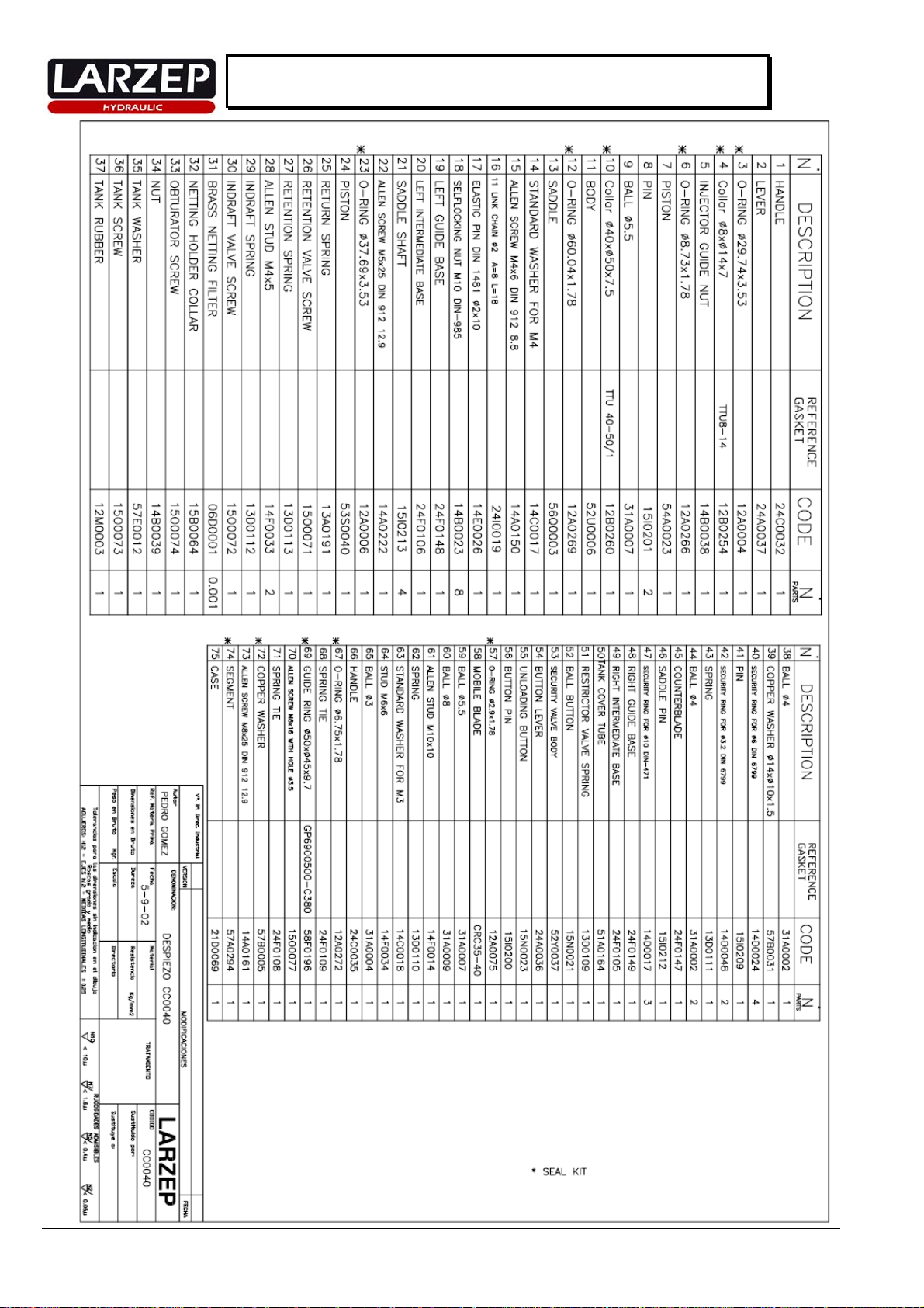
¾In the event of oil leaks, disassemble the tool and change the seals. The individual blueprint provided for each tool specifies its components and codes.
¾During this operation, check the condition of the inside of the cylinder. If scratches or snags are detected, then a more thorough repair procedure will be
required. We recommend that this be carried out by specialist personnel.
¾Check for loose nuts in the head.
¾In the event of improper functioning in the models with built-in pumps, we recommend that you send the tool to an authorised technical service for
inspection and repair.
CHANGING THE BLADE.
•CC0018, CC0118, CC0075, CC0175, CC0190 and CC01120: pump until the piston and blade move out far enough to provide access to the screw (22). Release
the screw and remove the blade. Replace the blade with a new one and attach to the piston by tightening the screw (22) once again.
•CC0040, CC0140 and CC0160: You do not need to pump the piston out, since in these models, the screw (22) can be accessed with the blade in its standby
position. Simply remove the screw (22) and replace the blade.
6. WARRANTY.
LARZEP, S.A. guarantees its products against all design and manufacturing defects for the durations of two years from the date of purchase. This guarantee does
not include the ordinary wear of both metal and non-metal parts, abuse, using the equipment beyond its rated capacity and any wear or damage incurred as a result of
using a hydraulic fluid which is not recommended by LARZEP, S.A.
Please note that if the equipment is disassembled or serviced by anyone other than an authorized service dealer or by LARZEP, S.A., this guarantee is rendered null
and void.
In the event of a warranty claim, return the equipment, to LARZEP, S.A. or the authorized dealer which sold you the hydraulic equipment, LARZEP, S.A. will
repair or replace the faulty equipment, whichever is deemed most appropriate. LARZEP, S.A. shall not be held liable for any consequential damages or losses,
which may occur as a result of faulty equipment

5
Instruction Manual
Cable and Bar Cutter “CC0040”
7. DECLARATION OF CONFORMITY.

6
Instruction Manual
Cable and Bar Cutter “CC0040”
5,5 kg

7
Instruction Manual
Cable and Bar Cutter “CC0040”
Table of contents
Other Larzep Cutter manuals

Larzep
Larzep CK0116 User manual

Larzep
Larzep CC0190 User manual

Larzep
Larzep CC0160 User manual

Larzep
Larzep CC0140 User manual

Larzep
Larzep CC0018 User manual

Larzep
Larzep CK0016 User manual

Larzep
Larzep CC0075 User manual

Larzep
Larzep CK0230 User manual

Larzep
Larzep CK0130 User manual

Larzep
Larzep CK0016 User manual