Laser Key Products 3D Pro Xtreme User manual

3D Pro
User Guide
The 3-D Pro will only operate as instructed.
Please make sure that the correct cutter and jaw combination are in place before cutting the key!!!!
It is recommended that Safety Glasses be worn at all times when operating this machine.

Table of Contents
(Clicking takes you to that page)
CHECKING YOUR NEW 3D PRO 2
COMPUTER HARDWARE REQUIREMENTS 2
THE EMERGENCY STOP BUTTON 3
SOFTWARE INSTALLATION 3
MAKING YOUR COMPUTER RECOGNIZE YOUR 3D PRO – INSTALLING DRIVERS 4
CHANGING THE CUTTER OR STYLUS 6
CHANGING TRACER 7
USING JAW 1 8
CLAMPING HIGH SECURITY KEYS THAT USE ADAPTERS “JAW 3” 10
USING JAW 2 11
CALIBRATING YOUR 3D PRO 13
SELECTING KEYS 16
SPACE AND DEPTH ADJUSTMENTS 17
EXPLAINING THE SOFTWARE, BUTTONS, TABS, BOXES AND DROP DOWN MENUS 24
USING THE EDIT SCREEN 27
USING THE SETUP SCREEN -READ FROM PC 31
TROUBLESHOOTING 32
USING AN INVERTER 33
EXAMPLE OF INVERTER CHASSIS GROUNDING 35
CHANGING THE FUSES 36
OPTIONAL ACCESSORIES 37

Page 2of 38
Checking your new 3D Pro
Please check for any damages caused during shipping, if any damage is found, please report it immediately. If damage is
not reported on the day of arrival, the customer will be responsible for any repair costs. Calibrate the machine when
your finished setting up the software as instructed on the following pages. The tracing function for duplicating keys
works only on metal; don’t try to duplicate plastic keys.
• Make sure the plastic covers on the 3D Pro are not cracked or broken.
• Check that the tracer swing arm flips up and down properly
• The machine should have no major scratches or markings
• All missing parts should be reported upon day of arrival
Contents
1 x 3-D Pro Machine
1 x Jaw 1 (High security Jaw)
1 x Jaw 2 (Standard Jaw)
1 x Jaw 3 (VW Jaw)
1 x TR 2.5 Single Ended Cutter
1 x Stylus
1 x Tip Stop
1 x USB Cable
1 x AC Power Cord
Optional Parts: Bolt-Down Kit - Laptop Mount - Tibbe Adapter - Jaw Holder
Newer 3D Pro Xtreme key machines have a hard wired motor control cable but on older machines the 9 pin serial cable
exiting the left side of the machine case should only be plugged into the 9 pin serial plug on the left side of the X table.
(see pics below) Be sure to tighten down the two small flathead attaching screws. Do not plug the 9 pin serial cable into
a computer, this will short out the control board.
Computer Hardware Requirements
• Windows XP - SP2 or higher, Windows Vista, and Windows 7 with 512Mb of RAM
• We recommend a 1,500 watt pure sine wave inverter to extend the life of your 3D Pro and laptop.
• If using an inverter to power the 3D Pro, make sure the inverter is properly grounded to the vehicles chassis otherwise
you may experience problems with the operation of the machine. Please follow your inverter manufactures installation
instructions and refer to the “Using an Inverter” page of this manual.
When cleaning key shavings from the machine, please use a brush, please do not use compressed air as doing so will
likely blow shavings into the machine and over time causing problems such as gumming up the axis’ to where the tables
could seize up or cause electrical shorts.

Page 3of 38
The Emergency Stop Button
The Emergency Stop acts as the On/Off Switch.
The “Emergency Stop Button” is situated on the
left hand side of the machine. In an emergency, hit
the button to turn off the machine. To turn the
machine on, twist the button clockwise and it will
pop out. To turn the machine off, press the button.
Note that if you simply want to cancel a key
cutting process that using the stop button on
the software is a better option.
Software Installation
Installing the Software:
1. Go to http://www.laserkeyproducts.com
2. 3D Xtreme Software on the right. Next to v15 Click ‘Purchase and Download Now’ then click ‘Add to Cart’ then click
‘Checkout’ the provide Company and other information and click ‘Submit the Information’ and in the ‘Discount Coupon’
box use the coupon code provided in the white envelope received with the machine and select ‘Use Coupon’ payment
method and click ‘Continue’ and then ‘Confirm Order’ and then ‘Download Now’.
3. The coupon Code will be in the white envelope received with the machine.
(Contact us to purchase codes and obtain the codes download password)
4. Download, extract and Run the downloaded file and follow the on screen instructions
5. Double-click your new desktop icon and the License Configuration appears.
6. Read the instructions and email us your site code and wait for a site key. Site codes are released Monday through
Friday 9am – 5pm Central Standard Time
7. If in the activation window ‘Electronic registration’ or ‘Email Registration Request’ doesn’t work then copy and paste
the site code to your webmail such as Gmail, Yahoo, or Hotmail and wait for a site key to be sent back to you, then copy
and paste the site key in the activation window and click ‘validate’
8. Once the software is activated you will likely get an error stating that the software cannot connect to the machine.
Follow the steps on the next page to configure your Device Manager.

Page 4of 38
Making your computer recognize your 3D Pro – Installing drivers
After installing the 3D Pro software, follow these steps to get the machine communicating with the computer. These
steps can also be used if you get a “Motion board not connected” Error. It’s important make sure the machine is hooked
up to the computer, powered on and configured in the device manager properly before starting the software for the
machine.
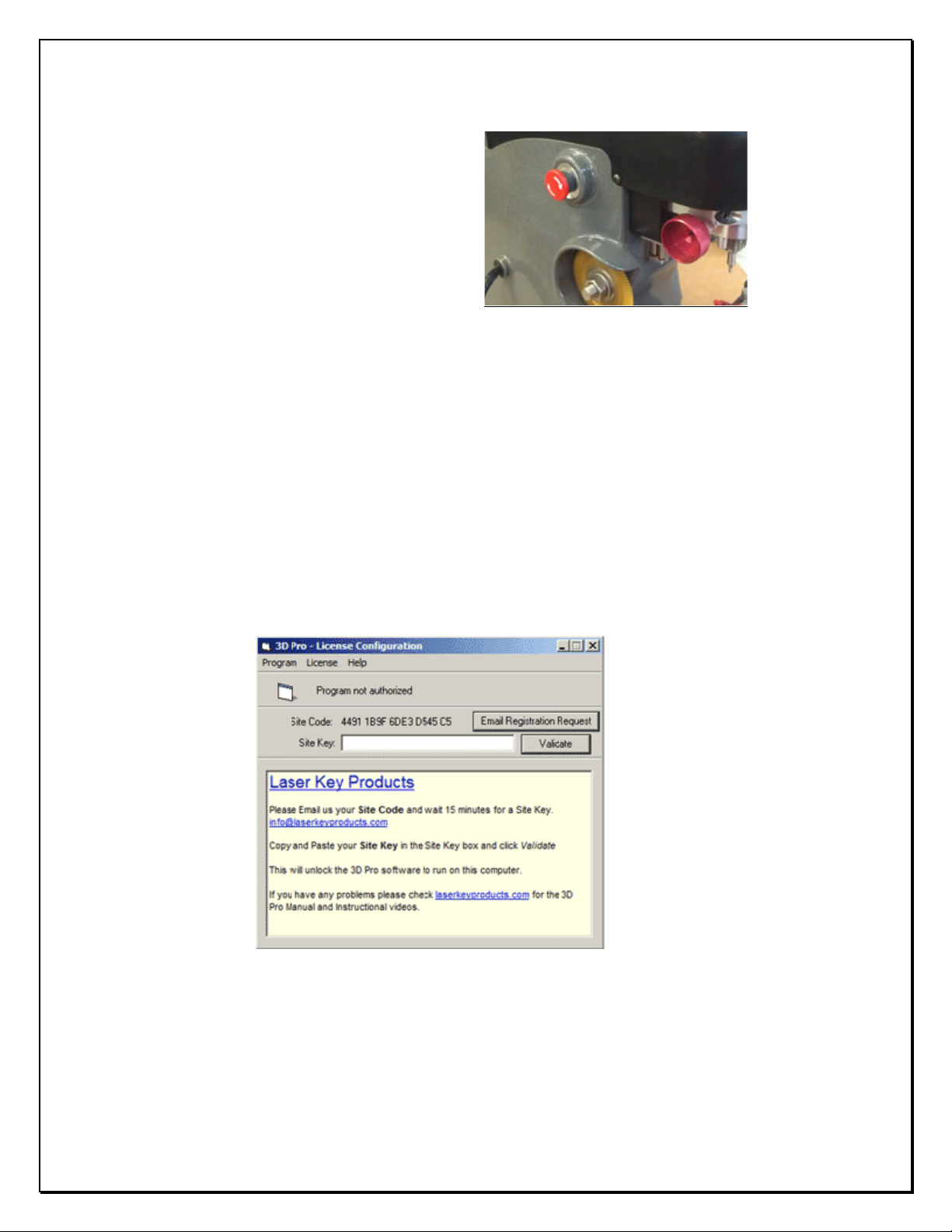
1. Connect power cord to the left side of the 3D Pro and twist out the Red Emergency Stop.
2. Connect USB cable to the right side of your 3D Pro and to any USB port on your computer.
3. Your computer should at this point install the driver automatically, if not the “Found New
Hardware Wizard” will appear. Click install from specific location and Browse to “c:\laser key products\3d pro windows drivers” and
click next and finish.
4. If step 3 didn’t work and the driver did not install then open the Device Manager from the desktop icon or click the Start menu
then Right-
click on “My Computer” or “Computer” and choose (on WinXP) “Properties” then Click “Hardware” tab and choose the “Device
Manager” button (or just Device Manager on Vista and 7) Right Click “Motion Controller” (you will notice a yellow exclamation mark
over the device) and Click “Update Driver” Choose install from specific location and Browse to “c:\ laser key products\3d pro
windows drivers” and click next then finish.
5. Once the drivers are installed correctly there will be a “COM” number assigned to it on the end of the SimpleStepSSXYZ motion
board controller.
6. Proceed once you have determined that the driver for the 3D Pro is installed correctly with no errors. Status should read “The
device driver is installed correctly”. Move onto “Finding the correct COM port”.
Finding the correct COM port
After installing the 3D Pro software, follow these steps to get the machine communicating with the computer. These
steps can also be used if you get a “Motion board not connected” Error.
1. Click the Start menu
2. Right-click on “My Computer” or “Computer” and choose “Properties”
3. Click “Hardware” tab and choose the “Device Manager” button
(or just Device Manager on Vista and 7)
4. Click the arrow next to “Ports” and the COM number should be listed on the end of the “Simple
Step Motion Controller” This is the port or COM number your computer has assigned the machine.
5. Double-click on the “SSXYZ Motion Controller” and a dialog box will appear.
6. At the top of the box, there will be a tab called “Ports Settings”, click it.
7. Click on the “Advanced” button and change the COM number to 2as this is the default
COM number set in our software.
8. Set the COM number to 2.
9. After clicking on ports, a parameter named “Baud Rate” will be shown in the “port setting” tab.
10. Click on the drop down button and a drop-down menu will appear, choose “57600” and click “Ok”
11. Close the Device Manager window, then push in the red button on the left side on the machine and unplug the
USB cable going to the computer from the machine, wait 30 seconds then twist the red button out and plug
the USB cable back into your computer and wait 30 more seconds and then start the software.
(This is what your device manager should look like after setting the COM port)

Page 5of 38
Error Connecting
If you’re experiencing connection problems and have already performed the above steps then go to ‘c:\Laser Key
Products\CommSetup’ folder. Then copy and paste the CommSetup text file into the ‘c:\Laser Key Products’ Directory.
Make sure your comm port is set to ‘2’ with a baud rate of 57600.
In the CommSetup.txt file the bottom 2 lines should read ‘2’ and ‘57600’
The number second from bottom in the CommSetup.txt file determines which COM port should be used in the device
manager.
COM Error
If you start your software and the software says “Communications Error” or “Board Not
Found” check these options:
1. Power is going to your 3D Pro from the power outlet.
2. The emergency stop button is disengaged (twisted out according to the arrows)
3. The USB cable from the 3D Pro is plugged into a USB port on your computer.
4. Multiple instances of the 3D Pro
software may be running causing a
conflict. Open Task Manager by
pressing Control Alt Delete on your
keyboard and then clicking Task
Manager.
Look for ‘3D Pro Xtreme.exe’, click
it, then click “End Process”
Then start the 3D Pro software
again.
Or
5. Follow the steps on page 4
6. Uninstall the 3D Pro software,
restart your computer and follow
the steps on pages 3 and 4.

Page 6of 38
If you still get error connecting right click the desktop icon for the 3D Pro then click the compatibility tab and set the
setting shown below.
Changing the Cutter or Stylus
“The Collet” Holds the Cutter or Stylus in the
spindle. To remove the cutter or stylus, first hold
the red knurl knob on the top of the machine
sticking up through the lid.
Then press in “spindle stop button” on the front of
the head unit. Now turn the knob on top with your
hand until you feel the spindle stop button press
all the way in. Turn the knob counter clockwise
and you will feel the collet loosen. The cutter or
stylus can now be removed.
Machines that do not have the “spindle stop
button” will have a red “knurl knob” underneath
the head unit that you will use together with the
top knurl knob to loosen the “Collet” and remove
the cutter.
When replacing the cutter or stylus, insert it into the collet and slide it up until it stops. Press the spindle stop button in
until it catches so you can tighten the collet back up on the cutter, it does not have to be extremely tight, hand tight
should be sufficient. If one of the ends of your TR62.2 double ended Jaw 2 cutter is broken, you will notice that it inserts
further into the collet than normal. This is fine but if it had just broke be sure to click on “Enter” before clicking on the
“Start” button so it will compensate for the new length. Pressing the “Enter” button causes the machine to recalculate
the cutting path.

Page 7of 38
Changing Tracer
When changing the tracer, tighten the set screw that holds the tracer tip in place in between the two dimples.
The tracing function for duplicating keys works only on metal; don’t try to duplicate plastic keys.
Changing Jaws
The black Jaw 1 is for High Security keys and the
silver Jaw 2 is for standard security keys. When
changing a jaw, look behind where the jaw is
attached, you will notice a red “T knob” Turn the
“T knob” counter clockwise to release the lock pin,
the jaw can be now be removed from the table by
sliding it off to the right.
Replacing the jaw is the same operation in reverse
order, if the jaw will not slide into place, make sure
the angle of the lock pin matches the angle of the
dovetail, and lock pin is not protruding (like the
one in the pic)

Page 8of 38
USING JAW 1
Clamping High Security Keys in
Jaw 1
Using the “Tip Stop”
When you select a High Security key, the software
will tell you which slot to place the “Tip Stop”
After you have selected the high security key, look
under the “Step 2” column on the home
screen, you will find the tip stop number next to
the box labeled “Stop”.
It will read “Tip 1”, “Tip 2”, or “Tip 3”
Now place the tip stop in the correct slot, lay the
key flat in the jaw and slide the key forward until it
touches the tip stop then tighten the jaw.
Warning: Do not forget to remove the tip stop
before tracing or cutting a key. The tracing
function for duplicating keys works only on metal;
don’t try to duplicate plastic keys.

Page 9of 38
Clamping High Security Keys in Jaw 1
Using the “Shoulder Stop”
When selecting a key
that calls for a
“Shoulder” stop, place
the key in the jaw and
slide it forward until
the shoulder of the key
is touching the front of
the jaw. No tip stop is
used for this type of
key. Tighten the red
knob to lock the key in
place.
“Jaw1” is always used
for ALL high security
(laser style keys) except VW
The Cutter used with
Jaw1 is always the
TR2.5 single ended
cutter
This is the
“Tip Stop”

Page 10 of 38
Clamping High Security Keys that use Adapters “Jaw 3”
“VW” Adaptor (Jaw 3)
When a VAG (HU66) key is selected, it requires the “VW” Adapter to be used.
Open Jaw 1 wider than you normally would to allow the adaptor to be inserted; it should slide in easily and fit on the left
side of the jaw. Slide it forward until the adapter stops and will push forward no further, see fig A.1
Now insert the key into the adapter and slide the key forward until the shoulder of the key stops on the adapter. The key
will be on the right side of this adapter once clamped in the jaw.
“B” Side
When a Mercedes 2 Track key is selected, it requires that the “B” adapter be used.
Open Jaw 1 wider than you normally would to allow the adaptor to be inserted, it should slide in the right, or moveable
side of Jaw 1 and you will notice that there is a slot on the right side that the adapter slides into, see fig A.3
The adaptor will be on the right side of the key once clamped.
Note: When using this adaptor you will also need to use the tip stop in “Tip Stop 2” (slot 2)
When a BMW HU92 2 Track key is selected it requires that the “B” adapter be used.
Open Jaw 1 wider than you normally would to allow the adaptor to be inserted; it should
slide in the slot on the “right” or moveable side of the Jaw, see fig B.1
The adapter will be on the right side of the key once clamped, see fig B.2
Note: When using this adaptor you will also need to use the “Tip Stop” in tip stop 2 (slot 2)

Page 11 of 38
USING JAW 2
When loosening the Jaw 2 clamp be careful not to unscrew the red T knob too far, doing will cause the moving Jaw 2 top
to slide out of the fixed Jaw 2 inner base and will require special instructions to reassemble.
Changing Jaw 2 Clamp
To change which jaw clamp faces the cutting
wheel all you have to do is loosen the jaw 2 and
firmly twist the jaw 2 in any direction until the
desired jaw clamp is facing the cutting wheel.
Clamping Non-High Security “Shoulder Stop” Keys in Jaw 2
When you select a standard
security key from the
menu, the software will
tell you which “Stop” to
use, “Shoulder” or “Tip”
This is an example of a
Shoulder Stop key.
Slide the key forward until
it stops on the shoulder of
the key. Tighten the red
knob on top until the key is
clamped firmly.

Page 12 of 38
Clamping Non-High Security “Tip Stop” Keys in Jaw 2
This is an example of a
Tip Stop key.
Insert the key into the
jaw and raise the “Tip
Stop” slide the key
forward until it touches
on the stop.
Remember to fold the “Shoulder” or “Tip” Stop back down before you start to “Trace” or “Cut” a key
Be sure that all keys are inserted completely into the back
(bottom) of the Jaw unless otherwise specified in the text
box on bottom of the home screen.
The message will appear once the key is selected, if there
are any notes like “clamp key on milling” it will appear
here.
Circled in RED is the milling of this Y157 Key.
It is the thinest part of the key along the edge.

Page 13 of 38
Sometimes, depending on the blank
used, the key will try to twist out of
the jaw or otherwise not clamp
properly. A shim can be used to hold
the key tight as illustrated. In the
example to the right we are using a
hex wrench to shim the key.
Cut Types
Slotted Cuts are not available at this time.
Laser Cut
Plunge Cut
When tracing or cutting the second side of a double sided key, if there is no 1 depth toward the tip of the key it will not
automatically align in the jaw. To keep the key correctly aligned in the jaw, you must align the key by eye.
The best way to do this is compare the milling marks on the key to the straight edge of the jaw.
Calibrating your 3D Pro
If you get “Obstruction Detected” errors you may need to calibrate, make sure you are calibrating with the stylus and
not the cutter.
Calibrating Cutter for Jaw 1
1. Clean any shavings or debris from jaw (Any metal shavings,
dirt or grease that the stylus touches will take an incorrect
reading). And open Jaw 1 all the way!
2. Put the Stylus in the collet. The Stylus must be used to
calibrate.
Do not use cutters to calibrate or else your keys will cut wrong.
This is the Stylus.
3. Make sure the tracer arm is up, if the tracer arm is down, you will receive an error message.

Page 14 of 38
4. On the main screen, click on the “Operations”
menu and choose “Calibrate Machine”
5. When the window appears asking to “Select Jaw”
insert the correct jaw number in the window, 1
(1, 2, or 3 depending on which jaw you want to
calibrate) as we are calibrating Jaw “1” we would
enter “1” and click “OK”
6. The stylus will touch the jaw in three places. After the procedure is complete it will say
“Update in Progress Please Wait” give it a moment and don’t click anything or it can possibly freeze the
software and you will have to restart it.
Calibrating Tracer for Jaw 1
1. Always have a “Cutter” or “Stylus” installed
while calibrating the Tracer, do not leave the collet
empty or it will get in the way of the Tracer.
2. Flip the tracer arm down with the “red knurl
knob” on the left side of the head.
3. On the main screen, click on the “Operations”
menu and choose “Calibrate Tracer”
4. When the window appears asking to “Select
Jaw” insert the correct jaw number in the window,
(1, 2, or 3 depending on which jaw you want to
calibrate) as we are calibrating Jaw “1” we would
enter “1” and click “OK”
5. The tracer tip will touch the jaw in three places.
After the procedure is complete it will read,
“Update in Progress Please Wait” give it a moment
and don’t click anything or it can possibly freeze
the software and you will have to restart it.
Calibrating Cutter for Jaw 2
1. Clean any shavings or debris from jaw (Any
metal shavings, dirt or grease that the cutter
touches will take an incorrect reading)
2. Close the Jaw 2 so that it is completely shut with
the ‘A’ side facing the cutter wheel
3. Flip the Shoulder stop up and the Tip stop down
as pictured.
4. On the main screen, click on the “Operations”
menu and choose “Calibrate Cutter”

Page 15 of 38
5. When the window appears asking to “Select
Jaw” insert the correct jaw number in the window,
(1, 2, or 3 depending on which jaw you want to
calibrate) as we are calibrating Jaw “2” we would
enter “2” and click “OK”
6. The cutter wheel touches the front of the A side
of the Jaw 2 and then moves to the left and
touches the shoulder stop then goes home.
After the procedure is complete it will read
“Update in Progress Please Wait” give it a moment
and don’t click anything or it can possibly freeze
the software and you will have to restart it.
Jaw 2 may need minor adjustments to space or depth after calibrating to be correct.
Refer to the section “Checking and Adjusting the “Tracer” for instructions.
There is no tracing for J2 at this time.
Calibrating Cutter for Jaw 3
1. Clean any shavings or debris from jaw
(Any metal shavings, dirt or grease that
the stylus touches will take an incorrect
reading). And open Jaw all the way!
2. Put the Stylus in the collet. The Stylus
must be used to calibrate.
Do not use cutters to calibrate or else
your keys will cut wrong.
3. Make sure the tracer arm is up, if the
tracer arm is down, you will receive an
error message.
4. On the main screen, click on the
“Operations” menu and choose
“Calibrate Machine”
5. When the window appears asking to
“Select Jaw” insert the correct jaw
number in the window, 1 (1, 2, or 3
depending on which jaw you want to
calibrate) as we are calibrating Jaw “3”
we would enter “3” and click “OK”
6. The stylus will touch the jaw in three
places. After the procedure is complete
it will say “Update in Progress Please
Wait” give it a moment and don’t click
anything or it can possibly freeze the
software and you will have to restart it.

Page 16 of 38
Calibrating Tracer for Jaw 3
1. Never have a “Cutter” or “Stylus”
installed while calibrating the Tracer,
leave the collet empty or it will get in the
way of the Tracer and cause an error.
2. Flip the tracer arm down with the “red
knurl knob” on the left side of the head.
3. On the main screen, click on the
“Operations” menu and choose
“Calibrate Tracer”
4. When the window appears asking to
“Select Jaw” insert the correct jaw
number in the window, (1, 2, or 3
depending on which jaw you want to
calibrate) as we are calibrating Jaw “3”
we would enter “3” and click “OK”
5. The tracer tip will touch the jaw in
three places. After the procedure is
complete it will read, “Update in
Progress Please Wait” give it a moment
and don’t click anything or it can
possibly freeze the software and you will
have to restart it.
Selecting keys
There are three ways to select keys in the 3D Pro
software, if you can’t find a key one way then try
another. If you try to select a key from the year
make and model selector only to find the year you
have is not listed then try the closest year or make
of vehicle or select the key from one of the other
two key selection tabs.

Page 17 of 38
The Type/Manufacturer tab allows you to select a
key by blank name. After clicking this tab select a
manufacturer
The Search tab allows for selecting keys by DSD
number, blank name, year make and model name
and more.
SPACE AND DEPTH ADJUSTMENTS
The following pages will show you how to check and set your machine to cut and trace perfectly.
Explaining the X, Y, Z Axis for Jaw 1 and Jaw 3
1. Jaw 1 uses three axes which are X, Y, and Z
2. The X axis is the movement from left and right and controls the depth.
3. The Y axis is the movement from front to back and controls the spacing.
4. The Z axis is the movement up and down and controls the height at which the cutter is lowered.
Explaining the X, Y, Z Axis for Jaw 2
1. Jaw 2 uses two axes which are X and Y.
2. The X axis is the movement from left and right and controls the spacing.
3. The Y axis is the movement from front to back and controls the depth.
All adjustments are in .001” (one thousandths of an inch)
The “Space” or “Depth” on either the “Tracer” or the “Cutter” can be adjusted by a maximum of “.020” (20 thousands)
either way (+ or -) plus or minus. You will need to know how to measure keys with calipers.

Page 18 of 38
Adjustments are made by going to “Operations > Space and Depth Adjustment” and the typing 1, 2 or 3 for Jaws 1, 2 and
3 and clicking OK.
Adjusting Space and Depth on Jaw 1 and Jaw 3
High security keys that are cut and traced on Jaws 1 and 3 uses a profile that can be shifted along the space and depth.
We will use a High Security Honda key as an example of how to adjust Jaw 1.
In the 3D Pro software with this Honda key
selected go to: ‘File > Edit’ and at the bottom is
the Depth and Space Data (DSD)
Below is a visual representation of the DSD.

Page 19 of 38
To measure the
spacing on a tip stop
key like the high
security Honda key set
a caliper to the space
that you want to
measure using the
space data on the edit
page and the measure
from the tip toward
the bow. For a
shoulder stop key,
measure from
shoulder to tip.
To measure a depth on
a high security Honda
key, find the space for
the depth you want to
measure and measure
from the edge of the key
to the edge of the cut.
Compare the reading
against the Cut Depth
info on the edit page.
Now trace either a blank or OEM cut high security Honda key. It’s best not to use an
aftermarket key because it may not be cut to spec. In this example we are tracing an
OEM cut key.
At the bottom right hand corner of your 3D Pro software is a text box, and at the
bottom of this box are the readings for the trace, one line per cut. The readings show
the space, cut and tracer measurement. The readings are shown in the order in which
they have been traced.
A blank will read all zeros measuring 352 all the way down the key.
An OEM key should always read ones in both 6th spaces measuring 311.
The 6th spaces will show in the middle of the readings list and we see in the example
that the key profile is off to the left by 3 thousandths of an inch. The trace reading
shows that the 6th space on side A measured to 308 thousandths of an inch when it is
supposed to be 311 thousandths of an inch. This in turn causes the 6th space on side B
to be off as well. To correct this we will make a space and depth adjustment to move
the cut profile to the right by 3 thousandths of an inch. This will make the 6th space on
side A measure 311 and the 6th space on side B measure 310.
[Trace Reading Example]
(1,3);283
(2,5);253
(3,5);253
(4,4);268
(5,5);253
(6,1);308
(6,1);313
(5,5);256
(4,1);312
(3,5);256
(2,6);242
(1,4);269
To make this adjustment go to “Operations > Space and Depth Adjustment” type “1” and press “OK”
Other manuals for 3D Pro Xtreme
1
Table of contents