LaserLine GL3000PMC-E User manual

1810 SE First Street, Suite H, Redmond, OR 97756
Phone 541 548 0882 • Fax 541 548 0892 • Email laserline@laserline.net
Website www.LaserLineMfg.com
LaserLine Manufacturing, Inc.
GL3000PMC-E
OWNER’S MANUAL
Wing Plow & Guidance Alignment Laser
US Patent No. 7,966,753
EU / IEC
REV. 3.27.18

©2009 LaserLine Manufacturing, Inc.
GL3000PMC-E
OWNER’S MANUAL
Wing Plow & Guidance Alignment Laser
table of contents
Winter Operation Snow Plow Guide — System Overview: What It Does & How It Works 2
Components & Controls: Control Box 3
Components & Controls: GL3000PMC-E Laser 4
Winter Operation / Snow Plows — Maintenance, Service & Installation Suggestions 5
Installation & Aiming the Laser for Snow Plows 6
Snow Plow Operation 7
Operation: Straight, Outside Curve & Inside Curve 8
GL3000PMC-E Specifications 9
Laser Emission Information 9
GL3000PMC-E Warranty 9
10
Laser Safety 11
GL3000PMC-E Product Labeling 11
Controls & Emissions 12
1
Caution

2
WINTER OPERATION SNOW PLOW GUIDE
SYSTEM OVERVIEW: WHAT IT DOES & HOW IT WORKS
THE SYSTEM
The GL3000PMC-E Guidance Laser uses an “ultra-
bright” green laser to establish wing plow trailing edge
location before you get there.
The laser spot impacts on the road/snow surface ahead
of the truck and shows the driver where the wing plow
trailing edge will be. The laser reference spot is on the
road and in the driver’s normal field of view.
The GL3000PMC-E is electronically designed for cold
weather operation. This laser is coupled to a special
heat source for the exit window to reduce or eliminate
ice build-up on the front of the laser output lens. The
GL3000PMC-E also has a unique pneumatic snow re-
moval system incorporated with the laser housing that
automatically fires a blast of air at the front of the laser
lens every 5 seconds. This removes snow build-up from
the laser output lens.
The laser housing is weatherproof, and hermetically
sealed and dry nitrogen charged for operation in virtu-
ally any weather condition.
THE PRODUCT
The GL3000PMC-E is a versatile all weather product
that can also be used for guiding highway paint stripers,
asphalt distributors, pavement profilers, or virtually any
other vehicle or equipment requiring line control. Use it
in the winter and summer for all your guidance needs.
Main Housing: Weatherproof, containing optic plate
mounting platform, micro processor electronics, laser,
laser mounting assembly, laser driver board, automatic
cooling and heating system, front window is automati-
cally heated to reduce or eliminate icing.
Pneumatic Air Blast Module: Removes snow build up
from laser exit window with automatic air blast every
5 seconds.
Control Panel In Cab: Allows the operator to turn the
laser on and off as well as the deicing and automatic air
blast functions.
20 Feet (6.09 Meters) of Interconnect Cable: With wa-
terproof mil spec in-line connector mounted between
the laser main housing and the control panel mounted
in the cab.
5 Feet (1.52 Meters) of 12V DC Cable: Running from
control box for connection to vehicle’s 12V DC power.
20 Feet (6.09 Meters) of 1/4-Inch Pneumatic Hose Line:
Complete with connectors for tying into vehicle’s sec-
ondary air source.
THE ADVANTAGES
•Cuts damage caused by plow strikes by 80 to 100%.
• Less strain on the driver.
• Reduces equipment down time.
• It’s much safer.
• It will save you money.
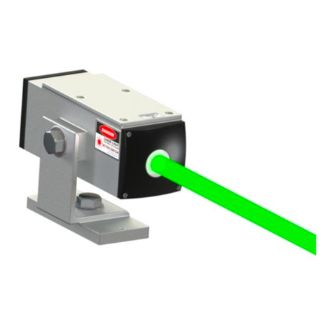
GL3000PMC-E Guidance Laser Laser spot showing future path of trailing edge GL3000PMC-E laser shown
US Patent No. 7,966,753
The systems work directly off the 12 volt side of the
truck, and will operate from
tive or negative ground.
12 to 24
DC with posi-

3
CONTROL BOX
1Key Switch
Controls power access.
Requires key to operate laser.
2Main Power Switch
3Laser Mode Switch
with Redundant Dual LED Emission Indicator.
1st depression = Laser on steady
2nd depression = Laser on blinking
3rd depression = Laser off
4Deicer Switch
with status light
Leave on during freezing temperatures.
5Remote Interlock Interface Port (optional)
Provides connection source for external laser shut
off switch. Shown with Shorting Bar installed.
6Shorting Bar - Remote Interlock Port
Remove if wiring the system for remote
laser shut off.
7
White wire = +12
Black wire = -12
The GL3000PMC-E has reverse voltage protection.
8Laser Control Cable
Connects control box to laser head.
9Plow Position Sensor Wire (optional)
Connects to the hot wire on “power up gravity
down” wing plow control systems.
The laser will turn on when the wing plow is down
and off when the wing plow is up.
Acts as a further indicator to the driver of the
plow position (along with visually checking
the plow position and the plow status light
on the plow control).
COMPONENTS & CONTROLS:
CONTROL BOX & POWER SUPPLY
1
10
5
3
4
2
8
7
9
6
Redundant Dual LED
Laser Emission Indicator
10
Protection 3 amp Fuse (3amp MAX)
Turn on power, leave on entire shift.
Power Cable to Vehicle 12 or 24 VDC
White wire positive.
(15 feet)
/ 24 Vdc
/ 24 Gnd

4
GL3000PMC-E LASER
11 Vertical Aiming
Loosen to aim; retighten.
12 Horizontal Aiming
Loosen to aim, retighten.
13 Mounting Holes (2)
Two holes provided to mount
laser to stable surface.
14 Heated Laser Exit Window
Automatically heats entire front of laser
to eliminate snow and ice.
15 Pneumatic Snow Removal Module
Houses the pneumatic valve that sends an air
blast automatically every 5 seconds to keep the
Exit Window clear of snow and ice.
16 Air Blast Nozzle
Directs air blast across the face of the
Exit Window.
17 Redundant Dual LED Emissions Indicator
18 Input Coupling from Air Supply
Accepts 1/4 inch pneumatic hose from
filtered supply line.
19 Mil Spec Connector
Connects control box to laser.
20 Purge Valve Set at Factory
Do not tamper with. Will void warranty.
COMPONENTS & CONTROLS: GL3000PMC-E LASER
WARNING!
Laser is filled with dry nitrogen to prevent
moisture. Do not open or tamper with purge
valve, front, rear or bottom covers. No user
or non certified persons shall access interior
of laser! Removal of covers will violate IEC
Regulations and Factory Warranty.
15
11
16
12
13
17
14
18
19
20

5
MAINTENANCE
The only maintenance that may be required is:
1. Periodically clean the Exit Window of the GL3000PMC-E.
Do this with a soft cloth. Do not use Kleenex or paper
towels. Be careful not to scratch the glass.
2. Periodically blow the pneumatic lines to clear
moisture from the system.
Note: Always turn off power to the laser when cleaning
the Exit Window.
SERVICE
No service is required and no service is to be performed
by the Customer. Only LaserLine Mfg., is authorized to
perform laser service. Any opening, tampering with, or
modifying the GL3000PMC-E Laser Housing by anyone
other than LaserLine Mfg., Inc. will void the warranty.
Under no circumstances, attempt to open or disassemble
the main Laser Housing.
The pneumatic air blast module may be opened for ser-
vice or valve replacement.
See page 3 item 10 for location.
INSTALLATION SUGGESTIONS
1. The laser must be mounted to a stable surface. If the
laser base is vibrating (too flimsy a mount) on the vehicle,
the vibration is magnified at the laser spot and can make
it difficult to see. Stability of the laser mount is very
important.
2. Do not mount the laser inside the cab and shoot the
laser beam through the windshield without the use of a
boot to prevent back scatter. Call the factory for details.
3. Do not mount the GL3000PMC-E laser unit in a location
that allows the laser beam to be directed to hit any mirror
like reflective surfaces on the vehicle such as mirrors.
WINTER OPERATION / SNOW PLOWS
MAINTENANCE, SERVICE & INSTALLATION SUGGESTIONS

6
INSTALLATION & AIMING THE LASER FOR SNOW PLOWS
INSTALLATION
Mount the GL3000PMC-E Laser on the far right side (Fig. 1)
of the vehicle (passenger side) on top of the cab, on the
underside of the headache rack (Do NOT use the headache
rack if it rides with the dump function, only if it is perma-
nently attached to the frame), or to the rear view mirror
mount if stable. If the plow trailing edge is on the driver’s
side, mount the laser on the far left.
If activating Plow Position Sensor see item 6 on page 3.
Run pneumatic line to secondary dry air source; i.e., under
driver’s seat. A 40 micron air line filter on the pneumatic
supply line to the laser is recommended.
AIMING THE LASER
With the Wing Plow in the down position (Fig. 2), measure
the distance from the outside of the front and rear outside
tire line to the outer edge of the Wing Plow trailing edge.
Note: Front Wheels must be straight.
Extend the wheel line out about 60 feet (18 meters) in
front of the vehicle (Fig. 3). Make sure the line is perfectly
straight and in line with the outer wheel line. This should
be done on a flat surface or continuous slope running fore
and aft of the truck. Measure along the tire line out the
distance in front of the truck that you want the laser spot
to be (i.e., 50 feet or 15.24 meters). From that point, mea-
sure over to the right the width of the Wing Plow (i.e., 6 feet
or 1.828 meters) plus about 6 to 12 inches (15 to 30 cm) for
a cushion. Set the laser spot at that point and lock it down
securely using the Adjustment Bolts on the Laser Housing.
The distance in front of the truck that you set the laser
spot at depends on your own typical driving speed. This
distance could be anywhere from 20 feet to 60 feet (6 to
18 meters) or more (Fig. 4).
Mirror Mount
Underside of
Headache Rack
(Only if rack is
attached to frame.
Do not attach if rack
rides with dump
function.)
Or
Top of Cab
FIG. 1
FIG. 2
FIG. 3
6’
6’60’
50’
40’
30’
20’
10’
(18.28 m)
(15.24 m)
(12.19 m)
(9.14 m)
(6.09 m)
(3.04 m)
Driving Speed Approximate laser spot
distance from truck
35
25
15
56
40
24
40-60
30-40
20-30
12-18
9-12
6-9
Mph Kph Feet Meters
FIG. 4
(1.828m)
Run power to the 12 or 24V side of the electrical system,
either tied to or separate from the ignition system.
Note:
Attach to minimum 10 amp circuit using minimum of 16
gauge wire.

7
1A) Turn on the Main Power Switch 15-20 minutes prior
to plowing. This puts the laser module in “preheat”
to get the laser up to operating temperature. The
laser status light (green light above laser mode
switch) will slow-blink until the system is warmed
up, and then on steady when the laser is activated.
B) Turn on the Deicer Switch right after you turn on
the main power switch. Leave this switch on for the
entire shift. This switch activates both the anti-ice
heater on the front of the laser module as well as
the pneumatic air blast module for snow removal
from the front lens.
2 Do a visual check of the laser housing. If the front of
the unit is packed with snow and ice, wipe it off. It is
not unlike your windshield: if it’s covered with snow
and ice, you cannot see through it. The same is true
for the laser: if the output lens is not clear, the laser
will not go through (see through) it.
3 The GL3000PMC-E laser spot puts your trailing edge
location ahead of you and shows you what you will
hit if you do not take action. It virtually eliminates
continually looking in the rearview mirror for trailing
edge location.
• The mirror shows what you just hit.
• The laser shows you what you will hit!
It cuts down on strikes and damage dramatically
because it gives you a heads-up about where your plow
trailing edge will be ahead of time.
4 The laser is effective at letting you know your plow
location and whether or not you will clear an object
on long shallow curves and straight runs. When go-
ing around corners, it will not work for you, but once
around the corner it sets you up for your run relative to
guard rail, bridge curb lip, abutments, mailboxes, etc.
5 The laser spot reference ahead of you is more visible or
less visible depending on conditions. If it is bright and
sunny, and you’re plowing slush, you probably will not
see the laser spot, as water sucks out the color. Gen-
erally speaking, the worse the visibility and driving
conditions are, the better it works for you, and that, of
course, is when you need it the most.
6 Laser Enhancement Glasses (part number 3000-0435)
block out glare and increase laser spot visibility for the
driver in daylight operations.
SNOW PLOW OPERATION
DRIVING CONDITIONS USING THE LASER:
The worse it gets,
the better it works!

8
Outside Curve
800 Ft Radius
Inside Curve
Straight Road
STRAIGHT ROAD
As indicated
Outside Curve
800 Ft Radius
Inside Curve
Straight Road
OUTSIDE CURVE
More room than indicated
INSIDE CURVE
Less room than indicated

9
Laser 532nm Class 3B
Power Volt DC Positive or Negative Ground
Power Draw 4.00 Amps (Maximum Operating)
0.03 Amps (Sleep Mode)
Recommended Ambient
Operating Temperature +36ºF to +120ºF / +2.2ºC to +48.8ºC
Storage Temperature -40ºF to +150ºF / -40ºC to +65ºC
Laser Housing and Mount
Height 15.615 cm (6-3/8 Inches)
Length 18.655 cm (7-7/8 Inches)
Width 10.79cm (4-1/4 Inches)
Cable Length From Laser Housing to Control Box 6.1 m (20 Ft)
4.6 m (15 Ft)
Shipping Weight 11.34 kg (25 Lbs)
GL3000PMC-E SPECIFICATIONS
FACTORY SERVICE CENTER
LaserLine MFG., INC.
1810 S.E. First Street, Suite H,
Redmond, OR 97756, USA
Phone: 1-541-548-0882
Fax: 1-541-548-0892
Email: Laserline@laserline.net
FACTORY SERVICE: New Product Warranty service policy for new products stated above.
SERVICE WARRANTY: 1 year on replacement Parts, 90 days on Labor.
FOR ALL WARRANTY: Call Order Processing for RMA # at 1-541-548-0882. The Unit will be repaired
and returned by prepaid freight.
NON-WARRANTY
Send to: LaserLine MFG., INC. at above address.
GL3000PMC-E WARRANTY
This product is guaranteed against defects in materials and workmanship with parts and labor, under
normal working conditions from one year from the date of purchase, except as noted herein.
LaserLine Mfg., Inc. liability under this warranty is limited to repairing or replacing any product returned
to an authorized service center for that purpose. Any evidence of attempts to repair this unit by other
than factory authorized personnel automatically voids the warranty.
Warning! Under no circumstances, attempt to open or disassemble Laser Housing.
LASER EMISSION INFORMATION
Laser Source Nd: YAG
Wavelength 532nm
Full Aperture Output Power <40mW (35mW Typical)
7mm Aperture Power at 20cm Distance <5mW
Full Aperture Beam Diameter <25mm
Beam Diameter 1/E2 14mm
Divergence <0.1mrad
Beam Mode (Profile) TEM00
Emission CW or 2Hz
Laser Class EU 3B
Laser Class USA IIIa
US Patent No. 7,966,753
12 to 24
12 /24
Volt Power Cable Length from Control Box

10
Email: laserline@laserline.net
Web: Laserlinemfg.com otherwise, set it up well below.
CAUTION!
Do not expose this Laser to:
• High pressure washing
• Car wash
When cleaning front window, use window cleaner
with paper towel or clean cloth. No abrasives.
Store in clean, dry environment when not in use.
WARNING!
Do not open or tamper with the purge
valve, front, rear or top covers. Laser is
filled with dry nitrogen to prevent moisture
from damaging internal electronics and
optics. No user access to interior
components! Removal of covers will violate
IEC/OSHA Regulations and Factory
Warranty.
WARNING!
Do not open or tamper with the purge
valve, front, rear or top covers. Laser is
filled with dry nitrogen to prevent moisture
from damaging internal electronics and
optics. No user access to interior
components! Removal of covers will violate
IEC/OSHA Regulations and Factory
Warranty.

11
LASER SAFETY
The GL3000 Series Laser is a Class 3B Laser Product.
Class 3B Lasers are used every day in construction and
alignment applications. With every use, eye safety is a
consideration.
The Operators of the laser are effectively the “Safety
Persons”, and should think of themselves as the person
responsible for preventing accidents and unwanted
exposure.
The operation of Class 3B lasers are generally to be
overseen by a Laser Safety Officer (LSO) in your facility
or organization. For further data regarding suggested
or required operating parameters consult the IEC 60825
family of standards and/or your national and local gov-
ernment safety organization.
Viewing or looking at the laser spot impacted on the
road or highway is normal operating procedure for the
GL3000 and is how the product is used for guidance ap-
plications. There is no danger or hazard to the Operator
or Driver using the laser in this manner.
SAFETY CONSIDERATIONS:
• When installing the GL3000 Laser, do not mount the
laser inside the cab and shoot the laser beam through
the windshield. This is an unsafe practice as the laser
beam can reflect back off the windshield into the Op-
erator’s eyes (backscatter).
• Do not mount the GL3000 Laser in a location that
allows the laser beam to be directed to hit any shiny
or reflective surface on the vehicle, such as chrome,
side mounted rear view mirrors, or glass surfaces.
• Class 3B Lasers are bright lights that can or may be
aimed. Be aware of people and your surroundings.
• Therefore, think of the laser as the sun, something
you do not stare back into. Do not look at the laser
through optical devices, or look at it reflected off of
shiny surfaces such as chrome, glass or mirrors.
• Viewing the laser beam or a reflection of the beam
with optics, such as binoculars or cameras can be
hazardous because they can gather or concentrate
the laser right to the eye.
• Turn laser off in the event of potential exposures: i.e.,
stopped at a crosswalk in the vicinity of pedestrian traf-
fic. Watch for the reflection off of bumpers, windows, etc.
• CAUTION!Useofcontrolsoradjustmentsorper-
formance of procedures other that those specified
herein may result in hazardous radiation exposure.
• Do not open laser housing, no user serviceable parts
inside. Service to be performed ONLY by manufacturer.
• Do not mount the GL3000PMC-E laser unit in a location
that allows the laser beam to be directed to hit any mir-
ror like surfaces on the vehicle such as mirrors.
GL3000PMC-E PRODUCT LABELING
Note: Maintain these labels in there proper locations.
Aperture Label
Hazard Label
Explanatory Label
Identification Label
LASER SAFETY
GL3000PMC-E PRODUCT LABELING
Note: Maintain these Labels in their proper Locations.
Aperture Label
Hazard Label
Explanatory Label
Identification Label
LASER SAFETY
GL3000PMC-E PRODUCT LABELING
Note: Maintain these Labels in their proper Locations.
Explanatory Label
Identification Label
Aperture Label
Hazard Label

12
CONTROLS & EMISSIONS
WARNING!
Laser is filled with dry nitrogen to prevent moisture. Do
not open or tamper with purge valve, front, rear or bottom
covers. No user or non certified persons shall access interior
of laser! Removal of covers will violate IEC Regulations and
Factory Warranty.
CONTROL PANEL
1Key Switch
2Main Power Switch
3Laser Mode Switch
Dual LED Emission Indicator.
1st depression = Laser on steady
2nd depression = Laser on blinking
3rd depression = Laser off
4Deicer Switch
with status light
5Remote Interlock Interface Port
Shown with Shorting Bar.
6
7Laser Control Cable
8Plow Position Sensor Wire
The laser will turn on when the wing plow
is down and off when the wing plow is up.
9 Vertical Aiming
10 Horizontal Aiming
11 Redundant Dual LED Emissions
Indicator
Laser and Control Box
12 Laser Control Cable Receptacle
LASER SPECIFICATIONS
Laser Source YAG
Wavelength 532nm
7mm Aperture Power at 20cm Distance < 5mW
Diameter 25mm
Divergence < 0.1mrad
Emission CW or 2Hz
LaserClassEU 3B
LaserClassUSA IIIa
Laser Aperture
1
Redundant Dual LED
Laser Emission Indicator
6
8
7
3
5
2
4
11
10
9
12
Turn on power, leave on entire shift.
Power Cable to Vehicle 12 or 24 VDC
White wire positive.
(15 feet)
Table of contents
Other LaserLine Measuring Instrument manuals

LaserLine
LaserLine QUAD 1000HDD User manual

LaserLine
LaserLine DigiLevel Compact User manual

LaserLine
LaserLine GL3000PMC User manual

LaserLine
LaserLine WoodTester User manual

LaserLine
LaserLine MoistureFinder Compact User manual

LaserLine
LaserLine SuperCross-Laser 2P User manual

LaserLine
LaserLine GL3000PM User manual

LaserLine
LaserLine PrecisionPlane-Laser 3D Pro User manual

LaserLine
LaserLine GL3000P-E User manual

LaserLine
LaserLine 310 User manual