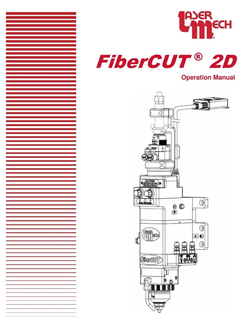
LaserMech FiberCUT HR User manual

FiberCUT
®
HR
Operation Manual

PLMNL0252 REV. B Effective Date: 10/16/17 iFiberCUT®HR Operation Manual
WARNING
WORKING AROUND HIGH-POWERED LASERS
CAN BE DANGEROUS
Laser Mechanisms, Inc.’s cutting heads must be
operated with the cutting head interlock switch
connected. The switch must be CLOSED when the
head is properly attached. In the event of a crash
and the cutting head becoming dislodged from its
normal operating position, the switch must be
OPEN. This interlock switch must be connected
in a circuit in such a way that it will immediately
turn off the laser and stop all machine motion.
Check the wiring diagrams for your system.
Serious personal injury and/or equipment
damage can occur if the head becomes
dislodged and:
The head interlock is not connected
properly.
Any interlock in the Laser Mechanisms’
product or laser system is defeated.
Laser Mechanisms, Inc. assumes no responsibility
or liability for interlock switches or circuits and all
interlocks are the sole responsibility of the purchaser
of this head.
It is the responsibility of the integrator or end user to
install, connect and activate all interlocks in
compliance with the applicable ANSI, CEN, DIN, etc.
standard.
All wiring should be done by personnel
knowledgeable in electrical wiring and in accordance
with the national and local electrical codes.
DISCLAIMER
The information in this manual is subject to change
without notice.
Laser Mechanisms, Inc. makes no warranty of any
kind with regard to the material in this manual,
including but not limited to, the warranties or
merchantability and fitness for a particular purpose.
Laser Mechanisms, Inc. shall not be liable for errors
contained herein or for incidental or consequential
damages in connection with furnishing, performance
or use of this product.
Laser Mech®is a registered trademark of Laser
Mechanisms, Inc.
Corporate names and trademarks stated herein are
the property of their respective companies.
COPYRIGHT
©2017 Laser Mechanisms, Inc. All rights reserved.
No part of this publication may be reproduced in any
form, or by any means without the prior written
permission of Laser Mechanisms, Inc.
PRODUCT WARRANTY
Laser Mechanisms, Inc. warrants this product
against defects in material and workmanship for a
period of one year from the date of shipment from
Laser Mechanisms Inc. or an authorized distributor.
During the warranty period, Laser Mechanisms, Inc.
will at its option, repair or replace products that
prove to be defective.
For all products returned to Laser Mechanisms, Inc.
for warranty service the customer must:
Call Laser Mechanisms, Inc. for a Return
Material Authorization (RMA) number.
Properly pack the product with the RMA number
on the outside of the package. Include in the
package, all cables, and all accessories shipped
with the product along with a description of the
problem.
Prepay shipping charges to Laser Mechanisms,
Inc.
Insure the shipment in case of loss or damage.
Laser Mechanisms, Inc. will not accept any
liability in case of damage or loss.
Laser Mechanisms, Inc. will pay the shipping
charges, duties and taxes for the products returned
to Laser Mechanisms, Inc. from outside the United
States.
The foregoing warranty will not apply if damage is
incurred resulting from improper or inadequate
maintenance by the customer, unauthorized
modifications or misuse, operation of the product
outside its specifications, interlocks not connected
properly, improper site preparation, parts or
assemblies not supplied by Laser Mechanisms, Inc.
or unauthorized repair by non-Laser Mechanisms,
Inc. authorized personnel.
For complete warranty information visit our web site
at www.lasermech.com.

PLMNL0252 REV. B Effective Date: 10/16/17 ii FiberCUT®HR Operation Manual
INITIAL INSPECTION
Inspect all shipping containers for damage as soon
as the device arrives. It is your responsibility, the
recipient, to notify the freight company of any
damage. The freight company will require you to
provide the container that any goods were shipped
in, all shipping documentation and a list of all
damages. Photographs of the damage are helpful in
settling a freight claim.
Do not return damaged goods to the factory
without a Return Material Authorization Number
(RMA number).
Although it is Laser Mechanisms, Inc.’s intent to
insure you are up and running as soon as possible,
damage incurred during shipment must be settled
with the freight company before arranging for repairs
or replacement. No return shipments will be
accepted without an RMA number clearly printed on
the outside of all shipping containers. Failure to
follow this procedure could void any warranty
coverage on your head. Call your sales engineer at
Laser Mechanisms, Inc. for a RMA number.
Carefully remove the device from its shipping
container and all packing material to avoid damage.
Save all packaging material, including the sealed,
padded pelican case, in the event the head requires
shipping or storage.
Check all items received against the packing list
to verify that all the items were received.
Please note the product you receive may differ
slightly from the illustrations in this manual.
While the drawings may differ, the basic
procedures described within remain the same.
TERMS USED IN THIS MANUAL
WARNING: The user could be injured
if the warning is not followed.
CAUTION: The device or system
could be damaged if the CAUTION is
not followed.
NOTE: Clarification of a step or steps.
SAFETY
WARNINGS: Follow all warnings in this
manual.
SAFETY GLASSES: Everyone in the area
where the laser is being used must wear laser
safety glasses designed for the laser being
used.
SECONDARY REFLECTIONS: Secondary
reflections are dangerous; never expose any
part of your body to a reflected laser beam.
INTERLOCKS: Interlocks are safety devices
and should never be defeated.
ADJUSTMENTS: Always turn off or put the
laser in standby before making any
adjustments to beam delivery components.
BEAM DUCT: Never open any component of
the beam duct while the laser is operating.
Always turn the laser off before servicing any
beam duct components.
MANUALS: Always read the instruction
manuals before attempting to install or make
adjustments to any beam delivery component.

PLMNL0252 REV. B Effective Date: 10/16/17 iii FiberCUT®HR Operation Manual
TABLE OF CONTENTS
1Introduction ........................................................................................................................................................1
2Mechanical Installation and Operation ............................................................................................................3
2.1 Machine Mount ................................................................................................................................... 3
2.2 Plumbing –Water Cooling / Assist Gas / Purge Gas / Nozzle Cooling / Air Blast ............................. 3
2.3 Fiber Input........................................................................................................................................... 4
2.3.1 To Install the Fiber............................................................................................................4
2.3.2 QBH Upper Fiber Clamp..................................................................................................4
2.3.3 Fiber Orientation Adjustment ...........................................................................................5
2.4 Beam Centering.................................................................................................................................. 6
2.4.1 Beam Centering Camera .................................................................................................6
2.4.2 Manual..............................................................................................................................8
2.5 Aligning the Fiber to the Head ............................................................................................................ 9
3Electrical Installation and Operation............................................................................................................. 11
3.1 Connections...................................................................................................................................... 11
3.1.1 Main Electrical Box to TRA Electrical Box..................................................................... 11
3.1.2 Main Electrical Box to Collimator Electrical Box ........................................................... 11
3.1.3 Head to Control Box...................................................................................................... 12
3.1.4 Servo Power Cable and Interlock for Head................................................................... 13
3.2 Interface Example............................................................................................................................. 14
3.3 Electrical Grounding and Noise........................................................................................................ 15
3.4 Control Box Mounting ....................................................................................................................... 15
3.5 Control Box Interface........................................................................................................................ 16
3.5.1 Terminal Block Connections ......................................................................................... 16
3.5.2 Industrial Ethernet Connection...................................................................................... 17
3.6 Control Box Indicator Lights.............................................................................................................. 17
3.7 Collimator Electrical Box Indicator Lights ......................................................................................... 18
4FiberCUT®Monitor.......................................................................................................................................... 19
4.1 Installation......................................................................................................................................... 19
4.1.1 Downloading FiberCUT®Monitor Software................................................................... 19
4.1.2 Installing FiberCUT®Monitor Driver.............................................................................. 19
4.2 System Requirements ...................................................................................................................... 20

PLMNL0252 REV. B Effective Date: 10/16/17 iv FiberCUT®HR Operation Manual
4.3 Using FiberCUT®Monitor ................................................................................................................. 20
4.3.1 Start Up ......................................................................................................................... 20
4.3.2 System Controls............................................................................................................ 20
4.3.3 Faults and Status Indicator ........................................................................................... 22
4.4 FiberCUT®Monitor Settings ............................................................................................................. 22
4.4.1 Unlock Settings ............................................................................................................. 22
4.4.2 HSU Curve .................................................................................................................... 23
4.4.3 HSU Parameters........................................................................................................... 23
4.4.4 Temperature/Voltage Limits.......................................................................................... 23
4.4.5 Focus Position............................................................................................................... 24
4.4.6 Process Monitor Gain.................................................................................................... 25
4.4.7 Suppress Low Purge Fault............................................................................................ 25
4.4.8 Configuring EtherNet/IP Settings (If Equipped) ............................................................ 26
4.5 FiberCUT®Monitor System Identification Information...................................................................... 27
5Service.............................................................................................................................................................. 28
5.1 Servicing the Gas Jet Tip.................................................................................................................. 28
5.2 Servicing the Cover Glasses ............................................................................................................ 29
5.2.1 Upper Cover Glass........................................................................................................ 29
5.2.2 Lower Cover Glass........................................................................................................ 30
5.3 Servicing the Breakaway Insulator ................................................................................................... 31
5.4 Servicing the Tip Assembly .............................................................................................................. 34
5.5 Removing the Fiber........................................................................................................................... 34
5.6 Removing the Cutting Head.............................................................................................................. 35
5.7 Cleaning the Collimating Mirror ........................................................................................................ 36
5.8 Replacing the Collimating Mirror....................................................................................................... 37
5.9 Cleaning the Focusing Mirror............................................................................................................ 38
5.10 Replacing the Focusing Mirror.......................................................................................................... 39
6Specifications.................................................................................................................................................. 40
7Troubleshooting.............................................................................................................................................. 41

PLMNL0252 REV. B Effective Date: 10/16/17 vFiberCUT®HR Operation Manual
8Appendix A –Cleaning Non-Metal Optics.................................................................................................... 42
9Appendix B –Coolant Specifications ........................................................................................................... 44
10 Appendix C –Assist Gas Specifications...................................................................................................... 44
11 Appendix D –Beam Delivery Purge Specifications .................................................................................... 44
12 Appendix E –Nozzle Cooling and Air Blast Specifications........................................................................ 44
13 Appendix F –Industrial Ethernet Data Mapping and Descriptions............................................................ 45
13.1 EtherNet I/P I/O Mapping.................................................................................................................. 45
13.2 PROFINET I/O Mapping................................................................................................................... 46
13.3 Input, Output, and Other Descriptions.............................................................................................. 47
14 Appendix G –Recommended User-Serviceable Parts List ........................................................................ 49
15 Appendix H –Servicing the Tip Assembly................................................................................................... 52
15.1 User Serviceable Parts List .............................................................................................................. 52
15.2 Rebuilding the Tip Assembly............................................................................................................ 53
16 Glossary........................................................................................................................................................... 55

PLMNL0252 REV. B Effective Date: 10/16/17 1FiberCUT®HR Operation Manual
1 Introduction
The FiberCUT®HR laser processing head was
developed to provide cutting-edge performance
for high power flatbed systems. The following
features are included in the FiberCUT®HR (see
Figure 1):
Mounting plate with grounding lug
Programmable focus with 25 mm of nozzle
assembly Z-axis travel. See Figure 2.
(2) cover glasses
o(1) above the collimating mirror
o(1) between the focusing mirror and the
tip
Convenient XY adjustment screws for tip
centering
Convenient connections for water cooling,
assist gas, purge gas, nozzle cooling and air
blast
Water cooling
150 mm focal length collimating mirror
200 mm focal length focusing mirror
Standoff distance of 0.2 –8.0 mm
Power rating up to 12kW
Fully sealed and purged design to prevent
contamination
Sealed access doors to prevent
contamination during cover glass service
Pierce detection and loss of cut process
monitoring
Internal sensors to determine the condition
of ALL optics
Standard nozzle cooling and air blast
A breakaway tip assembly to protect the
head during a crash
Laser Mechanisms patented height sensing
technology
Figure 1

PLMNL0252 REV. B Effective Date: 10/16/17 2FiberCUT®HR Operation Manual
The FiberCUT®HR has 25 mm of
programmable, automatic nozzle assembly Z-
axis travel. See Figure 2.
The fully retracted position locates the
nozzle 12.5 mm above the fixed focus point.
The center of travel position locates the
nozzle at the fixed focus point.
The fully extended position locates the
nozzle 12.5 mm below the fixed focus point.
Figure 2
The fixed focus point does not
move relative to the FiberCUT®
HR mounting plate.
The moving nozzle assembly
moves relative to the fixed
focus point.

PLMNL0252 REV. B Effective Date: 10/16/17 3FiberCUT®HR Operation Manual
2 Mechanical Installation and
Operation
2.1 Machine Mount
The mount plate attaches directly to your 3-
axis machine according to Figure 3.
Figure 3
2.2 Plumbing –Water Cooling /
Assist Gas / Purge Gas / Nozzle
Cooling / Air Blast
See Figure 4 and Figure 5 for line
locations.
See Appendix B for laser head cooling
specifications.
See the manufacturer’s information for
specifications on cooling the fiber.
See Appendix C for assist gas
specifications.
See Appendix D for purge gas
specifications.
See Appendix E for nozzle cooling and
air blast specifications.
Laser Mechanisms offers a hose
management kit (PLKIT0318). It
includes all necessary hoses, fittings
and a manifold block used to route and
manage stress on the (5) hoses near
the lower cover glass door.
See Figure 5.
Hoses for use at the lens manifold block
must be braided stainless steel, as
provided in PLKIT0318, or equivalent.
Figure 4

PLMNL0252 REV. B Effective Date: 10/16/17 4FiberCUT®HR Operation Manual
Figure 5
2.3 Fiber Input
The fiber input adapter is where the fiber
optic cable plugs into the cutting head. See
Figure 6. There are several standard types
of industrial fiber (QBH/HLC-8,
QD/LLK-D/LCA, Q5/LLK-B, and PIPA).
Each of these fibers requires a unique fiber
input adapter.
EVERY TIME the fiber is
removed and/or installed the
upper cover glass MUST BE:
Inspected and/or cleaned according to
Appendix A.
OR
Replaced according to Section 5.2.
2.3.1 To Install the Fiber
Refer to Section 5.5 for general
guidelines and the fiber
manufacturer’s information for
specific instructions.
The upper fiber clamp MUST be
removed according to Section
2.3.2 to remove or install the
fiber.
2.3.2 QBH Upper Fiber Clamp
The fiber clamp provides added
stability to the fiber connection.
It is necessary to remove the upper
fiber clamp to access the fiber. See
Figure 6.
To remove the upper fiber clamp:
1. Loosen the (2) captive M4 SHCS
and remove the upper fiber
clamp.
To install the upper fiber clamp:
2. Align the upper fiber clamp so:
The (2) alignment pins are
in-line with the alignment
holes in the fiber clamp body.
The (2) captive M4 SHCS
are in line with the M4
tapped holes in the fiber
clamp body.
3. Tighten the (2) captive M4
SHCS.
Figure 6

PLMNL0252 REV. B Effective Date: 10/16/17 5FiberCUT®HR Operation Manual
2.3.3 Fiber Orientation Adjustment
If the water cooling fittings on the
fiber interfere with the fiber clamp
body, it is necessary to rotate the
fiber input adapter.
The fiber input adapter has a red
alignment dot.
The dot may or may not be at the
front of the head.
To reorient the fiber input adapter:
1. If necessary, remove the fiber
according to Section 2.3.1.
For steps 2 and 3, see Figure 7.
2. Loosen the (4) captive M4 SHCS
securing the lower fiber clamp.
3. Remove the lower fiber clamp
and fiber clamp body.
Figure 7
For steps 4 to 6, see Figure 8.
4. Loosen the (4) M4 SHCS in the
spacer clamp plate 1 or 2 turns.
5. Rotate the fiber input adapter so
the fiber input adapter is in the
desired position.
The red alignment dot may
or may not be at the front of
the head.
6. Tighten the (4) M4 SHCS in the
spacer clamp plate.
Figure 8
For steps 7 to 9, see Figure 7.
7. Align the fiber clamp body so:
It is between the electrical
box and the fiber input
adapter.
It is centered behind the fiber
input adapter with the bottom
portion on the spacer clamp
plate.
The alignment pins face the
front of the head.

PLMNL0252 REV. B Effective Date: 10/16/17 6FiberCUT®HR Operation Manual
8. Align the lower fiber clamp so:
It is between the water
cooled fiber interface adapter
and the spacer clamp plate.
The (4) captive M4 SHCS
are in line with the M4
tapped holes in the fiber
clamp body.
The (2) alignment pins are in
line with the (2) alignment
holes in the fiber clamp body.
9. Tighten the (4) captive M4 SHCS
loosened in step 2.
10. Install the fiber according to
Section 2.3.1.
11. Install the upper fiber clamp
according to Section 2.3.2.
2.4 Beam Centering
2.4.1 Beam Centering Camera
The beam must be centered in the tip.
Move the tip to the center of Z-
axis travel for the best results.
Check the beam alignment during
initial installation or whenever the
fiber, collimator optics or focus
optics are replaced.
Laser Mechanisms’ beam centering
camera (PLFXT0218) is used for tip
centering and aligning the beam
through the head.
It shows the position of the red
aiming beam in the orifice of the
gas jet tip.
The beam centering camera
requires a Windows computer
with a USB port and Digital
Microscope Suite software or
equivalent.
1. Download and install the latest
version of Digital Microscope
Suite software to the computer
that will be used. See
http://www.lasermech.com/productupdates
A PDF copy of the Celestron®
Handheld Digital Microscope
Instruction Manual, with more
details on the features and
use of the microscope, is also
available on the website
above.
2. Thread on a gas jet tip with a 2
mm or larger orifice. See Section
5.1.
3. Turn on the red aiming beam from
the fiber laser.
4. Connect the beam centering
camera (PLFXT0218) to the
computer using a USB cable.
5. Open the Digital Microscope Suite
software.
6. Disable the motor during camera
installation to avoid position faults.
7. Install the beam centering camera
onto the tip assembly. See Figure
9.
It may be helpful to rotate the
camera until it is fully seated
against the tip retainer
assembly.
O-rings in the beam centering
camera help keep it in place.
Figure 9

PLMNL0252 REV. B Effective Date: 10/16/17 7FiberCUT®HR Operation Manual
8. Adjust the camera focus knob
(see Figure 9) until the end of the
gas jet tip is in focus with a clear
image. See Figure 10.
You should be able to see
tooling marks on the end of
the tip.
Figure 10
9. Enable the motor and move the tip
to center of travel.
10. Disable the motor again.
11. Adjust the opposing XY
adjustment screws (see Figure
11) so the beam is centered in the
nozzle orifice.
Loosen the adjustment screw
in the desired direction then
tighten the opposing screw
(180° away, on the opposite
side of the head).
One set of screws adjusts the
X direction. The other set of
screws adjusts the Y
direction.
Some trial and error may be
necessary.
The image on the screen
should be similar to Figure
12.
Figure 11
Figure 12
Beam is centered
It is sometimes helpful to rotate
the camera while it is seated
against the tip assembly nut to
confirm the beam centering.
Take care not to push up on the
tip assembly. Doing so triggers a
position error and disables the
motor.
Verify all screws are tight after
adjustment is complete.
DO NOT OVERTIGHTEN.

PLMNL0252 REV. B Effective Date: 10/16/17 8FiberCUT®HR Operation Manual
2.4.2 Manual
The beam must be centered in the tip.
Move the tip to the center of Z-
axis travel for the best possible
results.
Check the beam alignment during
initial installation or whenever the
fiber, collimator optics or focus
optics are replaced.
Do not look directly into the red
beam.
Visually locating the beam inside
the tip orifice can be difficult.
Adequate lighting and a
magnifying glass are highly
recommended.
If necessary, Laser Mechanisms
offers an alternative solution. See
Section 2.4.1, Beam Centering
Camera.
To manually center the beam in the
gas jet tip (see Figure 13):
1. Verify that the high power beam is
disabled.
2. Put a piece of translucent tape on
the end of the gas jet tip.
3. Turn on the red aiming beam from
the fiber laser and observe the
position of the beam on the tape.
If the beam is not centered in the
gas jet tip orifice, proceed to step
4.
4. Adjust the opposing XY
adjustment screws (see Figure
13) so the beam is centered in the
nozzle orifice.
Loosen the adjustment screw
in the desired direction then
tighten the opposing screw
(180° away, on the opposite
side of the head).
One set of screws adjusts the
X direction. The other set of
screws adjusts the Y
direction.
Some trial and error may be
necessary.
The image on the screen
should be similar to Figure
12.
Verify all screws are tight
after adjustment is
complete.
Figure 13

PLMNL0252 REV. B Effective Date: 10/16/17 9FiberCUT®HR Operation Manual
2.5 Aligning the Fiber to the Head
This procedure explains how to ensure the
beam contacts the parabolic collimating
mirror with the correct shape and in the
correct location.
It is critical for the beam to be:
Round as it passes through the head.
Centered in the tip throughout the
25 mm of Z-axis tip travel.
Use the procedure described below when:
The fiber is installed for the first time.
The fiber is removed and reinstalled.
See Section 2.3.1.
The beam loses alignment and must be
completely realigned.
The beam has ellipticity issues.
To align the fiber to the head:
1. Verify the head is mounted according
to Section 2.1.
2. Verify the fiber is installed according to
Section 2.3.1.
3. Install the beam centering camera
(PLFXT0218) and open the Digital
Microscope Suite software according to
Section 2.4.1 (see steps 1 –7).
4. Fully retract the tip (move to the top of
travel).
5. Center the tip on the beam according
to Section 2.4.1 (see step 8).
At any point in the procedure, if the
tip is not centered on the beam, re-
center it according to Section 2.4.1.
For steps 6 to 12, see Figure 14.
6. Slightly loosen the (4) M4 SHCS
used to lock the XY fiber position.
The SHCS must remain snug
to assist in holding the fiber in
place.
The purpose of steps 7 to 12 is to make the
beam as round as possible.
The X and Y axes each have
(2) opposing 1/4-80 adjustment
SHSS located on opposite
corners below the spacer
clamp plate (diagonal from
each other).
In order to tighten a SHSS, the
opposing SHSS must be
loosened first.
7. Choose an axis to adjust.
8. Loosen a 1/4-80 SHSS on the chosen
axis and tighten the opposing SHSS.
9. Observe the difference in roundness of
the beam using the centering camera.
If the beam becomes more round,
continue tightening the SHSS until
it starts becoming less round. Then
back it off slightly until the beam
appears as round as possible.
If the beam becomes less round,
loosen the SHSS tightened in step
8 and tighten the opposing SHSS
instead until it starts becoming less
round. Then back it off slightly until
the beam appears as round as
possible.
Some trial and error will be
necessary to set the beam to
maximum roundness.
10. Tighten both SHSS on the chosen axis
to lock the position.
11. Repeat steps 7 to 10 for the second
axis.
12. Repeat steps 7 to 11, as necessary,
until the beam is as round as possible.

PLMNL0252 REV. B Effective Date: 10/16/17 10 FiberCUT®HR Operation Manual
Figure 14
13. Center the tip on the beam according
to Section 2.4.1 (see step 8).
14. Tighten the (4) M4 SHCS used to lock
the XY fiber position. See Figure 14.
If the beam is still as round as possible,
proceed to step 15.
If the beam is not still as round as
possible, return to step 6.
15. Observe the beam position relative to
the tip.
If the tip is centered on the beam,
proceed to step 16.
If the tip is not centered on the
beam, re-center it according to
Section 2.4.1.
16. Fully extend the tip (move to the
bottom of travel).
17. Observe the beam position relative to
the tip.
If the beam is centered in the tip,
the fiber is aligned to the head.
If the tip is not centered on the
beam, re-center it according to
Section 2.4.1.
It may be necessary to
sacrifice exact centering in the
tip to achieve the best balance
of centering in the retracted
and extended positions
simultaneously.

PLMNL0252 REV. B Effective Date: 10/16/17 11 FiberCUT®HR Operation Manual
3 Electrical Installation and
Operation
3.1 Connections
For clarity, the subsections of Section 3.1
each show only one cable and connection.
3.1.1 Main Electrical Box to TRA
Electrical Box
The FiberCUT®HR has one cable that
connects the cutting head main
electrical box and the TRA electrical
box. See Figure 15.
Figure 15
1. Insert and turn as needed to
tighten the straight male end of
the TRA interface cable
(PLCAB0631) into the main
electrical box.
The other end of the TRA interface
cable arrives already connected to the
TRA electrical box.
3.1.2 Main Electrical Box to Collimator
Electrical Box
The FiberCUT®HR has one cable that
connects the cutting head main
electrical box and the collimator
electrical box. See Figure 16.
Figure 16
1. Insert and turn as needed to
tighten the straight male end of
the collimator interface cable
(PLCAB0624) into the main
electrical box.
2. Insert and turn as needed to
tighten the female end of the
collimator interface cable
(PLCAB0624) into the collimator
electrical box.

PLMNL0252 REV. B Effective Date: 10/16/17 12 FiberCUT®HR Operation Manual
3.1.3 Head to Control Box
The FiberCUT®HR has a companion
control box which acts as the interface
between the FiberCUT®HR, the
power, the motion system and a
personal computer.
There is one control cable that
connects the cutting head main
electrical box and the companion
control box (PLCSA0062 or
PLCSA0067). See Figure 17.
Figure 17
1. Insert and turn as needed to
tighten the female end of the
control cable into the cutting head.
See Figure 17.
For steps 2 to 6, see Figure 18.
2. Insert the male end of the control
cable into the 14-pin connection
on the control box.
3. Connect the user-supplied, 24V
DC, 0.5A power source to the
three position terminal block on
the control box labeled POWER.
4. If necessary, insert the mini USB
cable into the connector on the
control box labeled USB. The
other end is connected to the user
supplied computer.
5. Insert the RJ-45 connector into
the connection that is labeled
PROFINET or EtherNet/IP.
6. Use the 10 position terminal block
on the control box to make
discrete I/O connections.
Figure 18

PLMNL0252 REV. B Effective Date: 10/16/17 13 FiberCUT®HR Operation Manual
3.1.4 Servo Power Cable and Interlock for
Head
The FiberCUT®HR has one cable to
supply servo power to the cutting
head main electrical box.
The cable also provides an
interlock output. See Figure 19.
Figure 19
1. Insert the straight female end of
the Servo Power/Interlock Cable
(PLCAB0595) into the main
electrical box.
2. Connect the wires as necessary
according to the following:
The head side machine interface
connection:
Power: 24VDC, 2.5 A
It has an M12 thread, 4 pins, and
a female connection on the top of
the main electrical box located on
the head.
The cabling used at this
connection is the female end of
PLCAB0595 (supplied with the
head), or equivalent.
M12 Pin
Wire Color
Description
1
BRN
+24V
2
WHT
Interlock
3
BLU
Ground
4
BLK
Interlock
28VDC, 0.1 A Max

PLMNL0252 REV. B Effective Date: 10/16/17 14 FiberCUT®HR Operation Manual
3.2 Interface Example
The control box interface allows control and
feedback of all the FiberCUT®HR operations.
Figure 20
FiberCUT®HR Interface Example
Table of contents
Other LaserMech Cutter manuals
Popular Cutter manuals by other brands

Universal Laser Systems
Universal Laser Systems Z-Axis Assembly instructions

Reliable
Reliable End Cutter With 96" Track & Lifter Set... Specifications

Brother
Brother CM100DM Operation manual

Rubi
Rubi DV-200-1000 manual

Pulsar
Pulsar PRC42 Owner's/operator's manual

Bosch
Bosch GCU18V-30 Operating/safety instructions