Maruyama MC2600RS Owner's manual

Owner’s/ Operator’s Manual
Completely read and understand this manual before using this product.
MC-S
(Str
a
i
g
ht Shaft Attachment)
MC2600RS
(Multi
-
Cutter Power Unit) MC-HTS
(Hed
g
e Trimmer Attachment)
MC-HT
(Hed
g
e Trimmer Attachment)
MC-T
(Cultivator Attachment)
MC-E
(Ed
g
er Attachment)
Multi-Cutter
MC-P
(Pruner Attachment)

Foreword
This Owner’s/ Operator’s Manual is designed to familiarize the operator with the various features and
component parts of the equipment and to assist you with the assembly, operation and maintenance of
our new Multi-cutter.y
It is essential that any operator of this Multi-cutter reads and understands the contents this manual before
using the Multi-cutter. For additional assistance, contact any local authorized MARUYAMA dealer.
Contents
Foreword ………………………………………………………………………………………………………
Product Description…………………………………………………………………………………………
Safety Instructions …………………………………………………………………………………………
Operator Safety……………………………………………………………………………………………
Multi-cutter Safety…………………………………………………………………………………………
Fuel Safety…………………………………………………………………………………………………
Multi-cutter Operating Safety ……………………………………………………………………………
Safety and Instruction Decals ……………………………………………………………………………
Symbol explanation ………………………………………………………………………………………
Assembly ……………………………………………………………………………………………………
Assembling Engine and Drive Shaft Assembly………………………………………………………
Installing Loop Handle …………………………………………………………………………………
Connecting Throttle Cable and Stop Switch Wires ……………………………………………………
MC-S(Straight Shaft Attachment) ……………………………………………………………………
MC-E(Edger Attachment) ………………………………………………………………………………
MC-PS(Pruner Attachment) ……………………………………………………………………………
MC-HTS(Hedge Trimmer Attachment) ………………………………………………………………
MC-T(Cultivator Attachment) …………………………………………………………………………
Connecting the Tool Attachment to the Power Unit …………………………………………………
Before Operation ……………………………………………………………………………………………
Chain Oil (Pruner Attachment) …………………………………………………………………………
Engine Oil and Fuel ……………………………………………………………………………………
Mixing Gasoline And Oil ………………………………………………………………………………
Starting and Stopping …………………………………………………………………………………
Idle Speed Adjustment…………………………………………………………………………………
Operation ……………………………………………………………………………………………………
MC-S(Straight Shaft Attachment) ……………………………………………………………………
MC-E(Edger Attachment) ……………………………………………………………………………
MC-PS(Pruner Attachment) …………………………………………………………………………
MC-HT/ MC-HTS(Hedge Trimmer Attachment) ……………………………………………………
MC-T(Multi-Cutter with Cultivator Attachment) ………………………………………………………
Maintenance …………………………………………………………………………………………………
Air Filter …………………………………………………………………………………………………
Fuel Filter ………………………………………………………………………………………………
Spark Plug ………………………………………………………………………………………………
MC-S(Straight Shaft Attachment) ……………………………………………………………………
MC-E(Edger Attachment) ………………………………………………………………………………
MC-PS (Pruner Attachment) ……………………………………………………………………………
MC-HT/MC-HTS(Hedge Trimmer Attachment) ………………………………………………………
MC-T(Cultivator Attachment) …………………………………………………………………………
General Cleaning and Tightening …………………………………………………………………………
Storage ………………………………………………………………………………………………………
Troubleshooting ……………………………………………………………………………………………
Specifications/ Technical Data ……………………………………………………………………………
1
2
3
3
3
4
4
5
6
8
8
8
8
9
11
12
13
13
14
14
14
14
16
16
17
18
18
21
22
23
24
25
25
26
26
26
27
27
28
29
29
29
30
30
―1 ―

1. Shaft connector
Product Description 2. Loop Handle
―2 ―
5
5
12
MC-PS
(Pruner Attachment)
MC-E
MC-S
(Straight Shaft Attachment)
3
2
1
4
5
6
8
9
1011
5
3
2
1
4
MC2600RS
(Multi-Cutter Power Unit) 712
14
13
(Edger Attachment)
3
2
1
5 4
6
6
3
4
MC-HTS
(Hedge Trimmer Attachment)
MC-HT
(Hedge Trimmer Attachment) 3
2
1
4
6
5
3. Shaft Assembly
4. Attachment Ring for Shoulder Strap
5. Shaft Grip
6. Clutch Drum Housing
7. Engine 8. Air Filter
9. Fuel Tank
10. Throttle Cable and Stop Switch Wires
11. Throttle Trigger and Stop Switch
12. Safety Decal 13. Model Name
14. Shoulder Stra
p
1. Trimmer Head
2. Gearcase
3. Shaft Assembly
4. Guard
5. Safet
y
Decal
1. Blade Guard
2. Shaft Assembly
3. Wheel
4. Gearcase
5. Edger Blade
6. Safet
y
Decal
1. Blade and Guide Bar
2. Gearcase
3. Angle Drive
4. Shaft Assembly
5. Blade Sheath
1. Chain and Guide Bar
2. Pruner Head
3. Shaft Assembly
4. Gearcase
5. Safet
y
Decal
6. Safety Decal
MC-T
(Cultivator Attachment)
1. Cultivator Tine
2. Gearcase
3. Shaft Assembly
4. Guard
5. Safety Decal
1. Blade and Guide Bar
2. Gearcase
3. Angle Drive
4. Shaft Assembly
5. Blade Sheath
6. Safety Decal
3
2
1
6
4
6
123
4
5
Safety Instructions
The warning system in This manual identifies potential hazards and has special safety messages that
help you and others avoid personal injury, even death.
, and are signal words to identify the level of hazard.
―3 ―
DANGE
R
WARNING CAUTION
:signals an extreme hazard that will cause serious injury or death if the recommended
precautions are not followed.
DANGE
R
:signals a hazard that may cause serious injury or death if the recommended
precautions are not followed.
WARNING
:signals a hazard that may cause minor or moderate injury if the recommended
CAUTION
precautions are not followed. Two other words are also used to highlight information.
“Important” calls attention to special mechanical information and “Note” emphasizes
general information worthy of special attention.
Operator safety
1. Read and understand this Manual before using the Multi-cutter. Be thoroughly familiar with the
proper use of this Multi-cutter.
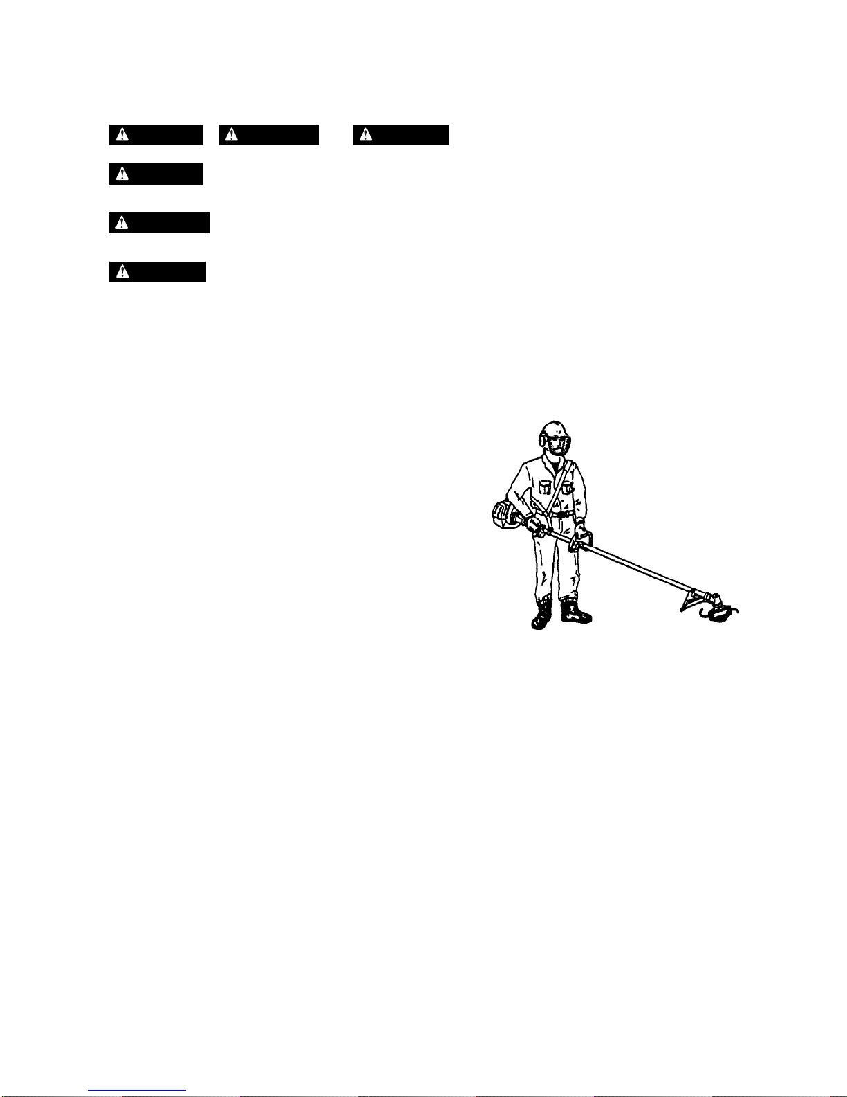
2. Always wear eye protection and hearing protection.
3. Always wear heavy long pants, a long sleeved shirt,
boots and gloves. Do not wear loose clothing,
jewelry, short pants, sandals, or go barefoot.
Secure hair so it is above shoulder length.
4. Never operate this Multi-cutter when you are tired, ill,
or under the influence of alcohol, drugs or medication.
5. Never start or run the engine inside a closed room or
building. Breathing exhaust fumes can cause death.
6. Keep the grip of handles clean of oil, fuel and dirt.
Multi-cutter safety
1. Make sure the Multi-cutter is assembled correctly and that the tool attachment is correctly installed
and securely fastened as instructed in the assembly section beginning on page 8.
2. Inspect the Multi-cutter before each use. Replace damaged parts. Check for fuel leaks.
Make sure all fasteners are in place and tightened securely. Follow the Maintenance instructions
beginning on page 25.
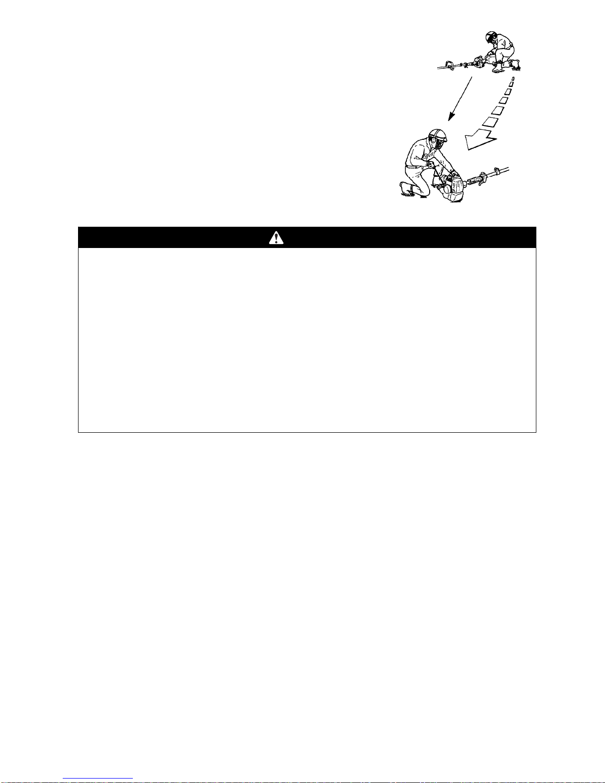
3. Shut off the engine and be certain the attached tool has completely stopped moving before
inverting the Multi-cutter, performing maintenance on or working on the machine.
4. Make sure the attached tool does not move at engine idle speed. Refer to Idle Speed Adjustment,
page 17.
5. Inspect the tool attachment and replace any parts that are cracked, chipped or damaged before
using the Multi-cutter.
6. Never use a tool attachment or replacement parts that are not approved by MARUYAMA.
7. Maintain the Multi-cutter according to the recommended maintenance intervals and procedures in
the Maintenance section beginning on page 25.
8. If running problems or excessive vibration occur, stop immediately and inspect the unit for the
cause. If the cause cannot be determined or is beyond your ability to correct, return the Multi-cutter
to your servicing MARUYAMA dealer for repair.

Fuel safety
1. Gasoline is highly flammable and must be handled and stored carefully. Use a container approved
for fuel for storing gasoline and/or fuel/oil mixture.
2. Mix and pour fuel outdoors and where there are no sparks or flames.
3. Do not smoke near fuel or Multi-cutter, or while using the Multi-cutter.
4. Do not overfill the fuel tank. Stop filling 10mm from the top of the tank.
5. Wipe up any spilled fuel before starting the engine.
6. Move the Multi-cutter at least 3m away from the fueling location before starting the engine.
7. Do not remove the Multi-cutter fuel tank cap immediately after stopping the engine.
8. Allow the engine to cool before refueling.
9. Drain the tank and run the engine dry before storing the unit.
10. Store fuel and Multi-cutter away from open flame, sparks and excessive heat. Make sure fuel
vapors cannot reach sparks or open flames from water heaters, furnaces, electric motors, etc.
Multi-cutter Operating safety
1. THIS MULTI-CUTTER CAN CAUSE SERIOUS INJURIES. Read the instructions carefully. Be
familiar with all controls and the proper use of the Multi-cutter.
2. Never allow children to operate the Multi-cutter. It is not a toy. Never allow adults to operate the
Multi-cutter without first reading this Operator’s Manual.
3. Avoid using the Multi-cutter near rocks, gravel, stones and similar material that would cause
harmful missiles.
4. Keep children, bystanders and animals outside a 15m radius
from the operator and Multi-cutter.
15m
Minimum
5. If you are approached while operating the Multi-cutter, stop
the engine and attached tool moving.
6. Use the Multi-cutter only in daylight or good artificial light.
7. Never operate the Multi-cutter without proper guards in place.
8. Do not put hands or feet near or under any moving parts. Keep clear at all times. Keep all parts of
your body away from the moving tool attachment and hot surfaces such as the muffler.
9. Keep a firm footing and balance. Do not overreach.
10. Use the right tool for the job. Do not use the Multi-cutter for any job that is not recommended by
MARUYAMA.
―4 ―
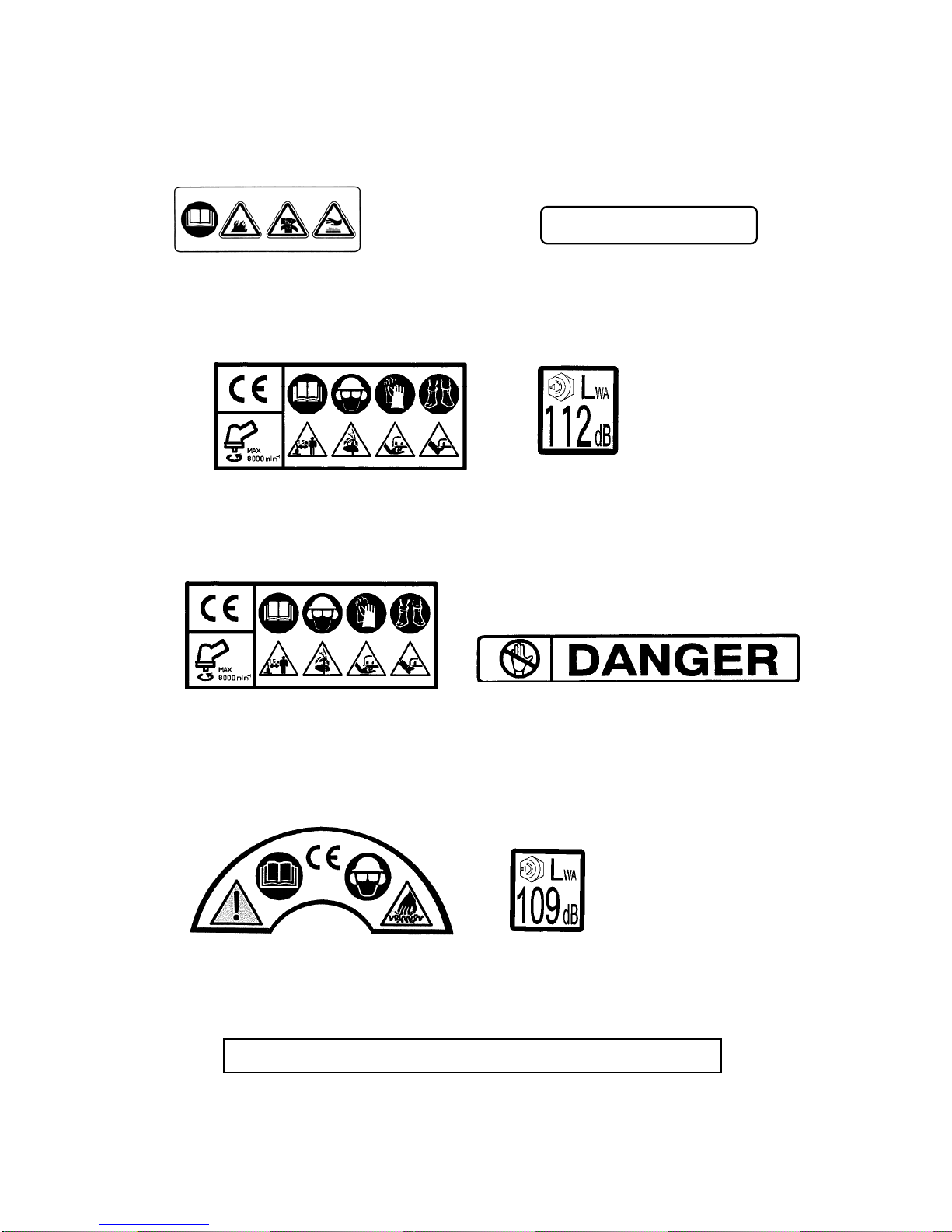
Safety and Instruction Decals
Safety decals and instructions are easily visible to the operator and are located near any
area of potential danger. Replace any that are damaged or lost.
MC2600RS (Power Unit)
Approved EC emission
ON ENGINE
(Part No. 284381)
ON ENGINE
(Part No. 284587)
MC-S (Straight Shaft Attachment)
―5 ―
MC-E (Edger Attachment)
MC-HT (Hedge Trimmer Attachment)
ON BLADE GUARD
(Part No. 221528)
ON SHAFT
(Part No. 223188)
ON SHAFT
(Part No. 223188) ON SHAFT
(Part No. 228043)
ON GEARCASE
(Part No. 220946) ON SHAFT
(Part No. 225384)
CAUTION
:Extremely sharp blades. Do not touch.
ON BLADE GUIDE PLATE
(Part No. 591450)

MC-HTS (Hedge Trimmer Attachment)
―6 ―
ON SHAFT ON SHAFT
(Part No. 225384)
ON GEARCASE
(Part No. 223188)
(Part No. 407349)
MC-PS (Pruner Attachment)
ON SHAFT
ON SHAFT (Part No. 219937)
(Part No. 223188)
MC-T (Cultivator Attachment)
ON SHAFT
(Part No. 223188)
Symbol explanation
Indicates Warning, Danger, Caution.
Read and understand this Owner’s/ Operator’s Manual.
Fire Danger: Gasoline is flammable. Never pour fuel to Multi-cutter fuel tank with the running
or hot engine. Do not smoke or place any sources of heat in the vicinity of fuel.

―7 ―
Breathing exhaust fumes cause death. Never start or run the engine inside a close room
or building.
Hot Surface Warning: Contact may cause burns. During use and some time after
stopping the engine, the engine and the gearcase are very hot. Do not touch the hot
surface of the unit such as c
y
linder, muffler and
g
earcase.
・Wear head protection, where there is a risk of falling objects.
・Wear eye protection, while operating the Multi-cutter.
・Wear ear
p
rotection, while o
p
eratin
g
the Multi-cutte
r
.
Wear gloves, while operating the brushcutter with metal blade.
Wear foot protection, while operating the Multi-cutter with metal blade.
Do not put feet near or under rotating cutting attachment.
Do not put hands near or under rotating cutting attachment.
The distance between the machine and bystanders shall be at least 15m.
Beware of thrown objects such as ricochet.
Maximum speed of output axle, min-1
Max.
8000 min-1
Always be careful to wear a face protector, ear protector and helmet when using your
Hedge Trimmer.
Keep hands away from cutting blades.
The distance between the machine and bystanders must be at least 15 m.
Guard against electric shock! Stay away from power lines.
The distance between the machine and power lines must be at least 10 m.
Guaranteed sound power level 112/109 dB(A).

Assembly
―8 ―
Screw
(
4
)
Engine
Assembling Engine and Drive Shaft Assembly
Attach the clutch drum housing to the engine using the four
screws supplied with the unit.
Clutch drum housing
Carburetor
Throttle Cam
Cable Lug
Throttle Cable
Housing
Throttle
Cable
Installing Loop Handle
L
oop handle must be assembled gearcase side from the arrow (A).
1. Place the loop handle and the bottom clamp on the shaft.
2. Install the four screws and nuts. Tighten the screws evenly.
Connecting Throttle Cable and Stop Switch Wires
1. Press up the bottom of the swivel ring to remove the swivel ring.
Note: Take care of falling the swivel ring in the engine
whenremovetheswivelring.
2. Lift up the hook, then insert the throttle cable and the cable
Loop Handle
Screw
(
4
)
Bottom Clamp
Nu
t
(4)
Swivel Ring
Hook
Throttle Cable
Housing
Guide
Screw
Recessed Hole
Cable Lug
Slotted Fitting
Slottle Cable
PUSH
Slot (Swivel Ring)
housing through the hole of the guide.
3. Turn down the hook, dab at throttle cable housing, then
tighten up a screw.
4. Position the slotted fitting on the carburetor so the
recessed hole for the lug is away from the hook side.
5. Rotate the carburetor throttle cam and slip the throttle
Cable through the slot in the slotted fitting, making sure
the cable lug drops into the recessed hole.
6. Align the slot of the swivel ring with the slottle wire, then
press down the swivel ring and fix.
Note: Take care of falling the swivel ring in the engine
whenremovetheswivelring.

7. Operate the throttle trigger a few times to make sure that
it works correctly.
Sto
p
Switch Wires
8. Plug the stop switch wires into the matching connectors
from the engine. Note that wire polarity is not important.
Clam
p
9. Hold the stop switch wires with the clamp.
MC-S (Straight Shaft Attachment)
Installing Guard
Fig.1
Plate
Blade Guard
Gearcase
WARNING
POTENTIAL HAZARD
・Foreign objects can be thrown by Multi-cutter.
WHAT CAN HAPPEN
・Contact with thrown objects can cause personal injury.
HOW TO AVOID THE HAZARD
・Never operate the Multi-cutter without the guard in place.
Blade Guard
Attach the blade guard to the gearcase with the Plate as
shown on Fig. 1. Guard
extension
Square nu
t
Trimmer Head Guard
(Install the string cutoff blade and guard extension to the blade
guard.)
1. Insertthe squarenutinto guard extension as shown on Fig. 2.
Fig.2
2.AttachtheString Cutoff Blade to guard extension using
M5×20 Screw, locking with square nut (on Fig.2) as shown
―9 ―
on Fig. 3 .
3. Enter the guide in the slot of Blade Guard on Fig. 4.
Make sure place the three hooks into the position
Hook
Blade Guard
Guard extension
Guide
Fig.4
String Cutof
f
Blade
M5×20
Screw
Fig.3
on the guard as shown on Fig. 5.
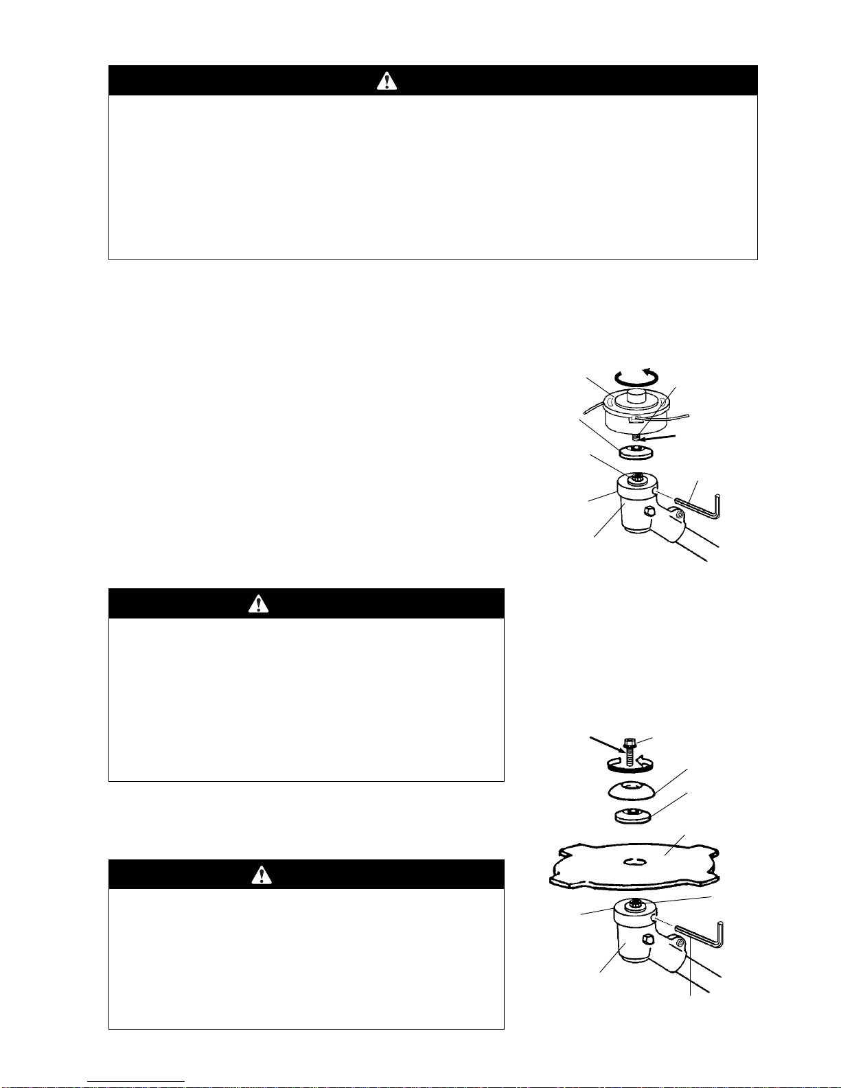
Installing Trimmer Head
WARNING
POTENTIAL HAZARD
・If the cutting attachment is not adequately tightened, it can come loose from the Straight
Shaft Attachment during use.
WHAT CAN HAPPEN
・This may cause damage to property or personal injury.
HOW TO AVOID THE HAZARD
・Make sure the cutting attachment head is securely fastened to the attaching shaft in the
gearcase.
IMPORTANT: Make sure the trimmer head is for LEFT-HAND ROTATION (counterclockwise) as viewed
from the operator’s position, and that the trimmer head adapter is a male, M8 left-hand thread.
1. Align the hole in the boss adapter with the guide slot in the
gearcase. Trimmer Head Trimmer Head
Adapter
Attaching
Shaft
Gearcase
Boss
Adapter
3mm
Hex Wrench
Washe
r
Left-hand
thread
2. Insert the φ3.5mm pin into the hole in the boss adapter
and the guide slot in the gearcase to lock the attaching shaft.
3. Thread the trimmer head adapter into the attaching shaft,
then tighten the trimmer head by hand.
Note: The trimmer head adapter has left-hand thread.
4. Remove the 3mm hex wrench from the boss adapter and
gearcase.
Installing Brushcutter Blade
―10 ―
WARNING
POTENTIAL HAZARD
・If the Brushcutter blade is not adequately tightened, it
can come loose from the Brushcutter during use.
WHAT CAN HAPPEN
・This may cause damage to property or personal injury.
HOW TO AVOID THE HAZARD
・Make sure the Brushcutter blade is securely fastened
to the attaching shaft in the gearcase.
Brushcutter Blade
Washe
r
Stabilize
r
Blade Bol
t
Left-hand
thread
Gearcase
Boss
Adapter
Boss
Adapter
3mm Hex Wrench
1. Remove the blade bolt, stabilizer and clamping washer
from the attaching shaft out of the gearcase.
Note: The blade bolt has left-hand thread.
CAUTION
POTENTIAL HAZARD
・Brushcutter blade is sharp.
WHAT CAN HAPPEN
・Contact with sharp blade can cause personal injury.
HOW TO AVOID THE HAZARD
・Wear gloves when you handle the blade.

2. Install the brushcutter blade onto the boss adapter, then reinstall the clamping washer, stabilizer and
blade bolt.
3. Align the hole in the boss adapter with the guide slot in the gearcase.
4. Insert the 3mm hex wrench into the hole in the boss adapter and the guide slot in the gearcase to lock
the attaching shaft.
5. Tighten the blade bolt.
6. Remove the φ3,5mm pin from the boss adapter and gearcase.
MC-E (Edger Attachment)
Installing Guard
Guard
Lock Washe
r
He
x
Loc
k
Washer
Fla
t
Washe
r
Colla
r
Flat
Washer
Knob
Plate
WARNING
POTENTIAL HAZARD
・Foreign objects can be thrown by Edger.
WHAT CAN HAPPEN
・Contact with thrown objects can cause personal injury.
HOW TO AVOID THE HAZARD
・Never operate the Edger without the blade guard.
1. Install the collar onto the plate stud.
2. Install the guard onto the plate stud, making sure the guard stud Plate Stud
fits into the matching slot in the plate.
3. Install the flat washer, lock washer and hex nut onto the plate stud.
4. Install the flat washer and knob onto the guard.
―11 ―
WARNING
POTENTIAL HAZARD
come loose from the Edger during use.
WHAT CAN HAPPEN
・This may cause damage to property or personal injury.
HOW TO AVOID THE HAZARD
・Make sure the Edger blade is securely fastened to the
attaching shaft in the gearcase.
・If the Edger blade is not adequately tightened, it can
Edger Blade
Blade Bol
t
Gearcase
3mm
hex wrench
Attaching
Shaf
t
Boss
Left-hand
thread
1. Install the boss onto the attaching shaft out of the gearcase.
2
. Install the edger blade, clamping washer and blade bolt.
Note: The blade bolt has left-hand thread.
3. Align the hole in the boss adapter with the guide slot in the gearcase.
4. Insert the 3mm hex wrench into the hole in the boss adapter and the guide slot in the gearcase to lock
the attaching shaft.
5. Tighten the blade bolt to 11.3 Nm.
6. Remove the 3mm hex wrench from the boss adapter and gearcase.
MC-PS (Pruner Attachment)
―12 ―
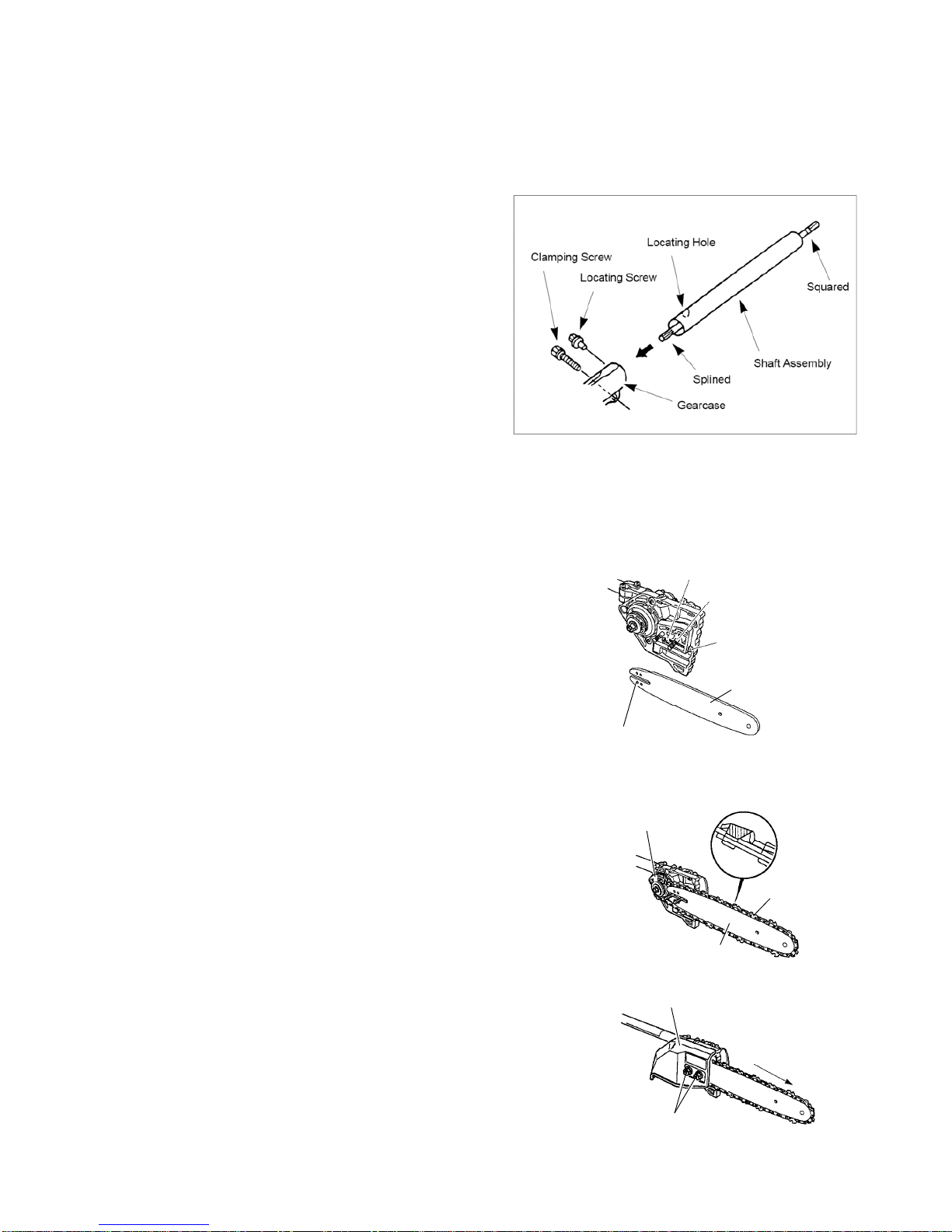
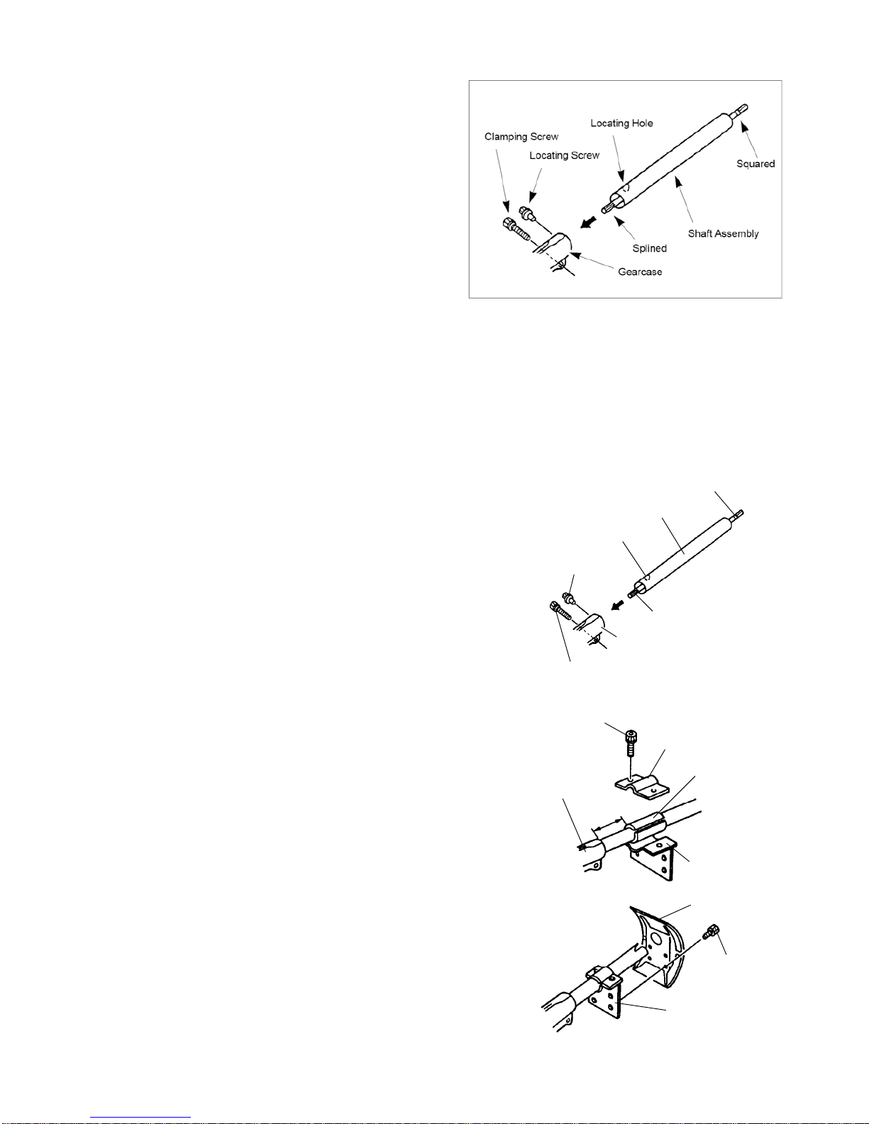
Installing Shaft and Gearcase
Attach the driveshaft tube assembly to the gearcase
assembly.
NOTE: Carefully inspect both ends of the drive-
shaft protruding from the driveshaft tube.
The squared end of the driveshaft positions
toward the connector of the power unit.
The splined end of the driveshaft connects
to the gearcase assembly.
Insert the driveshaft tube assembly into the
gearcase assembly while rotating the drive-
shaft to engage the splines. Align the locating holes and install the locating screw through
the side of the gearcase. Then tighten the clamping screws. If properly installed, ro-tating
the square end of the driveshaft will cause the Rim sprocket to turn.
Installing Guide Bar and Chain
Guide Ba
r
Chain Tensioner
Adjustment
Pin Hole
Chain Tensioner
Screw
Bar Stud
(
2
)
Chain Tensioner
Adjustment Pin
1. Remove the nuts from the two bar studs.
2. Fit the guide bar over the two bar studs. Do not engage the
chain tensioner adjustment pin hole at this time.
3. place the chain over the rim sprocket and into the groove on
the guide bar. Make sure the cutting teeth edges are facing
forward on the top side of the guide bar.
4. Pull the guide bar forward until the chain tensioner adjustment
pin hole is positioned over the chain tensioner adjustment pin.
If necessary, turn the chain tensioner screw in the appropriate
direction to align the pin with the hole. Check that the drive links
on the chain fit correctly into the rim sprocket and guide bar
groove. Rim Sprocket
Chain
Guide Ba
r
5. Install the sprocket cover onto the two bar studs. Install the bar
stud nuts, but leave the nuts finger-tight.
6. Rotate the chain tensioner screw until all slack is removed
between the chain and the bottom of the guide bar, but loose
enough to allow you to pull the chain around the guide bar by
hand.
7. Tighten the bar stud nuts and recheck the chain tension.
IMPORTANT: When using a new chain, you must check the Sprocket Cove
r
Bar Stud Nuts
Chain Travel
Direction
chain tension frequently and adjust the tension as
necessary until the chain breaks in.
A correctly adjusted chain gives optimum cutting
performance and prevents premature wear to both the
chain and guide bar.
MC-HTS (Hedge Trimmer Attachment)
Installing Shaft and Gearcase
―13 ―
Attach the driveshaft tube assembly to the gearcase
assembly.
NOTE: Carefully inspect both ends of the drive-
shaft protruding from the driveshaft tube.
The squared end of the driveshaft positions
toward the connector of the power unit.
The splined end of the driveshaft connects
to the gearcase assembly.
Insert the driveshaft tube assembly into the
gearcase assembly while rotating the drive-
shaft to engage the splines. Align the locating
holes and install the locating screw through
the side of the gearcase. Then tighten the
clamping screws. If properly installed, ro-
tating the square end of the driveshaft will
cause the blades to move.
MC-T (Cultivator Attachment)
Installing shaft and Shield Squared
Splined
Locating Hole
Clamping Screw
Locating
Screw
Gearcase
Shaft Assembly
1. Attach the driveshaft tube assembly to the cultivator gearcase
assembly.
NOTE: Carefully inspect both ends of the driveshaft
protruding from the driveshaft tube. The squared end of
the driveshaft positions toward the connector of the power
unit. The splined end of the driveshaft connects to the
cultivator gearcase assembly. Insert the driveshaft tube
assembly into the cultivator gearcase assembly while
rotating the driveshaft to engage the splines. Align the
locating holes and install the locating screw through
the side of the gearcase. Then tighten the clamping
Bracket
Bracket
2.5cm
Gearcase
Screw 6mm(2)
Plastic Colla
r
screws. If properly installed, rotating the square end of
the driveshaft will cause the cultivator tines to turn.
2. Place the plastic collar onto the driveshaft tube
approximately 2.5cm from the cultivator gearcase, locating
the ends as shown in sketch. Then place the two bracket
parts onto the plastic collar and fasten securely with two
6 mm screws. Attach the guard to the bracket with four
5 mm screws.
Bracket
Guard
Screw
5mm(4)
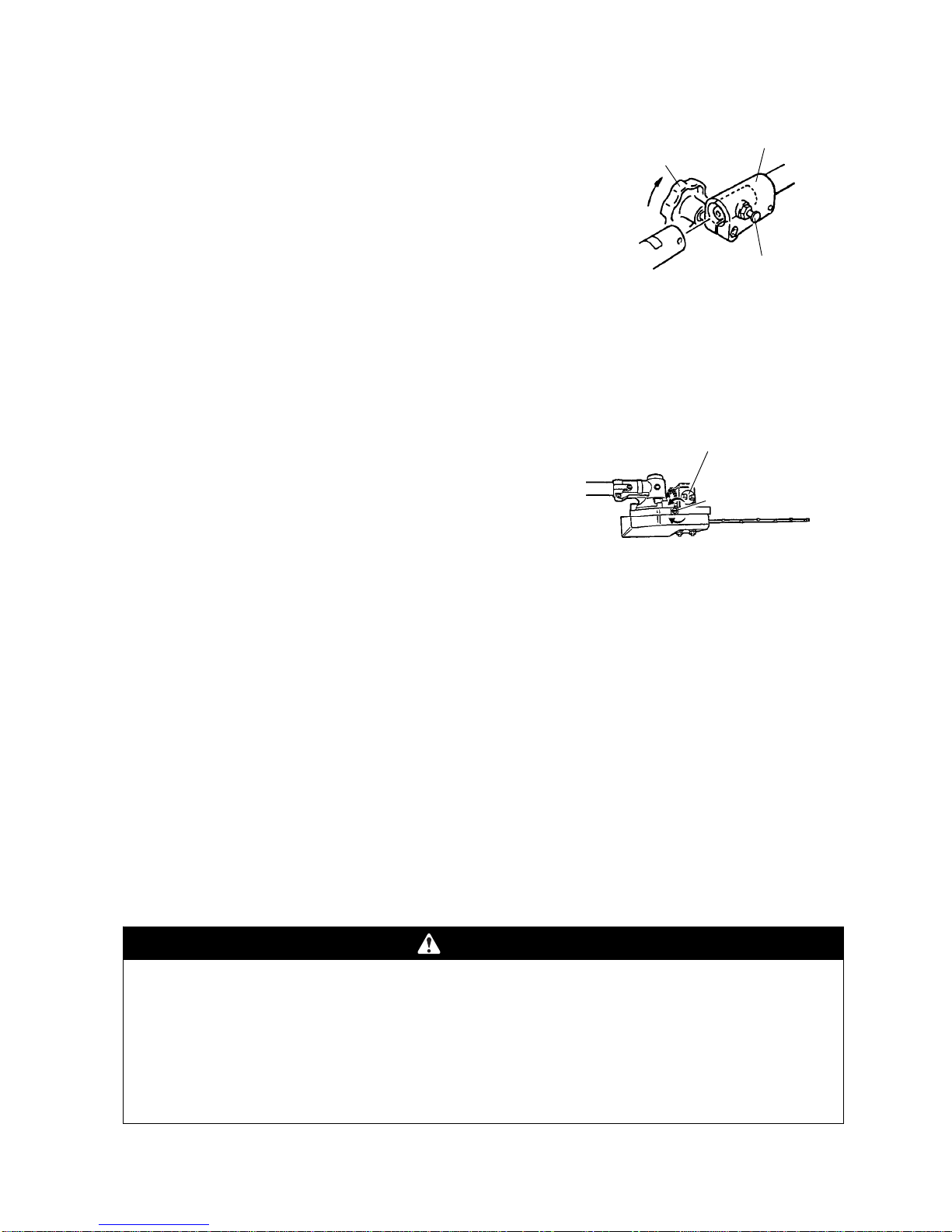
Connecting the Tool Attachment to the Power Unit
First, loosen the clamping knob so shaft of the tool attachment
Clamping Knob
Detent Knob
Tube
Coupler
Loose
can be inserted into the tube coupler. Pull the detent knob
outward and gently rotate attachment shaft back and forth while
inserting to be sure the driveshafts completely in place. The
spring loaded detent knob will snap into place when the
attachment shaft is correctly positioned. Tighten the clamping
knob. When changing the tool attachment be careful not to over
loosen the clamping knob to prevent it from falling.
Before Operation
Chain Oil (Pruner Attachment)
―14 ―
The chain and guide bar are lubricated by a centrifugal pump.
The oil discharge rate is controlled by the oil discharge Oil Discharge
Adjustment Screw
Oil Tank Filler Cap
adjustment screw on the top of the pruner head. Remove the
oil tank filler cap fill the tank, then replace the cap.
IMPORTANT: Only use oil designed for lubricating chain saw chains and guide bars. Do not use
waste oil. Never run the chain dry. In temperatures below freezing, check the chain oil viscosity
(pour point). If the oil is not rated for use below freezing, it may not provide adequate lubrication,
resulting in damage to the oil pump, chain and guide bar.
IMPORTANT: When filling the oil tank for the first time, or when the tank is completely empty, wait
approximately 60-90 seconds before starting the Pruner. This will give the oil time to flow from the
tank to the pump. Otherwise, an air lock can occur which will prevent oil from moving through the
pump. This will result in damage to the chain and guide bar.
Engine Oil and Fuel
1. Mix and pour fuel outdoors and where there are no sparks or flames.
2. Always shut off the engine before refueling. Never remove the Multi-Cutter fuel tank cap while the
engine is running or immediately after stopping the engine.
WARNING
POTENTIAL HAZARD
・Gasoline contains gasses that can build up pressure inside a fuel tank.
WHAT CAN HAPPEN
・fuel can be sprayed on you when removing fuel tank cap.
HOW TO AVOID THE HAZARD
・Remove fuel tank cap slowly to avoid injury from fuel spray.
―15 ―
3. Always open the fuel tank cap slowly to release any possible
pressure inside the tank.
4. Do not overfill the fuel tank. Stop filling 10mm from the top of the
3m
Minimum
tank.
5. Tighten the fuel tank cap carefully but firmly after refilling.
6. Wipe up any spilled fuel before starting the engine.
7. Move the Multi-Cutter at least 3m away from the fueling location
and fuel storage container before starting the engine.
DANGER
approved container and keep it out of the reach of children.
・Do not mix fuel for more than two month use.
・Do not fill the fuel tank completely. Add gasoline to the fuel tank until the level is 10mm
below the bottom of the filler neck. This empty space in the tank allows gasoline to expand.
・Never smoke when handling gasoline, and stay away from an open flame with gasoline in an
Wipe up any gasoline that spills.
POTENTIAL HAZARD
・In certain conditions gasoline is extremely flammable and highly explosive.
WHAT CAN HAPPEN
・A fire or explosion from gasoline can burn you, others and cause property damage.
HOW TO AVOID THE HAZARD
・Use a funnel and fill the fuel tank outdoors, in an open area, when the engine is cold.
Recommended Oil Type
Only use a two-cycle engine oil formulated for use in high-performance, air-cooled two-cycle engines.
IMPORTANT: Do not use two-cycle oil intended for water cooled outboard motors. This type of
two-cycle engine oil does not have the additives for air-cooled two-cycle engines and can cause
engine damage.
Do not use automotive motor oil. This type of oil does not have the proper additives for
air-cooled two-cycle engines and can cause engine damage.
Recommended Fuel Type
Use clean, unleaded gasoline with an octane rating of 85 or higher. Use of unleaded gasoline results in fewer
combustion chamber deposits and longer spark plug life. Use of premium grade fuel is not necessary or
recommended.
IMPORTANT: Never use gasohol or alcohol blended fuels in this engine.

Mixing Gasoline and Oil
IMPORTANT: The engine used on this Multi-cutter is of a two-cycle design. The internal
moving parts of the engine, i.e., crankshaft bearings, piston pin bearings and piston to cylinder
wall contact surfaces, require oil mixed with the gasoline for lubrication.
Failure to add oil to the gasoline or failure to mix oil with the gasoline at the appropriate ratio will
cause major engine damage which will void your warranty.
Fuel Mixture
The fuel: oil ratio is 25 parts gasoline to 1 part oil or 25:1.
Fuel Mixture Chart 25:1 Gasoline two-cycle oil
1litre 40ml
2litre 80ml
5litre 200 ml
Mixing Instructions
IMPORTANT: Never mix gasoline and oil directly in the Multi-cutter fuel tank.
1. Always mix fuel and oil in a clean container approved for gasoline.
2. Mark the container to identify it as fuel mix for the Multi-cutter.
3. Use regular unleaded gasoline and fill the container with half the required amount of gasoline.
4. Pour the correct amount of oil into the container then add the remaining amount of gasoline.
5. Close the container tightly and shake it momentarily to evenly mix the oil and the gasoline before filling
the tank on the Multi-cutter.
6. When refilling the Multi-cutter fuel tank, clean around the fuel tank cap to stop dirt and debris from
entering the tank during cap removal.
7. Always shake the premix fuel container momentarily before filling the fuel tank.
8. Always use a spout or funnel when fueling to reduce fuel spillage.
9. Fill the tank only to within 10mm from the top of the tank. Avoid filling to the top of the tank filler neck.
Starting and Stopping
Before Starting the Engine
1. Fill the fuel tank as instructed in the Before Operation section of Starter grip
Fuel return line
Primer
bulb
this manual.
2. Rest the Multi-cutter on the ground.
3. Make sure the cutting attachment is clear of any broken glass,
nails, wire, rocks or other debris.
4. Keep all bystanders, children and animals away from the working
area.
―16 ―
―17 ―
Cold Starting Procedure
The carburetor on this engine contains a choke system.
To start a “cold” engine properly, perform the following
procedure:
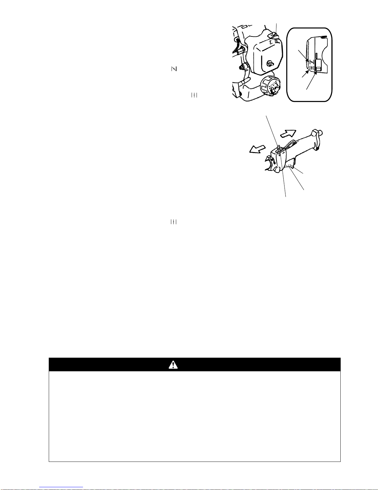
1. Turn the choke lever to the Close position“
”.
2. With the stop switch “ON” , and the throttle trigger positioned at
Fast-idle start position, pull the starter grip. After the engine is
started, turn the choke lever to the Open position “
”.
Then squeeze and release the throttle trigger to allow it to return
Close
O
p
en
Choke lever
Choke lever
STOP
(
OFF
)
Stop switch
START
(
ON
)
Fast-idle start
position
Idle position
Fast-idle start lock
to the idle position.
If the engine stops running before you turn the choke lever to the
open position :
Go ahead and open the choke, pull the starter grip with the throttle
trigger positioned at Fast-idle start position.
Hot Restart
To start the engine that is already warmed up (hot restart).
1. Turn the choke lever to the open position “
”, and set the stop switch to the “ON” position.
2. Leave the throttle trigger in the idle position and pull the starter grip.
3. If the engine fails to start after three to four pulls, follow the instructions in the Cold Starting Procedure
section above.
If the engine fails to start after you follow the above procedures, contact an authorized MARUYAMA
dealer.
To Stop the Engine
1. Release the throttle trigger.
2. Slide the stop switch to “STOP” position.
Idle Speed Adjustment
This Multi-cutter is equipped with non-adjustable fuel mixture carburetor. The idle speed is the only
adjustment for the operator.
WARNING
POTENTIAL HAZARD
・When engine is running, attached tool and other parts are moving.
WHAT CAN HAPPEN
・Contact with moving attached tool or other moving parts could cause serious personal injury
or death.
HOW TO AVOID THE HAZARD
・Keep hands, feet and clothing away from attached tool and other moving parts.
・Keep all bystanders and pets away from unit while making carburetor adjustments.
・Engine must be running to make carburetor adjustments.

Idle Speed Adjustment Scre
w
The attached tool may be moving during idle speed adjustment.
Wear the recommended personal protective equipment and
observe all safety instructions.
Keep hands and body away from the attached tool.
When the throttle trigger is released, the engine should return
to an idle speed. The correct speed is 2700 - 3300 min-1 (or just
below the clutch engagement speed ). The attached tool must not
move and the engine should not stall (stop running) at engine idle
speed.
To adjust the engine idle speed, rotate the idle speed adjustment screw on the carburetor.
・Turn the idle speed screw in (clockwise) to increase the engine idle speed.
・Turn the screw out (counterclockwise) to decrease the engine idle speed.
If idle speed adjustment is necessary, and after adjustment the cutting attachment rotates or the
engine stalls, stop using the Multi-cutter immediately!
Contact your local authorized MARUYAMA Dealer for assistance and servicing.
Operation
MC-S (Straight Shaft Attachment)
―18 ―
WARNING
POTENTIAL HAZARD
・Foreign objects can be thrown by Multi-cutter.
WHAT CAN HAPPEN
・Contact with thrown objects can cause personal injury.
HOW TO AVOID THE HAZARD
・Never operate the Multi-cutter without the cutting attachment guard in place.
CAUTION
・Read the Safety instructions beginning on page 3 concerning proper use of the Multi-cutter.
・Alwa
y
s wear
g
loves and
p
rotective clothin
g
when o
p
eratin
g
the Multi-cutte
r
.
Operating Position
Before using the Multi-Cutter with Straight Shadt Attachment, check the following:
WARNING
POTENTIAL HAZARD
・Without the shoulder strap installed, the Brushcutter blade can produce side thrust
which can expose the operator and bystanders to blade contact.
・If the Multi-cutter is not correctly positioned on the operator’s right side, the blade can
produce side thrust which can expose the operator and bystanders to blade contact.
WHAT CAN HAPPEN
・Contact with the Brushcutter blade can cause severe personal injury.
HOW TO AVOID THE HAZARD
・Never operate the Multi-cutter without installing and using the shoulder strap.
・Always operate the Multi-cutter with the unit on your right side.

Shoulder
Hanging Strap
1. The unit should be on the operator’s right side. The operator’s right
hand should be holding the shaft grip, with his or her fingers on
the throttle trigger. The right arm should be slightly bent.
2. The left hand should be holding the loop handle with the fingers
and thumb fully enclosed around the grip. The left arm should
be extended. Reposition the loop handle up or down the
driveshaft if necessary for a comfortable position.
3. The Trimmer weight should be evenly distributed between the
arms. The trimmer head should be near and parallel to the
ground. Stra
p
Ring
Red Band
Pull
4. Accelerate and hold the engine at cutting speed before entering
the material to be cut.
5. Always release the throttle trigger and allow the engine to return
to idle speed when not cutting.
6. Stop the engine when moving between work sites.
・If the trimmer head becomes jammed, stop the engine
immediately.
・Make certain all moving parts have stopped and disconnect the
spark plug before inspecting the equipment for damage.
・Never use a unit that has a chipped, cracked or broken trimmer
head.
・Snap the strap hook into the ring on the drive shaft. To detach
the strap quickly from the unit, pull upward on red band.
Trimmer Head
・The tip of the line does the cutting. The line should stay
extended while cutting.
WARNING
POTENTIAL HAZARD
direction.
WHAT CAN HAPPEN
・Use of improper line could result in serious personal injury.
HOW TO AVOID THE HAZARD
・Use only good quality, commercial grade, weld resistant trimmer line with a diameter of 2,4mm.
・Do not use any type of wire or other string-like substance. Do not use metal-reinforced line.
・Use of improper line could cause line to break and be thrown in operator’s or bystander’s
5
-
10cm above
Ground
CORREC
T
・Do not force the line into the material. Forcing the line
will cause it to slap against the material, increasing line
usage and causing poor cutting results.
INCORREC
T
―19 ―
Other manuals for MC2600RS
1
This manual suits for next models
6
Table of contents
Other Maruyama Cutter manuals

Maruyama
Maruyama M42BK-QC Owner's manual

Maruyama
Maruyama M27QC Owner's manual

Maruyama
Maruyama QC-S User manual

Maruyama
Maruyama QC-HT User manual

Maruyama
Maruyama QC-E User manual

Maruyama
Maruyama BM240 Owner's manual

Maruyama
Maruyama M30BK-S User manual

Maruyama
Maruyama QC-PS User manual

Maruyama
Maruyama M270QC Owner's manual
Popular Cutter manuals by other brands


STAMOS
STAMOS S-PLASMA 70-IGBT user manual

REXON
REXON MC1850R instruction manual

Lincoln Electric
Lincoln Electric ESSENTIAL OXYCUTTING Safety instruction for use and maintenance

Makita
Makita 4112HS instruction manual

Milwaukee
Milwaukee 49-40-6110 Operator's manual

Martor
Martor SECUNORM HANDYCUT quick start guide