ICS-KP14 Instruction Manual
01850-53-000 Page 5 of 18 Issue 3 19 January 2021
3 Concept
The ICS-KP14 Keypad is intended to be used in conjunction with Lasermet’s Laser Interlock systems
for the purpose of inhibiting access to a hazardous area to unauthorised persons. Normally this means
persons without the necessary training and personal protective equipment for the area concerned.
The keypad is sited outside a door which is electrically locked and monitored by the interlock system.
The keypad is not intended to be used as part of a security system.
The keypad has two timers which may be programmed to activate for a defined time interval when
the correct 4-digit user code is entered. When wired into a Lasermet interlock system, one output is
used to unlock the door and one to activate the override function to allow the door to be opened
without tripping out the laser.
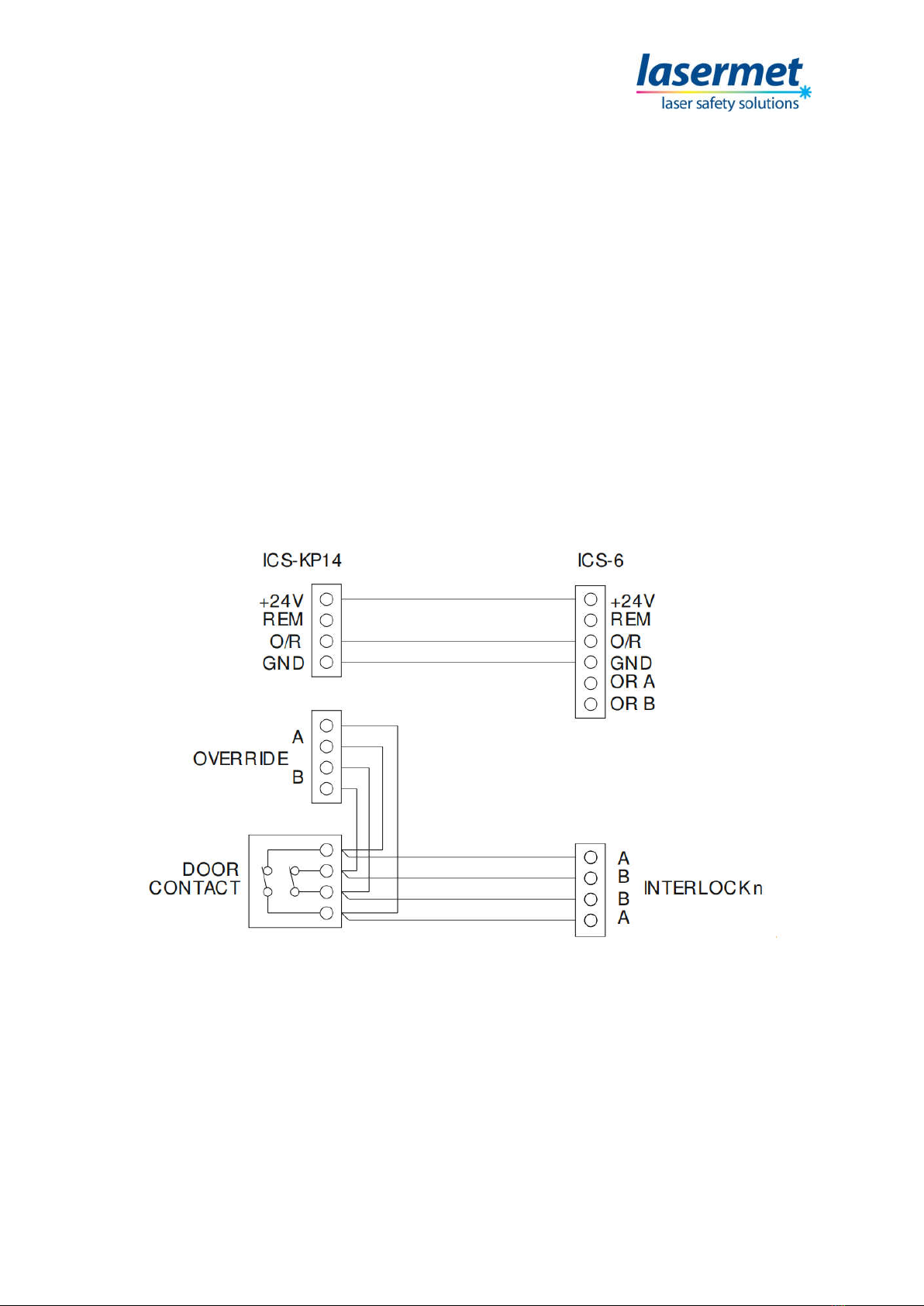
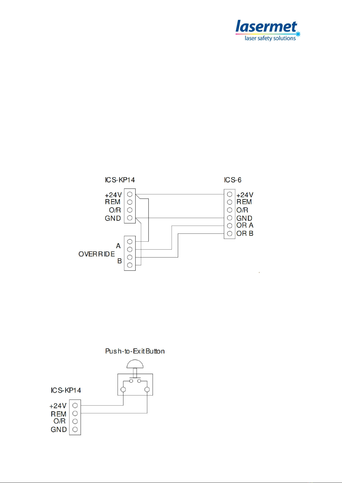
The keypad may either be wired to the interlock control panel to override all the door switches, or to
the contacts of the adjacent door such that only one door is defeated. It is possible to program the
keypad to disable either of the timer outputs. This may be used for example where the door is not
fitted with an electric lock, in which case the door lock function would be disabled.
The override timer function is of a dual-channel cross-checked configuration and is designed to
achieve a safety performance level of PL ‘e’ to EN13849 when correctly wired to a suitable interlock
system.
Lasermet provides a full range of laser interlock equipment including control systems, interlock
switches, illuminated warning signs, laser shutters, door locks, external power supplies etc. which can
be connected to provide a complete laser interlock system. Full support, design and installation is
available from Lasermet, please contact us for any queries. Contact details are given at the end of this
manual.
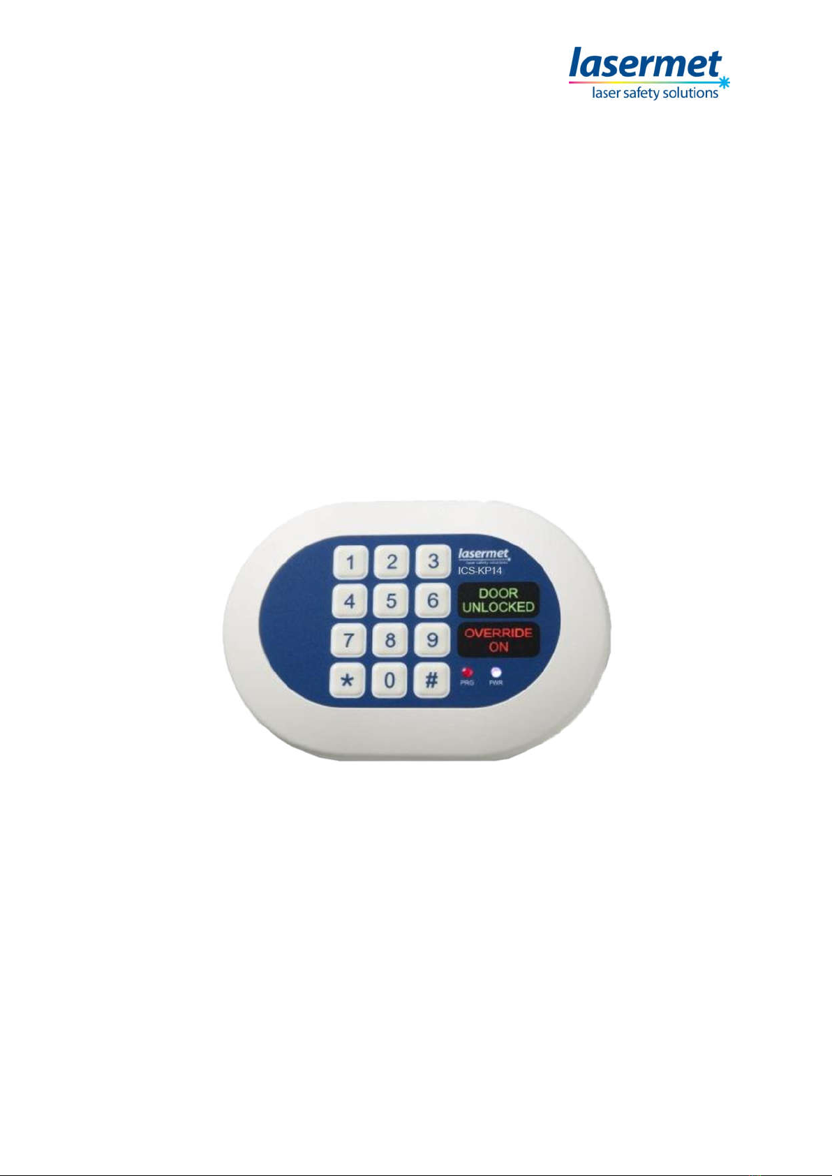
3.1 Configuration Options
The ICS-KP14 Keypad has two outputs which activate for a set time when the correct 4-digit user code
is entered: the Override output and the Door Unlock output. Each output illuminates a corresponding
indication on the keypad when activated.
Each output may be independently programmed to activate for a set time between 1 and 30 seconds
when the correct code is entered on the keypad. An output is disabled by programming it to operate
for 0 seconds.
For laser interlock systems in which the entry door is electrically locked, e.g. by a maglock, the Door
Unlock output should be used to release the door, and the Door Unlock time should be programmed
for the required door lock release time.
If there is no electric lock on the door, the Door Unlock output is not used and the Door Unlock time
should be set to 0 to disable the indication on the keypad.