Monitored Maglock Instruction Manual
CEB00XXX-53-000 Page 4 of 8 Issue 2 13 January 2020
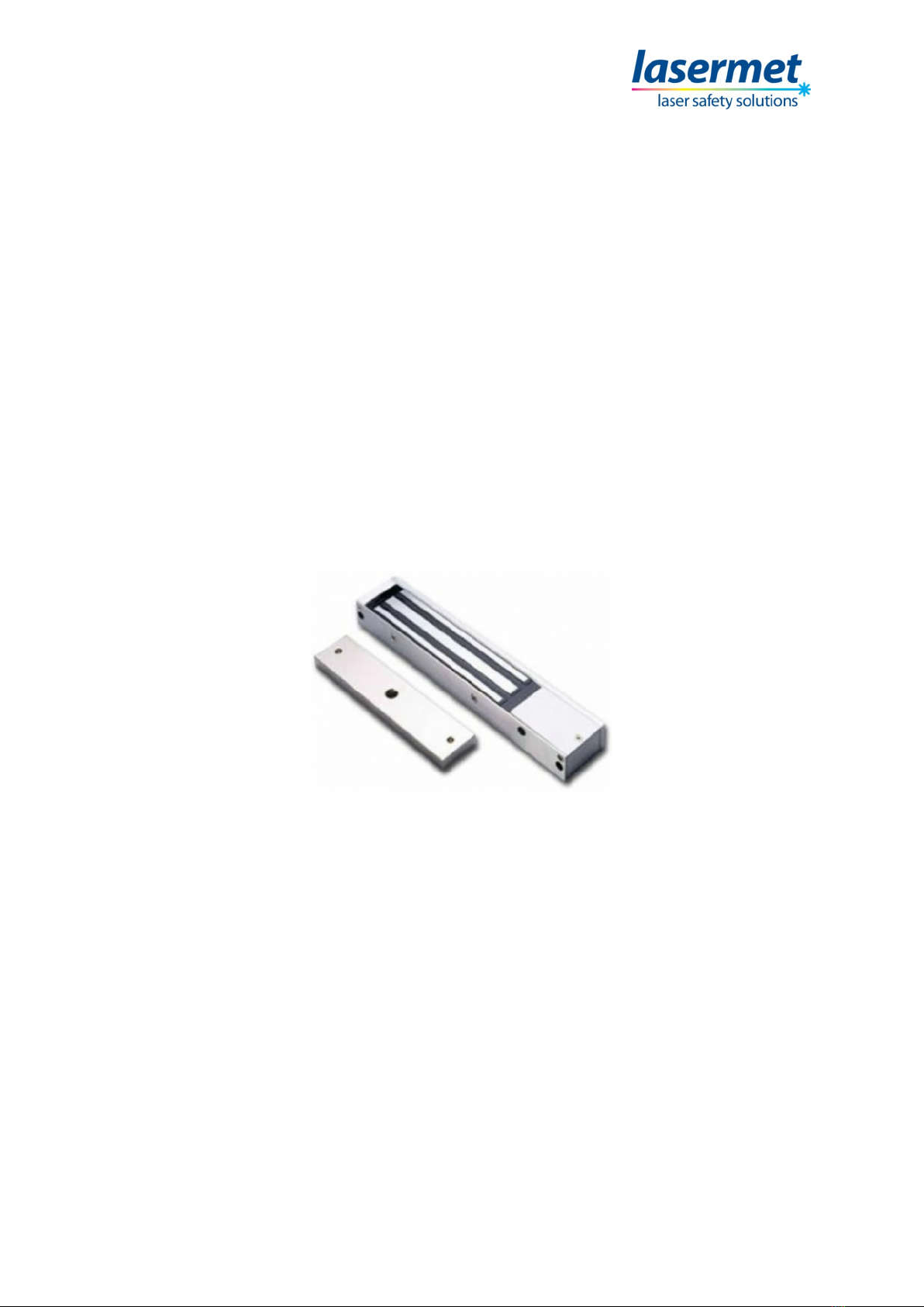
2 Concept
Suitable for internal doors, this maglock has an aluminium finish and it is monitored so that the
status of the door locking mechanism can be confirmed.
When the maglock is energised and the door is closed, the onboard relay is closed and a green LED
illuminates.
When the maglock is energised and the door is NOT closed, the onboard relay is open and a red LED
illuminates.
Lasermet provides a full range of laser interlock equipment including control systems, interlock
switches, illuminated warning signs, laser shutters, door locks, external power supplies etc. which
can be connected to provide a complete laser interlock system. Full support, design and installation
is available from Lasermet, please contact us for any queries. Contact details are given at the end of
this manual.
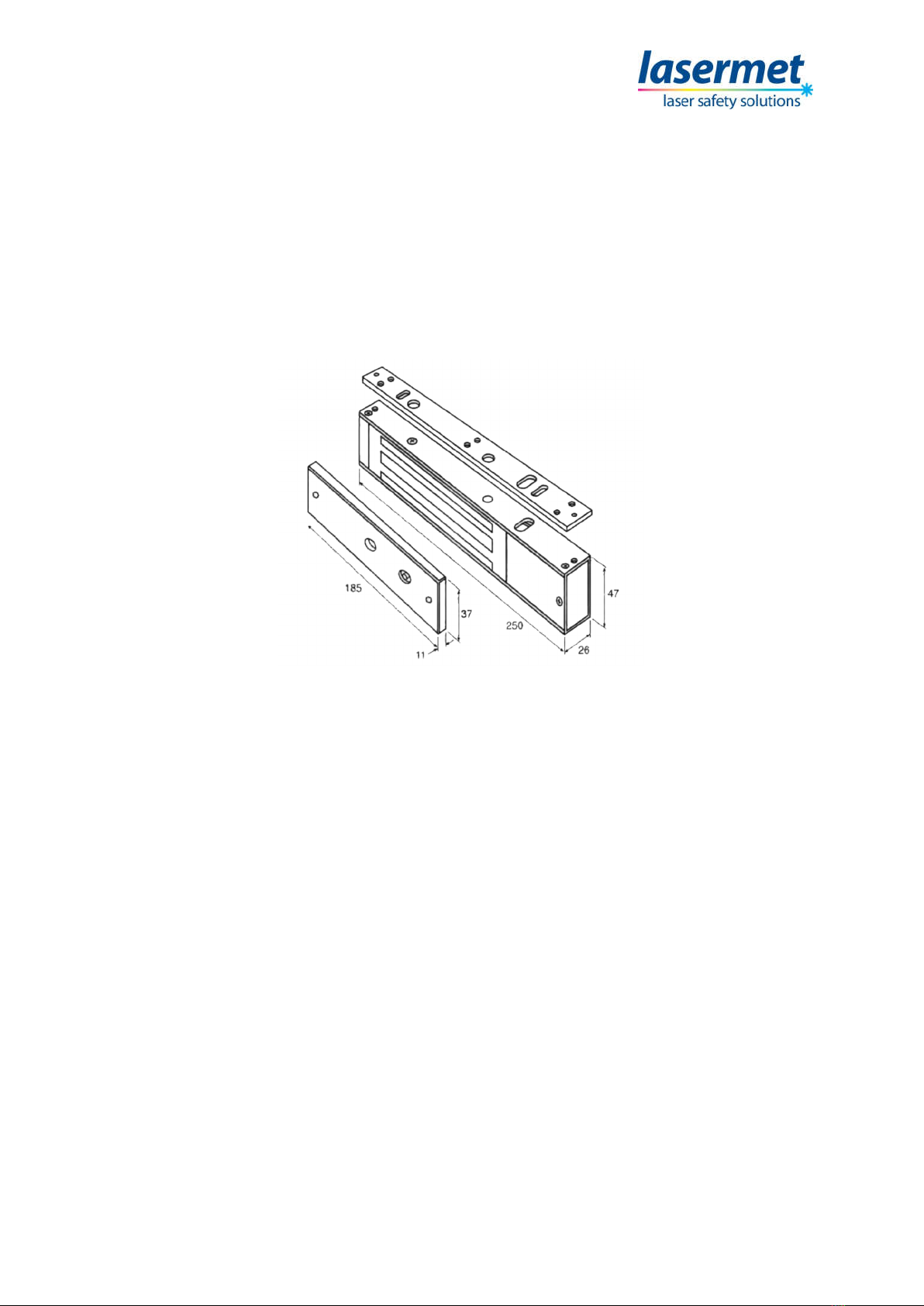
3 Installation
Handle the equipment with care, damaging the mating surfaces of the magnet or armature plate
may reduce locking efficiency.
The magnet mounts rigidly to the door frame, the armature plate mounts to the door with the
hardware kit provided. This allows it to pivot about its centre to compensate for door wear and
misalignment.
The template must be used when the door is in the closed position.
Before installing, add thread locker to all screws. Firmly tighten screws.
NOTE: Fix the armature plate lightly to ensure the rubber washer remains flexible. This enables the
armature plate to automatically adjust to its correct position with the magnet.
Typical Installation