Page 01
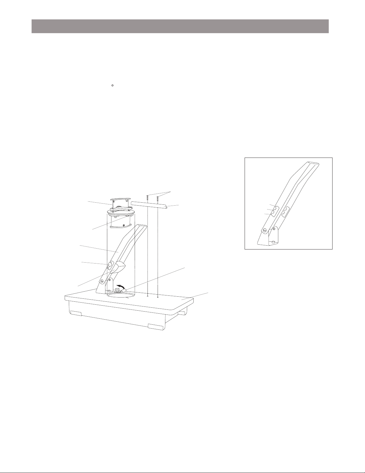
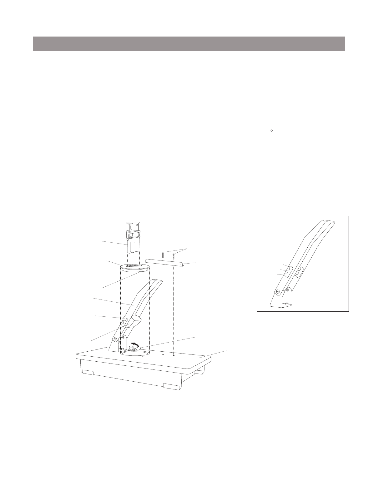
Adapter Plate (50-26) Side Guide (50-03R)
Adapter Plate Rotation Tab (50-12)
Wooden Top Plate (50B-01)
Adapter Hold Down Tab (50-11)
Standard / Special Size
Cutting Unit (Misc Part #’s)
Thumb Screw Knob (50B-12)
Pivot Bracket (50B-07)
Handle (50B-05)
Operating Instructions
Push down and pull back on the two Thumb Screw Knobs (50B-12) on both sides of the
Handle (50B-05) Until the Pivot Bracket (50B-07) is engaged in the last Slot #3 of the
Handle.
Raise the Handle to the maximum position.
Insert the Adapter Plate (50-26) into the Wooden Top Plate (50B-01) making sure to line up
the red guides. Make sure that the Adapter Plate Rotation Tab (50-12) slips under the
Wooden Top Plate into its designated groove to prevent unwanted rotation of the Adapter
Plate. Turn the Adapter Hold Down Tab (50-11) so that it locks the Adapter Plate into
place.
Insert the Cutting Unit into the Adapter Plate by tilting it approximately 45 forward and
seating it by pushing back and down until it is secure in place.
Push down and pull back on the two Thumb Screw Knobs and move the Pivot Bracket into
Slot #1 of the Handle as shown below.
Depress the Handle up and down a few times to check the action of the Cutting Unit. Make
sure the Pivot Bracket is correctly coming down onto the Cutting Unit.
Align the Side Guide (50-03R) using a straight edge pushed into the corner of the Cutting
Unit. When it is positioned as desired, tighten down the Side Guide using the two
6-32 x 3/4” Pan Head Slotted Machine Screws.
Cutting Unit Installation (Special & Standard Sizes)
1.
2.
3.
4.
5.
6.
7.
6-32 x 3/4” Pan Head Slotted
Machine Screws
Note: When using a Standard or Special Size Cutting Unit it is important that the Pivot Bracket is located in
the Handle Slot #3 during operation. If the Pivot Bracket is located in either of the other two Slots, you
can damage the Cutting Unit.
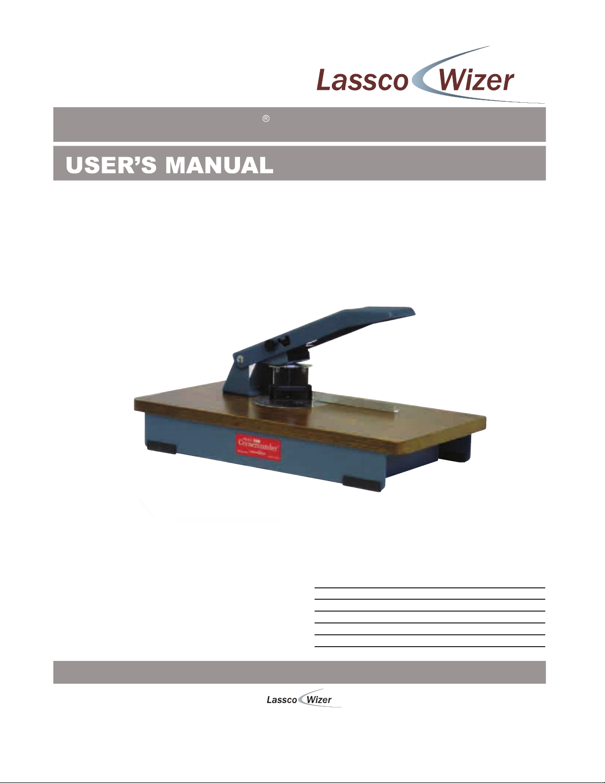
Slot #1
Slot #2
Slot #3
Handle Diagram