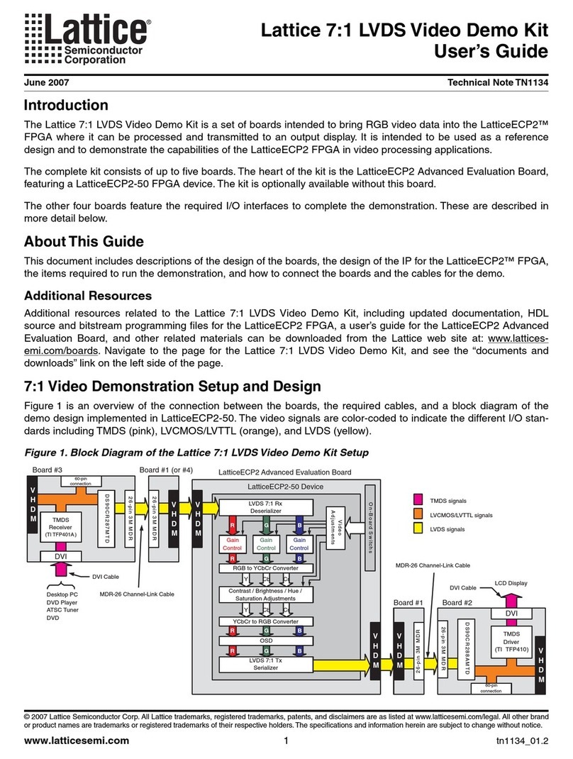
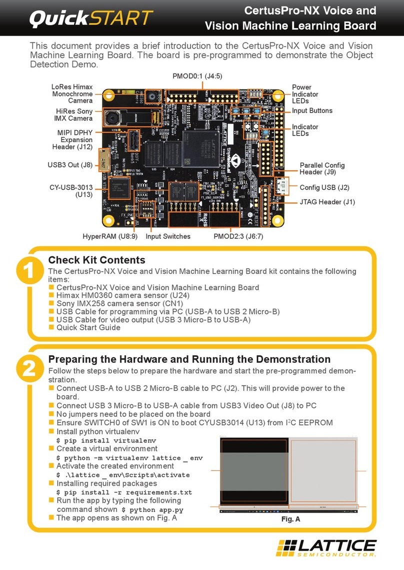
Lattice CrossLink-NX PCIe User manual

CrossLink-NX PCIe Bridge Board Basic Demo
User Guide
FPGA-UG-02145-1.0
December 2021

CrossLink-NX PCIe Bridge Board Basic Demo
User Guide
© 2021 Lattice Semiconductor Corp. All Lattice trademarks, registered trademarks, patents, and disclaimers are as listed at www.latticesemi.com/legal.
All other brand or product names are trademarks or registered trademarks of their respective holders. The specifications and information herein are subject to change without notice.
2 FPGA-UG-02145-1.0
Disclaimers
Lattice makes no warranty, representation, or guarantee regarding the accuracy of information contained in this document or the suitability of its
products for any particular purpose. All information herein is provided AS IS, with all faults and associated risk the responsibility entirely of the Buyer.
Buyer shall not rely on any data and performance specifications or parameters provided herein. Products sold by Lattice have been subject to limited
testing and it is the Buyer's responsibility to independently determine the suitability of any products and to test and verify the same. No Lattice
products should be used in conjunction with mission- or safety-critical or any other application in which the failure of Lattice’s product could create a
situation where personal injury, death, severe property or environmental damage may occur. The information provided in this document is
proprietary to Lattice Semiconductor, and Lattice reserves the right to make any changes to the information in this document or to any products at
any time without notice.

CrossLink-NX PCIe Bridge Board Basic Demo
User Guide
© 2021 Lattice Semiconductor Corp. All Lattice trademarks, registered trademarks, patents, and disclaimers are as listed at www.latticesemi.com/legal.
All other brand or product names are trademarks or registered trademarks of their respective holders. The specifications and information herein are subject to change without notice.
FPGA-UG-02145-1.0 3
Contents
Acronyms in This Document.................................................................................................................................................6
1. Introduction..................................................................................................................................................................7
1.1. Learning Objectives.............................................................................................................................................7
2. Hardware and Software Requirements........................................................................................................................8
2.1. Hardware Requirements.....................................................................................................................................8
2.2. Software Requirements ......................................................................................................................................8
3. Setting Up the Demo ....................................................................................................................................................9
3.1. Hardware Setup ..................................................................................................................................................9
3.1.1. Jumper Configuration.....................................................................................................................................9
3.1.2. Programming the FPGA................................................................................................................................10
3.1.3. Status LED.....................................................................................................................................................13
3.2. Software Setup..................................................................................................................................................14
3.2.1. Software Setup and Installation for Windows .............................................................................................14
3.2.2. Software Setup for Linux..............................................................................................................................27
4. Demo Design Overview ..............................................................................................................................................30
4.1. Theory of Operation..........................................................................................................................................30
4.2. FPGA Design......................................................................................................................................................31
4.2.1. PCIe Hard IP..................................................................................................................................................32
4.2.2. BAR RAM ......................................................................................................................................................32
4.2.3. Display Controller.........................................................................................................................................32
5. Application Overview .................................................................................................................................................33
5.1. Running the PCI Express Test Application.........................................................................................................33
5.2. Using the PCI Express Test Application User Interface .....................................................................................34
5.3. Running PCIe Basic Demo..................................................................................................................................35
5.4. Running PCIe Memory Access Demo ................................................................................................................37
6. Importing and Building the FPGA Demonstration......................................................................................................39
6.1. Hardware Directory Structure...........................................................................................................................39
6.2. Building Lattice Radiant Project ........................................................................................................................39
7. Troubleshooting .........................................................................................................................................................40
7.1. SPI Flash Update................................................................................................................................................40
7.2. Driver Installation and User Interface Launch for Windows.............................................................................41
7.2.1. Problem in Driver Installation ......................................................................................................................41
7.2.2. Problem with Launching User Interface.......................................................................................................41
7.3. Driver Installation User Interface Launch for Linux...........................................................................................42
7.3.1. Problem in Driver Loading............................................................................................................................42
7.3.2. Problem with User Interface Launching.......................................................................................................43
Technical Support Assistance .............................................................................................................................................44
Revision History..................................................................................................................................................................45

CrossLink-NX PCIe Bridge Board Basic Demo
User Guide
© 2021 Lattice Semiconductor Corp. All Lattice trademarks, registered trademarks, patents, and disclaimers are as listed at www.latticesemi.com/legal.
All other brand or product names are trademarks or registered trademarks of their respective holders. The specifications and information herein are subject to change without notice.
4 FPGA-UG-02145-1.0
Figures
Figure 3.1. CrossLink-NX PCIe Bridge Board Jumper Location..............................................................................................9
Figure 3.2. CrossLink-NX PCIe Bridge Board Connection....................................................................................................10
Figure 3.3. Creating a New Project from a Scan .................................................................................................................10
Figure 3.4. Radiant Programmer Window ..........................................................................................................................11
Figure 3.5. FPGA Device Settings ........................................................................................................................................11
Figure 3.6. Device Properties Window for SPI Flash Programming ....................................................................................12
Figure 3.7. Programmer Menu Bar.....................................................................................................................................12
Figure 3.8. Programmer Output Window...........................................................................................................................12
Figure 3.9. Status LED .........................................................................................................................................................13
Figure 3.10. Running Disable Integrity Checks Command..................................................................................................14
Figure 3.11. Running Test Sign On Command.....................................................................................................................14
Figure 3.12. Troubleshoot Option.......................................................................................................................................15
Figure 3.13. Advanced Options...........................................................................................................................................15
Figure 3.14. Select Startup Settings....................................................................................................................................16
Figure 3.15. Restarting Windows........................................................................................................................................16
Figure 3.16. Device Manager..............................................................................................................................................17
Figure 3.17. Showing Device Properties .............................................................................................................................17
Figure 3.18. Hardware IDs of Basic Demo Device...............................................................................................................18
Figure 3.19. Update Driver Menu in Device Manager........................................................................................................19
Figure 3.20. Update Driver Options....................................................................................................................................19
Figure 3.21. Browse the Driver for Device..........................................................................................................................20
Figure 3.22. Windows Security in Device Manager ............................................................................................................20
Figure 3.23. Driver Installation Status Message .................................................................................................................21
Figure 3.24. Basic Demo Device Name Displayed in Device Manager................................................................................21
Figure 3.25. Preparing to Install Page.................................................................................................................................22
Figure 3.26. Welcome Page ................................................................................................................................................22
Figure 3.27. Destination Folder Page..................................................................................................................................23
Figure 3.28. Summary Page ................................................................................................................................................23
Figure 3.29. Application Installed .......................................................................................................................................24
Figure 3.30. Device Configuration Prompt .........................................................................................................................24
Figure 3.31. Device Driver Installation Wizard ...................................................................................................................25
Figure 3.32. Windows Security in Driver Installation..........................................................................................................25
Figure 3.33. Device Driver Installation Completed .............................................................................................................26
Figure 4.1. Relationship of the Hardware and Software Components...............................................................................30
Figure 4.2. PCIe Basic Demo SW Design .............................................................................................................................31
Figure 4.3. PCIe Basic Demo FPGA Design ..........................................................................................................................31
Figure 5.1. PCIe Test Application Device Info Tab ..............................................................................................................33
Figure 5.2. PCIe Test Application Config Space Tab............................................................................................................34
Figure 5.3. Three 7-Segment Display on Board ..................................................................................................................35
Figure 5.4. Interactive 7 Segment Display Tab ...................................................................................................................35
Figure 5.5. PCIe Test Application Memory Tab...................................................................................................................37
Figure 7.1. TCK Frequency Setting......................................................................................................................................40
Figure 7.2. Port Selection....................................................................................................................................................40
Figure 7.3. User Interface with No Device Driver ...............................................................................................................41
Figure 7.4. Error Message...................................................................................................................................................42
Figure 7.5. lspci -vnm Output Image...................................................................................................................................42
Figure 7.6. Content List of Demonstration/Linux Directory. ..............................................................................................43
Figure 7.7. Content List of Software/Linux Directory .........................................................................................................43

CrossLink-NX PCIe Bridge Board Basic Demo
User Guide
© 2021 Lattice Semiconductor Corp. All Lattice trademarks, registered trademarks, patents, and disclaimers are as listed at www.latticesemi.com/legal.
All other brand or product names are trademarks or registered trademarks of their respective holders. The specifications and information herein are subject to change without notice.
FPGA-UG-02145-1.0 5
Tables
Table 3.1. Jumper Configuration ..........................................................................................................................................9
Table 3.2. Status LED Description.......................................................................................................................................13
Table 5.1. Device Info Tab ..................................................................................................................................................34
Table 5.2. Configuration Space Tab....................................................................................................................................34
Table 5.3. Memory Data and Corresponding 7 Segment Display Values ...........................................................................36
Table 5.4. Memory Tab.......................................................................................................................................................37

CrossLink-NX PCIe Bridge Board Basic Demo
User Guide
© 2021 Lattice Semiconductor Corp. All Lattice trademarks, registered trademarks, patents, and disclaimers are as listed at www.latticesemi.com/legal.
All other brand or product names are trademarks or registered trademarks of their respective holders. The specifications and information herein are subject to change without notice.
6 FPGA-UG-02145-1.0
Acronyms in This Document
A list of acronyms used in this document.
Acronym
Definition
BAR
Base Address Register
FDSOI
Fully Depleted Silicon on Insulator
FPGA
Field-Programmable Gate Array
LED
Light-emitting diode
MIPI
Mobile Industry Processor Interface
PCIe
PCI Express
PHY
Physical Layer
SPI
Serial Peripheral Interface
USB
Universal Serial Bus

CrossLink-NX PCIe Bridge Board Basic Demo
User Guide
© 2021 Lattice Semiconductor Corp. All Lattice trademarks, registered trademarks, patents, and disclaimers are as listed at www.latticesemi.com/legal.
All other brand or product names are trademarks or registered trademarks of their respective holders. The specifications and information herein are subject to change without notice.
FPGA-UG-02145-1.0 7
1. Introduction
This guide describes how to start using the CrossLink™-NX PCIe Bridge Board. The CrossLink-NX Bridge Board features
the CrossLink-NX FPGA in the 400-ball caBGA package (LIFCL-40-8BG400C), which is built on the Lattice Nexus FPGA
platform using low power 28 nm FDSOI technology. The board can expand the usability of the CrossLink-NX FPGA with
2.5 Gbps Hardened MIPI D-PHY, 5 Gbps PCIe, 1.5 Gbps programmable I/O, DDR3, USB 3.0, Ethernet, and SGMII. Board
resources such as jumpers, LED indicators, push buttons, and switches are available for user-defined applications.
This guide familiarizes you with the process of setting up your PCI Express development environment. It is assumed
that you do not have any associated tools installed on your system.
The demos discussed in this document include the PCI Express Basic Demo and PCI Express Memory Access Demo.
1.1. Learning Objectives
After completing the steps in this guide, you will be able to perform the following:
Set up the CrossLink-NX PCIe Bridge Board and become familiar with its main features
Install all applicable development tools and PCI Express demos
Establish communication between the CrossLink-NX PCIe Bridge Board through the PCI Express link
Run the PCI Express Basic Demo that allows you to control three 7 segment LEDs on the CrossLink-NX PCIe Bridge
Board. This demo is included in the user interface.
Run the PCI Express Memory Access Demo, which allows you to manipulate the onboard memory of the FPGA
through the PCIe slot. This demo is included in the user interface.
Use what the demo teaches you about designing Lattice PCI Express solutions.
Modify and rebuild the PCI Express Basic Demo.
Become familiar with the software development tools and major design flow steps employed in this kit.
Use other existing documentation in conjunction with this guide.
This document assumes that you have already installed the Lattice Radiant™ design software. This document covers
some of the basic of function of Lattice Radiant software. If you would like to learn more about Lattice Radiant
software, refer to the Lattice Radiant software Help system.

CrossLink-NX PCIe Bridge Board Basic Demo
User Guide
© 2021 Lattice Semiconductor Corp. All Lattice trademarks, registered trademarks, patents, and disclaimers are as listed at www.latticesemi.com/legal.
All other brand or product names are trademarks or registered trademarks of their respective holders. The specifications and information herein are subject to change without notice.
8 FPGA-UG-02145-1.0
2. Hardware and Software Requirements
2.1. Hardware Requirements
To install the kit design and run the demo software, a computer with a PCI Express ×16, ×8, ×4, or ×1 slot is required.
The computer must also have a USB port and be able to run the Lattice Radiant Software. All other hardware and
drivers are included in the kit.
Mini-USB to USB-A cable for programming the bitstream
12 V Power Adapter
CrossLink-NX PCIe Bridge Board
2.2. Software Requirements
The following software is required to obtain the expected results for the procedures described in this guide:
Lattice Radiant Software 2.2 or later (available at the Lattice website Design Software and IP page).
CrossLink-NX Basic Demo for Windows 10 or Linux
Windows 10 or Ubuntu 18.04.6
Bit file for the CrossLink-NX board SPI Flash (LIFCL-40_PCIe_Basic_Demo.bit)

CrossLink-NX PCIe Bridge Board Basic Demo
User Guide
© 2021 Lattice Semiconductor Corp. All Lattice trademarks, registered trademarks, patents, and disclaimers are as listed at www.latticesemi.com/legal.
All other brand or product names are trademarks or registered trademarks of their respective holders. The specifications and information herein are subject to change without notice.
FPGA-UG-02145-1.0 9
3. Setting Up the Demo
3.1. Hardware Setup
This section covers the steps in programming the demo to the SPI memory of the CrossLink-NX PCIe Bridge Board.
3.1.1. Jumper Configuration
Install the jumpers listed in Table 3.1. If this is the first time the board is used, the jumpers should be in the indicated
configuration.
Table 3.1. Jumper Configuration
Jumper Checklist
Configuration
J11, J18
Connect pins 1 and 2
J7, J6, J13, J14
Connect pins 1 and 2
J31, J32, J33
Connect pins 2 and 3
J8, J9, J10, J15, J16, J19, J20, J21, J22, J23, J25, J26, J29, J30,
J34, J35, J36, J37, J38, J39, J42
These are current measurement headers and should be kept
Open.
J51
Connect pins 2 and 4
J48
Connect pins 2 and 3
J27
Connect pins 1 and 2
J45, J46
Connect pins 1 and 2
J17
Open
Figure 3.1 shows the location of the jumpers.
J48
J51 Current
Measurement
2-Pin Header J31, J32, J33
J17
J27
J45, J46
J11, J18 J7, J6, J13, J14
Functional Jumper
Current Measurment Jumper
Figure 3.1. CrossLink-NX PCIe Bridge Board Jumper Location

CrossLink-NX PCIe Bridge Board Basic Demo
User Guide
© 2021 Lattice Semiconductor Corp. All Lattice trademarks, registered trademarks, patents, and disclaimers are as listed at www.latticesemi.com/legal.
All other brand or product names are trademarks or registered trademarks of their respective holders. The specifications and information herein are subject to change without notice.
10 FPGA-UG-02145-1.0
Make sure the card is plugged into a PCIe slot or connected to the 12 V input supply. If the card is plugged into the PCIe
slot, external power is provided by the system, and SW2 should be in the up position to receive power from the PCIe
slot. If external 12 V power is provided, then SW2 should be in the down position to receive power from the external
12 V connection. Connect the board to the PC running the Lattice Radiant software with the Mini USB Type A Cable as
shown in Figure 3.4.
Mini
USB
Type A
Cable 12 V Input
Supply
Connector
SW2
Figure 3.2. CrossLink-NX PCIe Bridge Board Connection
3.1.2. Programming the FPGA
To program the CrossLink-NX FPGA device:
1. Create a new project using the Lattice Radiant Programmer software. In the Getting Started dialog box, indicate
Project Name and Location as shown in Figure 3.3.
2. Select Create a new project from scan. Values are indicated in the Cable, Port, and TCK Divider Setting (0-30×)
fields.
3. Click OK.
Figure 3.3. Creating a New Project from a Scan

CrossLink-NX PCIe Bridge Board Basic Demo
User Guide
© 2021 Lattice Semiconductor Corp. All Lattice trademarks, registered trademarks, patents, and disclaimers are as listed at www.latticesemi.com/legal.
All other brand or product names are trademarks or registered trademarks of their respective holders. The specifications and information herein are subject to change without notice.
FPGA-UG-02145-1.0 11
4. The main interface opens as shown in Figure 3.4.
Figure 3.4. Radiant Programmer Window
5. If the Programmer settings do not match the settings shown in Figure 3.5, select these settings (Device Family and
others) manually from drop down menu.
Figure 3.5. FPGA Device Settings
To select programming settings:
1. Browse and select the Programming file LIFCL-40_PCIe_Basic_Demo.bit from CL-
NX_BridgeBoard_PCIe_BasicDemo\ Demonstration\Bitstream
2. Click OK.
3. Double-click under Operation to open the Device Properties dialog box.

CrossLink-NX PCIe Bridge Board Basic Demo
User Guide
© 2021 Lattice Semiconductor Corp. All Lattice trademarks, registered trademarks, patents, and disclaimers are as listed at www.latticesemi.com/legal.
All other brand or product names are trademarks or registered trademarks of their respective holders. The specifications and information herein are subject to change without notice.
12 FPGA-UG-02145-1.0
Figure 3.6. Device Properties Window for SPI Flash Programming
4. Select the settings as shown in Figure 3.6.
5. Click the Programming button from the menu bar shown in Figure 3.7 to start programming.
Figure 3.7. Programmer Menu Bar
When the FPGA programming is successful, the output console shows an Operation Successful message as shown in
Figure 3.8.
Figure 3.8. Programmer Output Window
If the programming operation was not successful, please refer to the troubleshooting section of this document.
After programming, power cycle the board and check the status LEDs on the board according to Table 3.2.

CrossLink-NX PCIe Bridge Board Basic Demo
User Guide
© 2021 Lattice Semiconductor Corp. All Lattice trademarks, registered trademarks, patents, and disclaimers are as listed at www.latticesemi.com/legal.
All other brand or product names are trademarks or registered trademarks of their respective holders. The specifications and information herein are subject to change without notice.
FPGA-UG-02145-1.0 13
3.1.3. Status LED
The three status LEDs are shown in Figure 3.9.
1 2 3
Figure 3.9. Status LED
The description of each status LED is provided in Table 3.2.
Table 3.2. Status LED Description
Sl. No
Name
Description
1
125MHz Clock present
Green Blinking when clock present
2
PCIe Link Up
Green: Lights up if PCIe link up is successful
Red: Lights up if PCIe link up is not successful
3
DONE
Green: Lights if configuration is successful

CrossLink-NX PCIe Bridge Board Basic Demo
User Guide
© 2021 Lattice Semiconductor Corp. All Lattice trademarks, registered trademarks, patents, and disclaimers are as listed at www.latticesemi.com/legal.
All other brand or product names are trademarks or registered trademarks of their respective holders. The specifications and information herein are subject to change without notice.
14 FPGA-UG-02145-1.0
3.2. Software Setup
This section provides the procedure for installing software onto the host machine.
3.2.1. Software Setup and Installation for Windows
Before installing the driver, driver signature enforcement should be disabled.
3.2.1.1. Disabling Driver Signature Enforcement Permanently
To permanently disable driver signature enforcement:
1. Start the Command Prompt as administrator.
2. Enter the following lines and press Enter.
bcdedit.exe -set loadoptions DISABLE_INTEGRITY_CHECKS
Figure 3.10. Running Disable Integrity Checks Command
bcdedit.exe -set TESTSIGNING ON
Figure 3.11. Running Test Sign On Command
3. Close the Command Prompt and restart your PC.

CrossLink-NX PCIe Bridge Board Basic Demo
User Guide
© 2021 Lattice Semiconductor Corp. All Lattice trademarks, registered trademarks, patents, and disclaimers are as listed at www.latticesemi.com/legal.
All other brand or product names are trademarks or registered trademarks of their respective holders. The specifications and information herein are subject to change without notice.
FPGA-UG-02145-1.0 15
3.2.1.2. Disabling Driver Signature Enforcement Temporarily
To disable the driver signature enforcement temporarily on Windows 10.
Note: if Driver Signature Enforcement is already disabled, skip this section and proceed to the Driver Installation
section.
1. Press the Windows key and click the power button.
2. Press and hold the Shift key and click Restart.
3. When the Choose an option screen appears as shown in Figure 3.12, release the Shift key.
4. Click Troubleshoot.
Figure 3.12. Troubleshoot Option
5. Select Advanced options and press Enter.
Figure 3.13. Advanced Options
6. Select Startup Settings and press Enter.

CrossLink-NX PCIe Bridge Board Basic Demo
User Guide
© 2021 Lattice Semiconductor Corp. All Lattice trademarks, registered trademarks, patents, and disclaimers are as listed at www.latticesemi.com/legal.
All other brand or product names are trademarks or registered trademarks of their respective holders. The specifications and information herein are subject to change without notice.
16 FPGA-UG-02145-1.0
Figure 3.14. Select Startup Settings
7. Press Enter to restart.
Figure 3.15. Restarting Windows
8. After restarting, select Option 7 to disable driver signature verification.
3.2.1.3. Driver Installation
There are two procedures to install the device driver:
Install manually
Install through user interface installer
Installing Basic Demo Device Driver Manually
The drivers for the Basic Demo can be found in the PCIeBasicDemo > Demonstration > Windows10 > Driver folder.
To install the Basic Demo device driver manually:
1. Open Device Manager, which shows the connected PCIe devices, as shown in Figure 3.16.
Note: If the Device Manager does not show the connected PCIe device, see the Troubleshooting section.

CrossLink-NX PCIe Bridge Board Basic Demo
User Guide
© 2021 Lattice Semiconductor Corp. All Lattice trademarks, registered trademarks, patents, and disclaimers are as listed at www.latticesemi.com/legal.
All other brand or product names are trademarks or registered trademarks of their respective holders. The specifications and information herein are subject to change without notice.
FPGA-UG-02145-1.0 17
Figure 3.16. Device Manager
2. Right-click the device and select Properties as shown in Figure 3.17.
Figure 3.17. Showing Device Properties
3. The information in Hardware IDs is needed to install the correct driver for the corresponding device. The Hardware
IDs of the Base System Device for the Basic Demo is PCI\VEN_1204&DEV_9C1D&SUBSYS_E00419AA as shown in
Figure 3.18.

CrossLink-NX PCIe Bridge Board Basic Demo
User Guide
© 2021 Lattice Semiconductor Corp. All Lattice trademarks, registered trademarks, patents, and disclaimers are as listed at www.latticesemi.com/legal.
All other brand or product names are trademarks or registered trademarks of their respective holders. The specifications and information herein are subject to change without notice.
18 FPGA-UG-02145-1.0
Figure 3.18. Hardware IDs of Basic Demo Device

CrossLink-NX PCIe Bridge Board Basic Demo
User Guide
© 2021 Lattice Semiconductor Corp. All Lattice trademarks, registered trademarks, patents, and disclaimers are as listed at www.latticesemi.com/legal.
All other brand or product names are trademarks or registered trademarks of their respective holders. The specifications and information herein are subject to change without notice.
FPGA-UG-02145-1.0 19
4. Right click on the device and select Update driver.
Figure 3.19. Update Driver Menu in Device Manager
5. Select the Browse my computer for driver software option as shown in Figure 3.20.
Figure 3.20. Update Driver Options

CrossLink-NX PCIe Bridge Board Basic Demo
User Guide
© 2021 Lattice Semiconductor Corp. All Lattice trademarks, registered trademarks, patents, and disclaimers are as listed at www.latticesemi.com/legal.
All other brand or product names are trademarks or registered trademarks of their respective holders. The specifications and information herein are subject to change without notice.
20 FPGA-UG-02145-1.0
6. Browse for the Basic Demo device driver as shown in Figure 3.21.
Figure 3.21. Browse the Driver for Device
7. If you receive a Windows Security prompt, select Install this driver software anyway as shown in Figure 3.22.
Figure 3.22. Windows Security in Device Manager
Table of contents
Other Lattice Computer Hardware manuals
Popular Computer Hardware manuals by other brands

ekwb
ekwb EK-Annihilator Pro ILM Series installation manual

AXIOMTEK
AXIOMTEK tBOX324-894 Quick installation guide

Mede8er
Mede8er MED10WF quick start guide

Phytec
Phytec phyCORE-MPC5676/57 Series Hardware manual

ADLINK Technology
ADLINK Technology aTCA-9300 user manual

Intel
Intel Xeon Phi Processor x200 Thermal/Mechanical Specification and Design Guide

Advantech
Advantech PCA-6277-B manual

Infineon
Infineon EVAL-XMC4800PSOC6M5 user guide

Atlantis
Atlantis NanoCOM-LN Quick installation guide

AGILTRON
AGILTRON NanoSpeed Operation manual

Supermicro
Supermicro SuperBlade SBA-4114S-C2N user manual

4gon
4gon RouterBOARD 433 Quick setup guide and warranty information