manuals.online logo
Brands
  1. Home
  2. •
  3. Brands
  4. •
  5. Launch
  6. •
  7. Control Unit
  8. •
  9. Launch X-431 PADII User manual

Launch X-431 PADII User manual

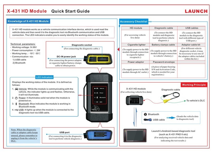
X-431 HD Module ( )Android-based User Manual LAUNCH
了解 诊 断盒
2
Download and Install X-431 HD Module App
1. Visit the LAUNCH website and download the application corresponding to
the X-431 HD module;
Note: If downloading using the diagnostic tool, please be sure that Wi-Fi has
good or strong signals. For details on Wi-Fi connection, refer to the user’s
manual of the diagnostic tool.
2. Follow the on-screen instructions to install it. Once installation is
complete, an application icon will appear on the HOME screen.
X-431 HD Module
Technical
Parameters
Working Voltage: 8~24V Working Temperature: -15℃~60℃
Storage Temperature: -20℃~70℃ Relative Temperature: 10% ~80%
1
Vehicle Connections
1. Locate the DLC (Data Link Connector) of the truck. It is generally located
in driver’s cab. In case no DLC is found, please refer to the Repair
Handbook of trucks.
2. Plug one end of the diagnostic main cable into DB15 connector and the
other end into the truck’s DLC. Normally the power indicator of X-431 HD
module will light up.
For trucks with non-16 pin DLC, please choose the corresponding
diagnostic connector.
X-431 HD Module
To Truck’s
DLC
Main Cable
Communication Port of – To connect to COM port of the PC.
(Note: This port is currently disabled and reserved for future use.)
PC
Indicators
B-shaped Port – To connect to the B-shaped terminal of USB cable.
(Note: This port is currently disabled and reserved for future use.)
The indicators are defined as follows (from left to right):
(Only reserved for
future use)
Power Indicator: It lights up when it is powered on.


Communication Indicator of Diagnostic Tool: It illuminates when X-431 HD module is communicating with
the diagnostic tool.
Communication Indicator of Vehicle: It lights up once X-431 HD module is connected to a truck’s DLC.
Communication Indicator of PC: It lights up if X-431 HD module is connected to the COM port of a PC (Only
reserved for future use).
USB Status Indicator: It illuminates when the USB cable is plugged into X-431 HD module
.
Bluetooth Indicator: It lights up if X-431 HD module is communicating with the vehicle’s DLC.
Diagnostic Port – To connect to diagnostic main cable.
Power Jack – To connect the included power adaptor.
X-431 HD Module
For accessing vehicle data( )
Main Cable
Bluetooth (Sending vehicle data to a diagnostic tool)
Android-based Diagnostic Tool
data and displaying test results.)
(For analyzing collected vehicle
To Vehicle’s
DLC
5 3
How to Diagnose a Vehicle
Activate X-431 HD Module
Tap “Diagnostic”
Select truck make
Select test systemSelect test function
Tap “Login”
Activate X-431
HD module?
No
Tap “Update” to
download or update
software
Yes
Follow instructions to
activate X-431 HD
module
4
Bluetooth Settings
Before diagnosing a vehicle, you are suggested to make a Bluetooth pair between X-431 HD
module and the diagnostic tool. Proceed as follows:
1. Enter Bluetooth setting screen (“Settings” --> “Bluetooth”), slide the Bluetooth switch to
ON and will start searching all available Bluetooth devices.
2. Tap the desired one, then key in the PIN code (the default value is 0000) in the pop-up
dialog box, and then tap “Pair”.
By default, the Bluetooth name is 98454*****00 (where ***** stands for 5 digits.).
3. Once it is paired successfully, it will appear in the paired devices list.
Note: If no Bluetooth setting is done before diagnostic application is launched, you can also
configure it while using the software.
Follow the steps described below to activate X-431 HD module:
Note: Please make sure that your diagnostic tool is properly connected to the internet before proceed
this step.
1. Launch the application you just installed, then tap -- > “Profile” to enter, and then tap
“Connector Activation”to go into a screen similar to the following:
2. Input the Product S/N and Verification Code (can be obtained from the included
Password Envelope) , then tap “Activate” to activate the X-431 HD module.
Vehicle Diagnosis Principle
Note: Diagnosing a car features same
operations as diagnosing a truck. For
details on how to diagnose a truck,
please refer to user manual included
with the diagnostic tool.
Product S/N
Verification Code
LAUNCH
Password Envelope
X-431 PRO3 X-431 PADII
X-431 HD Module ( )Android-based User Manual
Vehicle Diagnosis Flowchart
文档大小:原始文档为A4纸张(宽297mm x 高210mm),按照1:1输出
材质要求:157G双铜
印刷要求:彩色印刷

Other manuals for X-431 PADII

10

This manual suits for next models

2

Other Launch Control Unit manuals

Launch X-431 PADII User manual

Launch

Launch X-431 PADII User manual

Launch X-431 HD User manual

Launch

Launch X-431 HD User manual

Popular Control Unit manuals by other brands

Kohler TOUCHLESS K-13686 installation instructions

Kohler

Kohler TOUCHLESS K-13686 installation instructions

Belden Lumberg Automation Lumberg Automation 0980 ESL 811-EIP... Technical manual

Belden

Belden Lumberg Automation Lumberg Automation 0980 ESL 811-EIP... Technical manual

M-system R3-NF1 instruction manual

M-system

M-system R3-NF1 instruction manual

Xylem McDonnell & Miller RB-24E instruction manual

Xylem

Xylem McDonnell & Miller RB-24E instruction manual

GAPOSA QCzero2 instructions

GAPOSA

GAPOSA QCzero2 instructions

b&t XW-01 manual

b&t

b&t XW-01 manual

Festo ZSB-1/8-B Original instructions

Festo

Festo ZSB-1/8-B Original instructions

Victaulic 751 FireLock Series Installation, Maintenance, & Testing Manual

Victaulic

Victaulic 751 FireLock Series Installation, Maintenance, & Testing Manual

3Com 2103R-CSDI installation guide

3Com

3Com 2103R-CSDI installation guide

Vimar SL24.W Installer quick guide

Vimar

Vimar SL24.W Installer quick guide

ClimateMaster Flow Controller 3 Installation, operation & maintenance instructions

ClimateMaster

ClimateMaster Flow Controller 3 Installation, operation & maintenance instructions

Mallory FIRE STORM 69050S Hardware installation

Mallory

Mallory FIRE STORM 69050S Hardware installation

Vag GA INDUSTRIES Figure 922 Installation, operation and maintenance manual

Vag

Vag GA INDUSTRIES Figure 922 Installation, operation and maintenance manual

Dea 400RR Operating instructions and warnings

Dea

Dea 400RR Operating instructions and warnings

HBX SNO-0550 installation manual

HBX

HBX SNO-0550 installation manual

ASG X-PAQ ASG-NW2500-EIP user guide

ASG

ASG X-PAQ ASG-NW2500-EIP user guide

ABB FPNO-21 Quick installation and start-up guide

ABB

ABB FPNO-21 Quick installation and start-up guide

Graco 256556 Instructions-parts list

Graco

Graco 256556 Instructions-parts list

manuals.online logo
manuals.online logoBrands
  • About & Mission
  • Contact us
  • Privacy Policy
  • Terms and Conditions

Copyright 2025 Manuals.Online. All Rights Reserved.