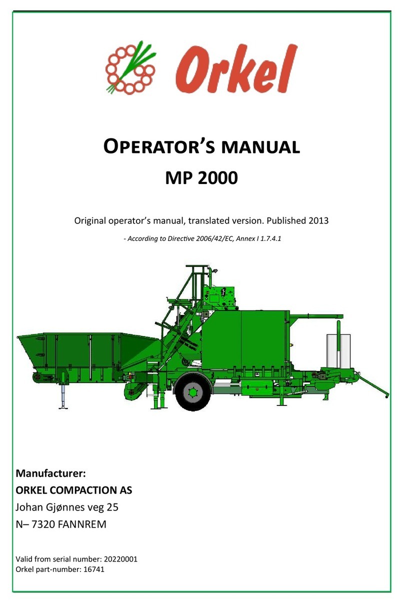
Laverda M300 User manual

Operator's Manual
Combines
M300 - M310
Breganze
AGCO S.p.A. - Via F. Laverda, 15/17 - 36042
BREGANZE (VI) – Italy.
LAVERDA® is a European brand of AGCO
© AGCO 2016
Original Operator's Manual
November 2016
M300-M310_EN_327305015
EAME
English

Combines
1 General Information .......................................................15
1.1 Information ........................................................17
1.1.1 Introduction .....................................................17
1.1.2 Company policy ..................................................17
1.1.3 Optional equipment ...............................................17
1.1.4 Spare parts and accessories .........................................18
1.1.5 Warranty .......................................................18
1.1.6 Lubricants ......................................................18
1.2 Use ................................................................20
1.2.1 Use of the combine ...............................................20
1.3 Identification .......................................................21
1.3.1 Combine identification .............................................21
1.3.2 Engine Identification ...............................................22
1.3.3 Cutting table identification ..........................................23
1.3.4 Operator seat identification ..........................................23
1.3.5 Hydrostatic pump identification .......................................24
1.3.6 Hydrostatic motor identification .......................................24
1.3.7 Straw chopper identification (if fitted) ..................................25
1.3.8 Chaff spreader identification (if fitted) ..................................25
1.3.9 Trailer hitch identification (if fitted) .....................................26
1.4 Identification form ..................................................27
1.4.1 Machine data ....................................................27
1.5 Conformity .........................................................28
1.5.1 EC Declaration of Conformity ........................................28
1.6 Information ........................................................29
1.6.1 Ecology .......................................................29
1.6.2 Hydraulic systems: hoses ..........................................29
1.6.3 Scrapping and disposal ............................................30
1.7 Weight .............................................................31
1.7.1 Weight distribution ................................................31
2 Safety ....................................................................33
2.1 Warning symbols and safety instructions ............................35
2.1.1 Warnings ......................................................35
2.2 Information for road transport .......................................36
2.2.1 Road transport ..................................................36
2.3 Information for operations ..........................................39
2.3.1 Field Operations .................................................39
2.4 Information for maintenance ........................................43
2.4.1 Maintenance work ...............................................43
2.5 Information on the engine ...........................................47
2.5.1 Engine .........................................................47
2.6 Safety and function decals ..........................................51
2.6.1 Location of decals ................................................51
2.6.2 Description of decals ..............................................54
2.7 Work on the battery ................................................66
2.7.1 Battery ........................................................66
2.8 Safety devices ......................................................67
2.8.1 Emergency exit ..................................................67
Table of contents
Combines
M300-M310_EN_327305015
Find manuals at https://best-manuals.com

2.8.2 Operator presence device ...........................................68
2.8.2.1 Returning the machine to normal operation ........................68
2.8.2.2 Operator presence device anomaly ..............................69
2.8.3 Safety belts .....................................................70
2.8.4 Cutting table safety stops ...........................................71
2.8.5 Safety guard for main crop elevator ....................................72
2.8.6 Sprags for wheels ................................................72
2.8.7 Audible alarm for reversing ..........................................73
2.8.8 Reflectors for road transport .........................................74
2.8.9 Safety Guards ...................................................75
2.8.10 Fall protection rails ...............................................75
2.8.11 Safety devices for operations to be carried out in the upper part of the machine ..77
2.8.12 Straw Chopper (if fitted) ...........................................78
2.8.13 Fire extinguisher .................................................78
2.9 Trailer hitch ........................................................79
2.9.1 Automatic towing hooks ............................................79
2.9.2 CUNA and CE trailer hitches .........................................80
2.9.2.1 Procedure for attaching and removing ...........................81
2.9.2.2 Drawbar coupling ..........................................82
2.9.3 ROCKINGER trailer hitch ............................................82
2.9.3.1 Removal .................................................82
2.9.3.2 Drawbar coupling ..........................................83
2.9.4 Fixed trailer hitch (non-automatic - CUNA type) ...........................84
2.10 Machine lifting ....................................................85
2.10.1 Attachment points ...............................................85
2.11 Towing ...........................................................86
2.11.1 Towing the combine ..............................................86
2.12 Further information ................................................87
2.12.1 Noise level in the cab .............................................87
2.12.2 Vibrations in the cab .............................................87
2.12.3 Statutory regulations .............................................87
2.12.4 Electromagnetic emissions ........................................88
2.13 Notes .............................................................89
2.13.1 Notes for road transport ...........................................89
3 Operation .................................................................91
3.1 Combine operation .................................................93
3.1.1 Crop processing .................................................93
3.2 Stage 1 ............................................................94
3.2.1 Feeding ........................................................94
3.3 Stage 2 ............................................................95
3.3.1 Threshing ......................................................95
3.4 Stage 3 ............................................................96
3.4.1 Separation ......................................................96
3.5 Stage 4 ............................................................97
3.5.1 Cleaning .......................................................97
3.6 Stage 5 ............................................................98
3.6.1 Grain storage and unloading .........................................98
3.7 Transmission .......................................................99
3.7.1 Rear-wheel drive (4WD) ............................................99
4 Controls and Instruments .................................................101
4.1 Steering column ...................................................103
4.1.1 Adjustments ................................................... 103
4.1.2 Ignition switch. ..................................................104
Table of contents
Combines
M300-M310_EN_327305015
Find manuals at https://best-manuals.com

4.1.3 Direction indicators ...............................................105
4.2 Brakes ............................................................ 106
4.2.1 Brake pedals ................................................... 106
4.2.2 Service brakes .................................................. 106
4.2.3 Park brake ..................................................... 107
4.3 Multifunction lever ................................................ 108
4.3.1 Main components ............................................... 108
4.3.2 Push buttons on the multifunction lever ................................109
4.4 Gear shift lever and reversing lever ................................. 111
4.4.1 General Information .............................................. 111
4.5 Instrument panel .................................................. 112
4.5.1 Components ................................................... 112
4.5.2 Armrest .......................................................113
4.5.3 Throttle control ..................................................113
4.5.4 Switch for threshing mechanism and straw chopper ...................... 114
4.5.5 Switch for feed mechanism engagement ...............................114
4.5.6 Switch for four-wheel drive (optional) ..................................115
4.5.7 Miscellaneous push buttons ........................................ 115
4.5.8 Push button for road transport mode ..................................116
4.6 Computer ......................................................... 117
4.6.1 Description .................................................... 117
4.6.1.1 Screen ................................................. 118
4.6.1.2 Push buttons and knob ..................................... 121
4.6.2 Main function controls ............................................ 122
4.6.2.1 Activated device checks .....................................125
4.6.2.2 Meaning of the symbols: .................................... 125
4.6.3 Combine main menu ............................................. 126
4.6.3.1 Cells (4 and 5) of the Combine main menu ....................... 127
4.6.4 Machine settings and performance control ............................. 128
4.6.5 Setting straw chopper deflectors .....................................129
4.6.6 Monitoring performance and returns ..................................130
4.6.7 Header settings ................................................. 131
4.6.7.1 Header configuration ....................................... 132
4.6.7.2 Advanced header settings ................................... 133
4.6.7.3 Header settings ...........................................134
4.6.8 Reel ......................................................... 136
4.6.9 Automatic controls ...............................................137
4.6.10 Preset height .................................................. 138
4.6.11 Automatic height ............................................... 139
4.6.12 Field pressure ................................................. 141
4.6.13 Lateral floatation ................................................142
4.6.14 Automatic control combinations .................................... 142
4.6.14.1 Pre-set height and Automatic height ...........................143
4.6.14.2 Pre-set height and Field pressure ............................. 145
4.6.14.3 Pre-set height and Lateral flotation ............................ 145
4.6.14.4 Pre-set height, Automatic height and Field pressure ............... 146
4.6.14.5 Pre-set height, Automatic height and Lateral flotation .............. 148
4.6.14.6 Pre-set height, Field pressure and Lateral floatation ................148
4.6.14.7 Pre-set height, Automatic height, Field pressure and Lateral floatation
(recommended setting) ........................................... 149
4.6.14.8 Automatic height and Field pressure ...........................150
4.6.14.9 Automatic height and Lateral flotation ..........................152
4.6.14.10 Automatic height, Field pressure and Lateral floatation .............152
4.6.14.11 Field pressure and Lateral floatation .......................... 153
4.6.15 Settings for harvesting specific crops ................................ 154
4.6.16 Shafts and engine ...............................................155
4.6.17 Maintenance & calibration .........................................156
Table of contents
Combines
M300-M310_EN_327305015
Find manuals at https://best-manuals.com

4.6.17.1 Calibrations .............................................157
4.6.17.2 Information on the management system ....................... 158
4.6.17.3 System setup ...........................................159
4.6.18 Error codes ................................................... 162
4.6.19 Diagnostics ................................................... 164
4.6.20 Meters .......................................................167
4.6.21 Display adjustment ..............................................168
4.6.21.1 Night-time screen brightness ................................ 169
4.6.21.2 Screen calibration ........................................ 170
4.6.21.3 Cleaning the screen .......................................171
4.7 Cab ...............................................................172
4.7.1 Main components ............................................... 172
4.7.2 Air conditioning ................................................. 173
4.7.2.1 Compressor ............................................. 173
4.7.2.2 Condenser .............................................. 174
4.7.2.3 Expansion valve – evaporator .................................174
4.7.3 Pressurization and heating ......................................... 175
4.7.4 Cab controls ....................................................177
4.7.4.1 Rear-view mirrors .........................................181
4.7.5 Cab seats ......................................................182
4.7.6 Other cab components ............................................184
4.7.6.1 Refrigerator ..............................................184
4.7.6.2 Document Pocket ......................................... 184
4.7.6.3 Sun visor ................................................185
4.7.6.4 Rear Cab Window ......................................... 186
4.7.6.5 Reading light .............................................186
4.7.6.6 Footrest ................................................ 187
4.7.6.7 Preparation for radio installation ............................... 187
4.8 Access to combine components .................................... 188
4.8.1 Access to the operator platform ..................................... 188
4.8.2 Access to and cleaning of the front windshield of the cab ...................189
4.8.3 Cleaning the rear-view mirrors .......................................190
4.8.4 Cleaning the camera ..............................................191
4.8.5 Access to the engine compartment ...................................191
4.8.6 Access to the grain tank ...........................................192
4.8.7 Access to the inside of the grain tank ................................. 193
4.9 Engine ............................................................ 194
4.9.1 Starting the engine ...............................................194
4.9.2 Useful advice ...................................................195
4.9.3 Stopping the engine ..............................................196
4.10 Road transport ................................................... 197
4.10.1 Operations to be carried out before transportation ....................... 197
4.11 Using the combine ............................................... 200
4.11.1 Operations to be carried out before use ...............................200
5 Field Operations ..........................................................201
5.1 General Information ............................................... 203
5.1.1 Notes ........................................................ 203
5.1.2 Before operating the machine in the field ...............................203
5.2 Starting and Stopping the Combine .................................205
5.2.1 Procedure to follow .............................................. 205
5.3 Cutting table ...................................................... 207
5.3.1 Attaching and removing the table .................................... 207
5.3.2 Table lateral floatation .............................................211
5.4 Main Crop Elevator ................................................ 212
5.4.1 Adjustments ................................................... 212
Table of contents
Combines
M300-M310_EN_327305015
Find manuals at https://best-manuals.com

5.4.1.1 Access to the main components .............................. 214
5.4.1.2 P.F.R. — Finger feed roller ...................................215
5.4.2 Reverse drive system .............................................216
5.4.3 Stone trap ..................................................... 217
5.4.3.1 Stone trap assembly removal/refitting ...........................218
5.5 Cylinder Housing .................................................. 220
5.5.1 Threshing drum ................................................. 220
5.5.1.1 Unblocking the cylinder ..................................... 221
5.5.2 Concave ...................................................... 222
5.5.2.1 Concave filler plates (wheat concave) ...........................223
5.5.2.2 Parallelism between the cylinder and concave .....................224
5.5.3 Sectional concave ............................................... 225
5.5.3.1 Concave filler plates ........................................226
5.5.3.2 Parallelism between the cylinder and concave .....................227
5.5.4 Universal wheat/maize concave ..................................... 228
5.5.4.1 Basic settings - universal concave ..............................229
5.5.5 Spike-toothed Cylinder/Concave (for rice) ...............................230
5.5.6 Rear beater .................................................... 232
5.6 Multi-Crop Separator (MCS) ........................................233
5.6.1 Operational description ............................................233
5.6.2 Checking the concave position ...................................... 234
5.6.3 Disengaging the Multi Crop Separator concaves ..........................235
5.6.4 Multi Crop Separator speed ........................................ 236
5.7 Straw walkers .....................................................238
5.7.1 Description and adjustments ........................................238
5.8 Main Grain Pan ....................................................240
5.8.1 Description .................................................... 240
5.8.2 Checking the main grain pan ........................................241
5.8.3 Cleaning the main grain pan ........................................ 243
5.9 Fanning Mill .......................................................244
5.9.1 Description and adjustments ........................................244
5.9.1.1 Fanning mill for threshing light seed crops ....................... 246
5.10 Top sieve ........................................................ 247
5.10.1 Adjustment ................................................... 247
5.11 Bottom sieve .....................................................251
5.11.1 Adjustment ................................................... 251
5.12 Tailings .......................................................... 253
5.12.1 Description and adjustments .......................................253
5.13 Grain tank ....................................................... 255
5.13.1 Description ................................................... 255
5.13.1.1 Grain tank unloading auger ..................................255
5.13.1.2 Sensors to check tank filling .................................256
5.13.1.3 Grain tank control window .................................. 257
5.13.1.4 Doors for Grain Tank Maintenance and Cleaning .................. 258
5.13.1.5 Vertical auger tank drain door ................................259
5.13.1.6 Tank bottom door ........................................ 259
5.13.1.7 Grain Tank Cover .........................................260
5.13.2 Basic Settings ................................................. 262
6 Lubrication and Maintenance ............................................. 265
6.1 General Information ............................................... 267
6.1.1 Lubrication and Maintenance ....................................... 267
6.2 Preliminary Service Inspection ......................................269
6.2.1 After the first 50 working hours ......................................269
6.3 Scheduled Service Inspection .......................................270
6.3.1 Operation and adjustment ..........................................270
Table of contents
Combines
M300-M310_EN_327305015
Find manuals at https://best-manuals.com

6.3.2 When and where to carry it out ......................................271
6.3.3 Interval - 10 hours ............................................... 276
6.3.3.1 Hydraulic and hydrostatic systems tank (1) ....................... 276
6.3.3.2 Engine oil (2) .............................................277
6.3.3.3 Threshing drum variator (3) ...................................278
6.3.3.4 Coolant expansion tank (4) ...................................278
6.3.3.5 Prefilter/water separator (5) .................................. 279
6.3.3.6 Straw chopper rotor (6) ..................................... 279
6.3.4 Interval - 50 hours ............................................... 280
6.3.4.1 Rear axle support (11) ...................................... 280
6.3.4.2 Table drive-belt tensioner (12) ................................ 280
6.3.4.3 Service brakes (13) ........................................ 281
6.3.4.4 Cab air filters (14) ......................................... 281
6.3.4.5 Fanning mill variator (15) .................................... 283
6.3.4.6 Coupling bushes of final drive shafts (16) ........................ 283
6.3.4.7 Rear-axle king pins (17) ..................................... 284
6.3.4.8 Evaporator (18) ........................................... 284
6.3.4.9 Condenser (19) ........................................... 285
6.3.4.10 Engine radiator and hydraulic oil radiator (20) .....................286
6.3.4.11 Adjusting the rotary screen brushes and aspirator brushes ...........287
6.3.4.12 Grain-tank filling auger gearbox (21) ........................... 288
6.3.4.13 Track frames (22) .........................................289
6.3.4.14 Rear straw walker shaft supports (23) ......................... 290
6.3.5 Interval - 100 hours ...............................................291
6.3.5.1 Unloading auger bottom gearbox (31) ...........................291
6.3.5.2 Crop-unloading auger drive belt tensioner (32) .....................292
6.3.5.3 Main crop-elevator belt tensioner (33) ...........................292
6.3.5.4 Chaff spreader drive (if installed) (34) ........................... 293
6.3.5.5 Crop unloading-auger control cylinder (35) ........................293
6.3.5.6 Main crop elevator adapter (36) ............................... 294
6.3.5.7 MCS belt tensioner (if installed) (37) ........................... 294
6.3.5.8 Threshing-mechanism belt tensioner (38) ........................ 295
6.3.5.9 Hydrostatic-pump belt tensioner (39) ...........................295
6.3.5.10 Cab access ladder (40) .................................... 296
6.3.5.11 Tires (41) ...............................................296
6.3.5.12 Main crop elevator supports (42) ..............................297
6.3.5.13 Rear wheel 4WD tie rod (if fitted) (43) ..........................298
6.3.5.14 Engine (44) ............................................. 298
6.3.5.15 Engine air filter (45) ....................................... 299
6.3.5.16 Park brake (46) .......................................... 300
6.3.6 Interval - 250 hours ...............................................301
6.3.6.1 Gearbox (61) ............................................. 301
6.3.6.2 Reduction gearbox (62) ..................................... 301
6.3.6.3 Main clutch (63) ...........................................302
6.3.6.4 Unloading auger support (64) ................................. 302
6.3.6.5 Straw chopper driven-belt tensioner (65) .........................303
6.3.6.6 Straw chopper drive-belt tensioner (66) ..........................303
6.3.6.7 Straw chopper idler shaft (67) .................................304
6.3.6.8 Tank unloading-auger clutch (68) ...............................304
6.3.6.9 Aspirator drive-belt tensioner (69) ..............................305
6.3.6.10 Rotary-screen belt tensioner (70) .............................305
6.3.6.11 Windshield wash fluid reservoir (71) ........................... 306
6.3.6.12 Engine oil and filters (72) ................................... 306
6.3.6.13 Tailing-auger left support (73) ............................... 309
6.3.6.14 Unloading-auger top angle gear (74) ........................... 309
6.3.7 Interval - 500 hours ...............................................310
6.3.7.1 Hydraulic systems oil (81) ................................... 310
6.3.7.2 Hydraulic and hydrostatic systems return filter (82) ................. 311
Table of contents
Combines
M300-M310_EN_327305015
Find manuals at https://best-manuals.com

6.3.7.3 Hydraulic-oil intake filter (83) ..................................312
6.3.7.4 Hydrostatic transmission filter (84) ............................. 312
6.3.7.5 Engine diesel-fuel filters (85) ................................. 313
6.3.7.6 Dehydrator filter (86) ....................................... 314
6.3.7.7 Catalytic fluid filter (87) ..................................... 315
6.3.7.8 Reduction gears (88) ....................................... 316
6.3.7.9 Gearbox (89) ............................................. 316
6.3.7.10 Air compressor (if installed) (90) .............................. 317
6.3.7.11 Battery (91) .............................................317
6.4 Periodical maintenance operations ..................................318
6.4.1 Description .................................................... 318
6.4.1.1 Engine valves (1) ..........................................319
6.4.1.2 Coolant (2) .............................................. 320
6.4.1.3 Service brake circuit fluid (3) ..................................321
6.4.1.4 Diesel fuel tank (4) .........................................321
6.4.1.5 Turbocharger (5) .......................................... 322
6.4.1.6 Hydraulic hoses (6) ........................................ 322
6.4.1.7 Catalytic fluid tank (DEF) (7) .................................. 323
6.5 Lubrication ........................................................324
6.5.1 Summary table ..................................................324
7 Adjustments ............................................................. 325
7.1 Adjustments ...................................................... 327
7.1.1 Important information ............................................ 327
7.2 Belt and chain adjustment ..........................................328
7.2.1 Belts and chains (left-hand side) ..................................... 328
7.2.1.1 Feeder drive belt (1) ........................................329
7.2.1.2 Threshing unit drive belt (2) .................................. 330
7.2.1.3 Multi-Crop Separator drive belt (3) ............................. 331
7.2.1.4 Unloading-auger drive belt (4) .................................332
7.2.1.5 Belt drive for hydrostatic pump (5) ............................. 333
7.2.1.6 Belt drive for chaff spreader (if fitted) (6) .........................334
7.2.1.7 Belt drive for reversing (7) ................................... 335
7.2.1.8 Main transmission belt (8) ................................... 336
7.2.1.9 Belt drives for good grain and tailings augers (9) ................... 337
7.2.1.10 Belt drive for straw walkers (10) ..............................337
7.2.1.11 Belt drive for cutting table (11) ............................... 338
7.2.1.12 Chain drive for unloading auger (12) ........................... 338
7.2.1.13 Belt drive for straw chopper (if fitted) (13) .......................339
7.2.1.14 Belt drive for straw chopper (if fitted) (14) .......................340
7.2.1.15 Air-compressor drive belt (if installed) (15) .......................341
7.2.2 Belts and chains (right-hand side) .................................... 343
7.2.2.1 Reel-pump drive belt (20) ....................................344
7.2.2.2 Dust aspirator drive belt (21) ..................................344
7.2.2.3 Rotary-screen drive belt (22) ..................................345
7.2.2.4 Belt drive for engine coolant pump (23) ..........................345
7.2.2.5 Drive belt for engine fan and alternator (24) .......................346
7.2.2.6 Belt drive for cylinder variator (25) ..............................346
7.2.2.7 Belt drive for fanning mill variator (26) ...........................347
7.2.2.8 Top chain drive for tailings auger (27) ........................... 348
7.2.2.9 Crop elevator chain (28) .....................................348
7.2.2.10 Chain drive for tailings elevator (29) ........................... 349
7.2.2.11 Front crop elevator chain (30) ................................349
7.2.2.12 Finger-feed-roller drive chain (31) ............................. 350
7.2.2.13 Tank filling-auger drive chain (32) ............................. 350
7.2.2.14 Belt drive for cab air conditioning compressor (33) .................351
7.3 Reverse drive system .............................................. 352
Table of contents
Combines
M300-M310_EN_327305015
Find manuals at https://best-manuals.com

7.3.1 Adjustment of control tie rod ........................................352
7.3.2 Adjustment of the distance between disks ............................. 353
7.4 Slip clutches ...................................................... 354
7.4.1 Description .................................................... 354
7.4.1.1 Clutch for main crop elevator upper shaft (1) ......................354
7.4.1.2 Clutch on finger feed roller (2) ................................ 354
7.4.1.3 Clutch for shaker shoe counter drive (3) ......................... 355
7.4.1.4 Shear bolt for unloading-auger counter drive (4) ....................355
7.5 Grain tank unloading auger ........................................ 356
7.5.1 Adjustment of the support ......................................... 356
7.6 Tires ..............................................................357
7.6.1 Tire pressure ................................................... 357
7.6.2 Replacement of Front Wheels .......................................358
7.6.3 Replacement of Rear Wheels ....................................... 359
7.6.4 Front and rear wheels assembly ..................................... 360
7.7 Brakes ............................................................ 361
7.7.1 Service brakes .................................................. 361
7.7.2 Park brake ..................................................... 362
7.8 Rear axle ..........................................................363
7.8.1 Toe-in setting ...................................................363
7.8.2 Steering ram ball joints ............................................363
7.8.3 Width setting ...................................................364
7.8.4 Telescopic arm position ........................................... 365
7.8.5 Rear axle support ................................................367
7.9 Battery ............................................................368
7.9.1 Battery Replacement ............................................. 368
7.9.2 Suggestions regarding the battery ....................................369
8 Systems ................................................................. 371
8.1 Safety Precautions .................................................373
8.1.1 Notes ........................................................ 373
8.2 Engine supply system ..............................................374
8.2.1 Permitted fuels ................................................. 374
8.2.2 Fuel Circuit .................................................... 375
8.2.3 Bleeding the Fuel Supply Circuit ..................................... 376
8.2.4 Catalytic fluid tank (DEF) ...........................................377
8.2.5 Injection system operation ......................................... 378
8.3 Engine air intake and exhaust system ...............................380
8.3.1 Operation ......................................................380
8.4 Engine cooling system ............................................. 382
8.4.1 Coolant ....................................................... 382
8.4.2 Engine cooling system operation .....................................383
8.5 Engine lubrication system ..........................................384
8.5.1 Operation ......................................................384
8.5.2 Oil vapor recovery system ......................................... 385
8.6 SCR system ....................................................... 386
8.6.1 Operation ......................................................386
8.7 Hydraulics system ................................................. 389
8.7.1 Pumps and fuel tank ..............................................389
8.7.2 Table positioning hydraulic circuits ....................................391
8.7.2.1 Cutting table oleopneumatic shock absorbers ..................... 392
8.7.2.2 Flow rate proportional valve .................................. 392
8.7.2.3 Hose burst valves ......................................... 393
8.7.2.4 Table horizontal positioning circuit ............................. 393
8.7.3 Reel rotation control hydraulic circuit ..................................394
Table of contents
Combines
M300-M310_EN_327305015
Find manuals at https://best-manuals.com

8.7.4 Hydraulic steering system ..........................................395
8.7.5 Auxiliary hydraulics circuit ..........................................396
8.8 Hydrostatic transmission system ................................... 397
8.8.1 Front-wheel drive ................................................397
8.8.2 Rear-wheel drive ................................................ 398
8.9 Electrical system .................................................. 399
8.9.1 Main components ............................................... 399
8.9.2 Computerized system .............................................400
8.9.3 Fuses ........................................................ 401
8.9.4 Additional fuses ................................................. 405
8.9.5 Relays ........................................................407
8.9.5.1 Additional relays .......................................... 412
8.9.6 Control units ................................................... 413
8.9.6.1 EXT control unit ...........................................414
8.9.6.2 ENEDC control unit ........................................ 414
8.9.6.3 FTD1 control unit ..........................................415
8.9.6.4 FTD2 control unit ..........................................415
8.9.6.5 Engine control unit .........................................416
8.9.6.6 Engine sensors and control unit ............................... 417
8.9.7 Electric motors ..................................................418
8.9.7.1 Engine ignition control motor ................................. 418
8.9.7.2 Concave position control motors .............................. 418
8.9.7.3 MCS concave position control motor (if installed) .................. 419
8.9.7.4 Grain tank cover position control motor ..........................420
8.9.7.5 Straw deflector control motor (if fitted) ..........................420
8.9.7.6 Fanning mill variator control motor ............................. 421
8.9.7.7 Top sieve control motor .....................................421
8.9.7.8 Lower sieve motor ........................................ 422
8.9.8 Sensors .......................................................422
8.9.8.1 Forward speed sensor ......................................422
8.9.8.2 Cylinder speed sensor ......................................423
8.9.8.3 Fanning mill speed sensor ................................... 423
8.9.8.4 Reel speed sensor .........................................424
8.9.8.5 Straw chopper speed sensor ................................. 424
8.9.8.6 Performance control sensors ................................. 425
8.9.8.7 Exhaust gas sensors ....................................... 426
8.9.8.8 Returns control sensors .....................................427
8.9.9 Electric connectors ...............................................427
8.9.10 Connections for diagnostics ....................................... 430
8.9.11 Flashing lights ................................................. 430
9 Troubleshooting ......................................................... 431
9.1 Description ........................................................433
9.1.1 Feeding .......................................................433
9.1.2 Threshing ......................................................433
9.1.3 Separation and cleaning ........................................... 435
9.1.4 Hydrostatic Transmission .......................................... 438
9.1.5 Engine ........................................................439
9.1.5.1 EEM4 engine troubleshooting (self-diagnosis) .....................441
9.1.5.2 Fault codes ..............................................441
9.1.6 Hydraulics system ............................................... 453
9.1.7 Electrical system ................................................ 454
9.1.8 Air conditioning circuit ............................................ 454
9.1.9 Straw chopper .................................................. 455
10 Off-Season Storage ..................................................... 457
10.1 Procedure to follow ...............................................459
Table of contents
Combines
M300-M310_EN_327305015

10.1.1 Operations to be carried out after the harvest .......................... 459
10.1.2 Ordering spare parts .............................................460
10.1.3 Operations to be carried out before the new season ......................460
11 Optional equipment ..................................................... 463
11.1 Information ...................................................... 465
11.1.1 General considerations ...........................................465
11.2 Optional equipment .............................................. 466
11.2.1 Four-wheel drive ............................................... 466
11.2.2 Camera ...................................................... 466
11.2.3 Windbreak ....................................................467
11.2.4 Additional lights ................................................ 467
11.2.5 Additional lights for flip-up maize headers ............................. 469
11.2.6 Additional mirrors ...............................................469
11.2.7 Additional fire extinguisher ........................................ 470
11.2.8 Diesel fuel prefilter ..............................................470
11.2.9 Air compressor for maintenance ....................................471
11.2.10 Weight and moisture control monitor ................................472
11.2.11 Multimedia navigation system .....................................472
11.2.12 Trailer hitch .................................................. 473
11.2.13 Refrigerator .................................................. 473
11.2.14 Vertical Knifes ................................................ 474
11.2.15 Electrically-operated sieves and returns sensors ........................474
11.2.16 Cylinder cover ................................................ 475
11.2.17 Tailings cover plate .............................................476
11.2.18 Top sieve ....................................................476
11.2.19 Bottom sieve ................................................. 477
11.3 Equipment for threshing .......................................... 478
11.3.1 Equipment for maize .............................................478
11.3.2 Equipment for corn-cob .......................................... 480
11.3.3 Equipment for rice .............................................. 480
11.3.4 Equipment for light seed crops .....................................481
11.3.5 Equipment for soya and peas ......................................481
11.4 Ballast weights ...................................................482
11.4.1 Description ................................................... 482
11.4.2 Ballast weights on rear axle ........................................483
11.4.3 Ballast weights on the straw walker hood for machines without straw chopper ..484
11.4.4 Ballast weights on the rear wheels with a liquid mix (for tubeless tires) ........485
11.4.5 Filling tires with anti-freeze solutions .................................486
11.5 Straw chopper ................................................... 487
11.5.1 Electrically operated straw chopper straw deflectors ..................... 487
11.5.2 Transport position ...............................................487
11.5.3 Working position ............................................... 488
11.5.4 Operating the straw chopper .......................................490
11.5.5 Disengaging the straw chopper .....................................491
11.5.6 Access to the straw chopper rotor ...................................491
11.5.7 Straw chopper rotor knives ........................................492
11.5.8 Counter-knives .................................................493
11.5.9 Chopping quality ................................................493
11.5.10 Use of straw chopper in maize .................................... 494
11.6 Chaff Spreader ................................................... 496
11.6.1 Working and maintenance positions ................................. 496
11.6.2 Chaff spreader speed ............................................498
11.6.3 Disengaging the chaff spreader .....................................498
11.6.4 Chaff spreader belt tensioning ......................................498
11.7 Tracks ........................................................... 499
11.7.1 Use and maintenance ............................................499
Table of contents
Combines
M300-M310_EN_327305015

11.7.2 Track chain tension ..............................................500
12 Technical Specifications ................................................. 501
12.1 Wheels and tires ..................................................503
12.1.1 information ................................................... 503
12.1.2 Wheel tightening torque ..........................................503
12.1.3 Tire capacity ...................................................503
12.1.4 Tire equipment .................................................504
12.1.5 Description ................................................... 507
12.2 Dimensions ...................................................... 508
12.2.1 Combine dimensions ............................................ 508
12.2.2 Clearance between unloading auger and table .......................... 512
12.3 Technical specifications ...........................................514
12.3.1 Feeding unit ...................................................514
12.3.2 Threshing sys. ................................................. 515
12.3.3 Cleaning unit .................................................. 520
12.3.4 Grain tank .................................................... 521
12.3.5 Hydraulic system ............................................... 522
12.3.6 Hydrostatic system ..............................................522
12.3.7 Engine .......................................................523
12.3.8 Electrical components ............................................523
12.3.9 Transmission .................................................. 524
12.3.10 Rear axle .................................................... 525
12.3.11 Weight ......................................................525
13 Index ...................................................................527
Table of contents
Combines
M300-M310_EN_327305015

Table of contents
Combines
M300-M310_EN_327305015

1. General Information
1.1 Information .............................................................17
1.1.1 Introduction ..........................................................17
1.1.2 Company policy .......................................................17
1.1.3 Optional equipment ....................................................17
1.1.4 Spare parts and accessories ..............................................18
1.1.5 Warranty ............................................................18
1.1.6 Lubricants ...........................................................18
1.2 Use .....................................................................20
1.2.1 Use of the combine ....................................................20
1.3 Identification ............................................................21
1.3.1 Combine identification ..................................................21
1.3.2 Engine Identification ....................................................22
1.3.3 Cutting table identification ...............................................23
1.3.4 Operator seat identification ...............................................23
1.3.5 Hydrostatic pump identification ............................................24
1.3.6 Hydrostatic motor identification ............................................24
1.3.7 Straw chopper identification (if fitted) .......................................25
1.3.8 Chaff spreader identification (if fitted) .......................................25
1.3.9 Trailer hitch identification (if fitted) ..........................................26
1.4 Identification form .......................................................27
1.4.1 Machine data .........................................................27
1.5 Conformity ..............................................................28
1.5.1 EC Declaration of Conformity .............................................28
1.6 Information .............................................................29
1.6.1 Ecology ............................................................29
1.6.2 Hydraulic systems: hoses ...............................................29
1.6.3 Scrapping and disposal .................................................30
1.7 Weight ..................................................................31
1.7.1 Weight distribution .....................................................31
Table of contents
Combines 15
M300-M310_EN_327305015

Table of contents
16 Combines
M300-M310_EN_327305015

1.1 Information
1.1.1 Introduction
Your new self-propelled combine is manufactured for harvesting seed and cereal crops, for threshing,
separating, cleaning and conveying the grain into the tank and depositing the straw on the ground.
This Operator's Manual should be used as a practical reference guide: It contains all the necessary practical
information for the operation, adjustment and maintenance of your new machine.
Your combine was designed and built to ensure optimum performance, comfort and ease-of-operation in a
wide variety of crops and conditions.
The combine has been thoroughly inspected prior to delivery both at the factory and by your Dealer, to
ensure you receive it in perfect condition.
To keep the combine in perfect condition and to ensure trouble-free performance, the periodical
maintenance operations listed in this manual should be carried out at the recommended intervals.
Before operating and/or driving the combine, read this Operator's Manual carefully, paying
particular attention to the section on safety rules.
Always keep this manual on hand for further reference.
The terms "left" and "right" are always used with reference to the machine traveling direction.
Should you require further information about the machine, please do not hesitate to contact your
authorized Dealer. Your Dealer provides specially trained personnel, genuine spare parts and the required
tools to solve any problems that may arise.
NOTE:
•This combine has been designed and built in compliance with the Machine Directive 2006/42/EC. A CE
Declaration of Conformity is supplied with the machine (see specific chapter).
• This manual is published for worldwide distribution, and the availability of equipment shown as standard
or optional varies according to the territory in which the combine is to be used. Specifications may differ
from those contained in this Operator's Manual according to the customer's requirements
• In order to provide a better view of features or adjustments, certain illustrations in this manual may
show an assembly with standard guards, or the guards required by law in different countries, open or
removed.
DANGER:
However, a machine should never be operated in this condition. For your own safety,
always ensure all safety guards are fitted and closed correctly before operating the
machine.
• This Operator’s Manual, along with the Operator’s Manuals provided for the table, the power take-off
shaft and the table trailer, must always be kept in the compartment under the operator's seat for
storage and convenient reference.
1.1.2 Company policy
In accordance with the Company's policy of continuous improvements to its products, the Company
reserves the right to modify and improve its products whenever necessary and to the required extent,
without any obligation to apply such modifications to previously sold products.
The information contained in this Manual refers to the current situation at the time it was written. All the
data given may vary.
1.1.3 Optional equipment
Your machine was designed to operate in a wide variety of crops and conditions.
[V]
GUID-2CCF8318-3351-405F-A437-A627DC6942F5 [V1]
GUID-79F7B963-D7CF-4C2C-8B57-7606EAF0626D [V1]
GUID-DD35C8AD-E8F3-44AB-BCCA-8F98A1C88E1F [V1]
1. General Information
Combines 17
M300-M310_EN_327305015

However, in certain cases it may be necessary to fit additional accessories to improve machine
performance or adapt the machine to harvesting special crops.
A list of available accessories is provided in the chapter Optional equipment.
1.1.4 Spare parts and accessories
The genuine spare parts and accessories have been specifically designed for this type of machine.
Only genuine parts supplied by your authorized Dealer can guarantee correct operation and optimum
performance.
Never use non-genuine spare parts or accessories: Some accessories (e.g. PTO shafts, straw choppers,
tables) require an EC certification, which can be provided only by the manufacturer or his qualified and
recognized sub-suppliers.
Non-genuine spare parts have not been tested and are not authorized by the manufacturer.
The use of such equipment may have a damaging effect on the design features of the machine and may
even jeopardize operational safety.
The manufacturer disclaims all liability in the event of loss or damage arising as a result of non-
genuine parts or accessories being fitted.
It is expressly prohibited to make any modification to the combine without the prior written authorisation
by the manufacturer.
When ordering spare parts and/or optional equipment, always quote your combine model and serial
number (see chapter Combine identification).
1.1.5 Warranty
Your combine is warranted in compliance with the regulations in force in your country and the agreements
made with your Dealer.
However, the warranty becomes void in the following situations:
1. If the machine has been used inappropriately.
2. If adjustments and maintenance have not been carried out according to the instructions in this manual.
3. If the failures are caused by the use of non-genuine spare parts or accessories.
4. If damage is the result of carelessness, negligence, inappropriate use of the machine or operational
errors. If the safety devices are removed and/or non-genuine spare parts are used, the warranty
becomes void automatically and the manufacturer disclaims any liability.
The warranty applies only to repair or free replacement of parts proving defective after a careful inspection
by the manufacturer (excluding wear parts and tires), as described in the Combine Service Record Book. In
the event that warranted parts are replaced or repaired, warranty terms are not extended. The customer
can assert his warranty rights only insofar as the warranty conditions contained in the Service Record Book
have been observed.
1.1.6 Lubricants
Your Dealer can provide a wide range of special lubricants, produced according to the specific technical
specifications of the combine.
For these combines we recommend the use of the lubricants listed in the chapter Capacities and
specifications of the section Lubrication and maintenance.
Always use genuine AGCO parts, the only parts which bear this trademark:
GUID-F08CC493-8404-497B-88D2-3B79213DB5D7 [V1]
GUID-5BD9857D-93E8-4E52-BB3F-1FE4DBB1D35E [V1]
GUID-44B36F67-8988-46E5-8D44-C33AC5308F1D [V1]
1. General Information
18 Combines
M300-M310_EN_327305015

Fig. 1
GUID-0B91A8D0-3BCA-44AE-B982-E3536532E4D4-high.tif [High]
1. General Information
Combines 19
M300-M310_EN_327305015

1.2 Use
1.2.1 Use of the combine
These combines are designed as self-propelled units with a diesel engine.
The machines are manufactured exclusively for usual agricultural purposes, i.e. for harvesting cereal, seed,
rice, maize, soya, etc. by cutting or picking-up the crop, threshing and separating the grains from the ears,
delivering the grains in the grain tank and unloading them into the grain wagon.
Machine performance may be limited by various factors such as harvesting speed, weather conditions,
ground characteristics and the type and degree of ripeness of the crop.
When operating the machine, make sure the cab doors are shut. The operator and instructor (or trainee), if
present, must remain seated in their respective seats with their seatbelts fastened (the operator should
not drive the machine when standing).
The machines must be operated only by skilled operators who know all the machine's functions and
harvesting techniques.
If the ground is uniform and the tires offer sufficient grip, the machine stability is ensured on the following
inclinations:
•20% (11°) longitudinally (uphill and downhill).
• 20% (11°) crosswise.
These combine models are designed for working on level ground to ensure even distribution of the crop
inside the machine. These models HAVE NOT been developed for working on sloping ground.
Forbidden uses
Do not use the machine for tasks or purposes other than those specified in this Manual, on the safety
decals or on other safety information provided with the machine.
The following pages contain recommendations on correct and incorrect use of the machine when traveling
on public roads, during field operations and during maintenance.
Many machine functions relating to safety are managed by the software.
Do not try to modify or replace the software. You risk destroying the machine's settings and the operating
logic.
Such tampering could lead to unpredictable and abnormal behavior, making it unsafe (for the operator(s)
and the machine).
Only your Dealer is authorized to intervene on the machine software.
The machine's maximum speed on the road is limited and controlled by the software. Do not try to change
it.
Table types
These combine harvesters may use FreeFlow or PowerFlow cutting tables.
NOTE:
In this manual, the term "table/s" signifies both the cutting table and the maize header when used
generically. The term "cutting table" refers to the assembly consisting of reel, cutting bar, table auger, etc.
used to harvest grain, barley, rice, soya, etc. The term "maize header" refers to the assembly consisting of
stalk grippers, stripping blades, conveyor chains, etc. used for harvesting maize.
[V]
GUID-1F448534-CF76-4302-BD4A-BC53C44C4C7C [V1]
1. General Information
20 Combines
M300-M310_EN_327305015
This manual suits for next models
3
Table of contents

