Norac UC5 Topcon X30 User manual
Spray Height
C
ontroller
Summers
Installation Manual
SM02

Printed in Canada
Copyright 2009 by NORAC Systems International Inc.
Reorder P/N UC5-BC-SM02-INST Rev F (Summers)
NOTICE: NORAC Systems International Inc. reserves the right to improve products and their specifications without notice and without
the requirement to update products sold previously. Every effort has been made to ensure the accuracy of the information contained in this
manual. The technical information in this manual was reviewed at the time of approval for publication.

Contents
1 Introduction.............................................................................................................. 1
2 General UC5 System Layout .................................................................................. 2
3 it Parts.................................................................................................................... 3
4 Pre-Install Checklist ................................................................................................ 9
5 Ultrasonic Sensor Installation............................................................................... 10
6 Roll Sensor Installation ......................................................................................... 14
7 Module Installation................................................................................................ 17
8 Connecting the Sensors to the CANbus ............................................................... 21
9 Hydraulic Installation............................................................................................ 22
10 Software Setup ....................................................................................................... 26
11 Cable Drawings ...................................................................................................... 27
1
1 Introduction
Congratulations on your purchase of the NORAC UC5 Spray Height Controller. This system is
manufactured with top quality components and is engineered using the latest technology to
provide operating reliability unmatched for years to come.
When properly used the system can provide protection from sprayer boom damage, improve
sprayer efficiency, and ensure chemicals are applied correctly.
Please take the time to read this manual completely before attempting to install the system. A
thorough understanding of this manual will ensure that you receive the maximum benefit from
the system.
Your input can help make us better! If you find issues or have suggestions regarding the parts
list or the installation procedure, please don’t hesitate to contact us.
Phone 1 800 667 3921 Canada (Toll Free)
1 866 306 6722 United States (Toll Free)
(+33) 06 03 87 80 78 Europe
(+1) 306 664 6711 All other regions
Web www.norac.ca
Every effort has been made to ensure the accuracy of the information contained in this
manual. All parts supplied are selected to specially fit the sprayer to facilitate a complete
installation. However, NORAC cannot guarantee all parts fit as intended due to the
variations of the sprayer by the manufacturer.
Please read this manual in its entirety before attempting installation.
2
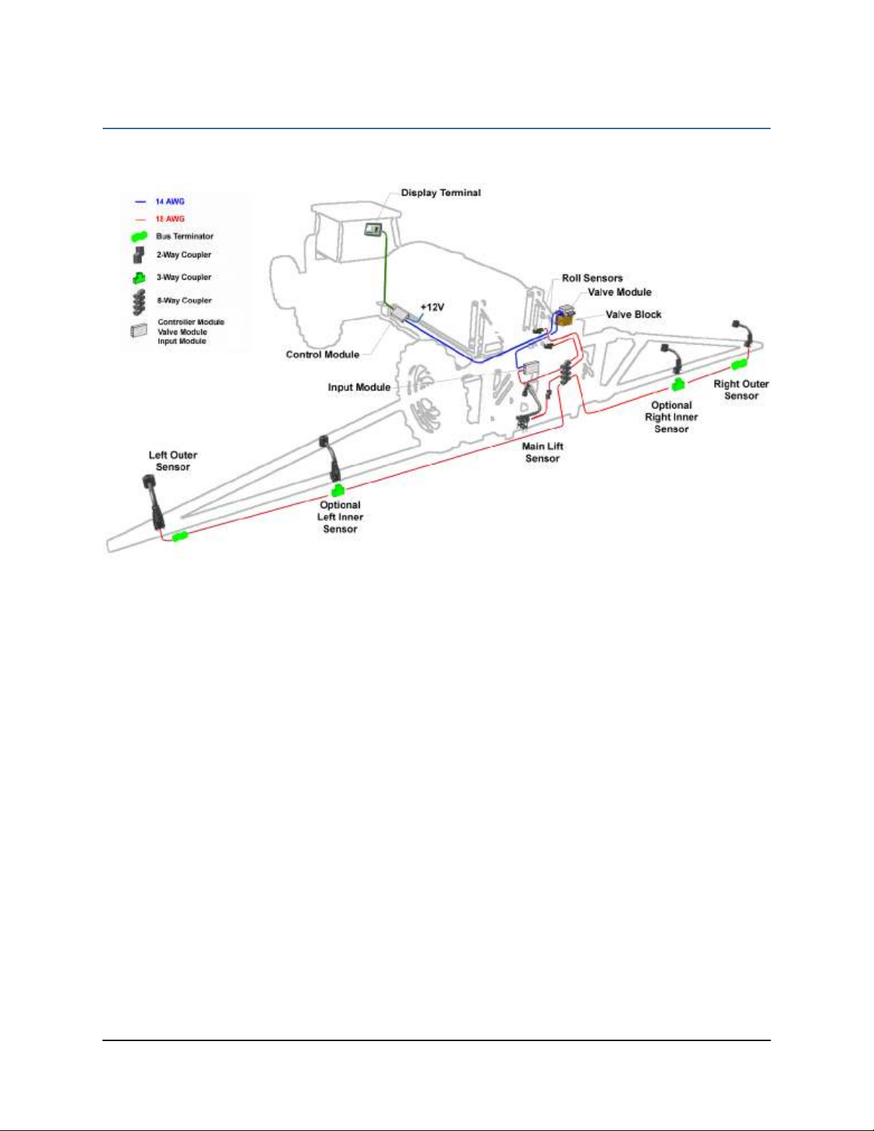
2 General UC5 System Layout
Figure 1 illustrates the general layout of the UC5 system components
Figure 1: General UC5 System Layout
3
3 Kit Parts
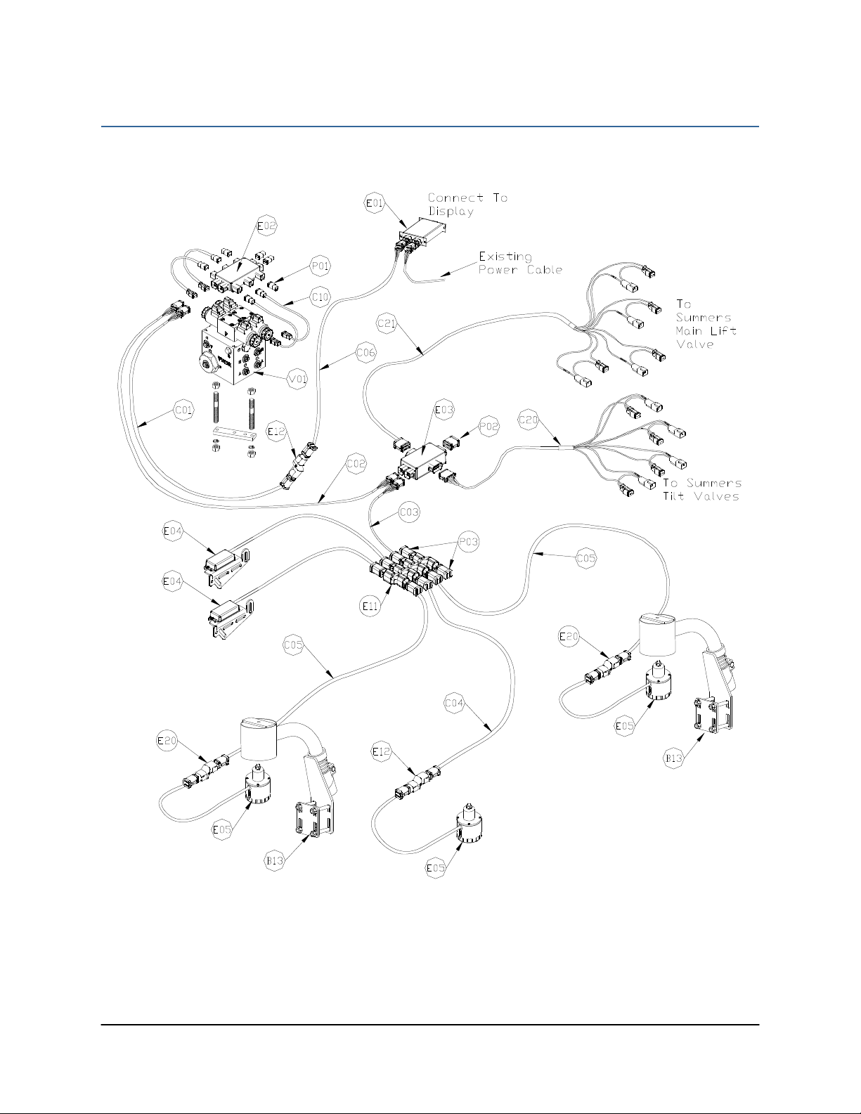
3.1 Kit Overview
Figure 2: SM02 System Parts

4
3.2 ydraulic Plumbing
Figure 3: SM02 Hydraulic Plumbing

5
3.3 List of Parts
Item Part Number Name Quantity
B05 44706-01 KIT CABLE TIE BLACK 10 PCS 21 IN 150 PCS 7 5 IN 1
B13 44728 MOUNTING BRACKET COMPLETE UC4 BREAKAWAY EXTENDED 2
C01 43220-10 CABLE UC5 NETWORK 14 AWG 10M 1
C02 43220-01 CABLE UC5 NETWORK 14 AWG 1M 1
C03 43210-03 CABLE UC5 NETWORK 18 AWG 3M 1
C04 43210-01 CABLE UC5 NETWORK 18 AWG 1M 1
C05 43210-20 CABLE UC5 NETWORK 18 AWG 20M 2
C06 43220-05 CABLE UC5 NETWORK 14 AWG 5M 1
C10 43230-04 CABLE UC5 VALVE 2PIN DT TO 2PIN DT 4
C20 43240-01 CABLE UC5 INTERFACE TILT DT 1
C21 43240-07 CABLE UC5 INTERFACE MAIN DT (WITH AUX 1 & 2) 1
E01 43710 UC5 CONTROLLER MODULE 1
E02 43720 UC5 VALVE MODULE 1
E03 43732 UC5 INPUT MODULE PASS THRU 1
E04 43740 UC5 ROLL SENSOR 2
E05 43750 UC5 ULTRASONIC SENSOR 3
E11* 43765 UC5 NETWORK COUPLER 8-WAY 1
E12 43764 UC5 NETWORK COUPLER 2-WAY 2
E20* 43764T UC5 NETWORK COUPLER 2-WAY WITH TERMINATOR 2
H01 44863-01 HOSE ASSEMBLY 122R2-06 36 IN L 6FJX 6FJX 2
H02 44863-30 HOSE ASSEMBLY 122R2-06 372 IN L 8MB 6FJX WITH QUICK COUPLER 2
H10 44865-30 HYDRAULICS FITTING KIT - SM1 1
M02 UC5-BC-SM02-INST MANUAL INSTALLATION UC5 SUMMERS 1
P01 106034 UC5 NETWORK 2 PIN PLUG 4
P02 106035 UC5 NETWORK 12 PIN PLUG (A-KEY) 1
P03 105882 UC5 NETWORK 6 PIN PLUG 2
V01* 44963D VALVE BLOCK ASSEMBLY 2 STATION CC/LS PROP DT 4 BOLT 1
* See Substitution Parts
6
3.4 Substitution Parts
Substitution parts will in no way affect the operation of the system provided that they are
installed as directed.
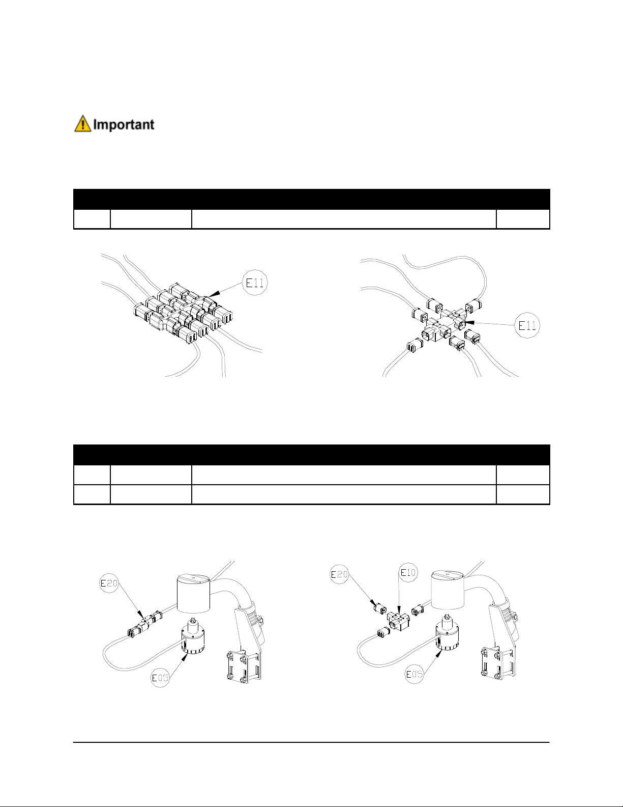
Item E11 – 8-way coupler (43765) may be substituted with:
Item Part Number Name Quantity
E11* 43762 UC5 NETWORK COUPLER 6-WAY 1
43765 43762
43765 Replaced with a 43762
Item E20 – 2-way coupler with terminator (43764T) may be substituted with:
Item Part Number Name Quantity
E10 43760 UC5 NETWORK COUPLER 3-WAY 2
E20* 43780 UC5 NETWORK TERMINATOR 2
Install the UC5 Network Terminator (E20*) into the third connector on the UC5 Network 3-way
Coupler (E10) (shown below). It is now a drop-in replacement for the 43764T (E20).
43764T Replaced with a 43760 and 43780

7
Item V01 – 2 Station Valve Block (44963D) may be substituted with:
Item Part Number Name Quantity
V01 44933D VALVE BLOCK ASSEM UC4-BC 2-STATION CC/LS VARIABLE RATE 1
The 44933D is a direct replacement for the 44963D. Both valve blocks function the same. The
blocks are identifiable by the filter cap shape and by the part number stamped on the side.
The A and B ports are opposite on each valve block so verify that the hoses are being
connected to the correct port. The raise lines always go to the “B” port and the lower lines
go to the “A” port.
44933D Valve Block Shown Alongside 44963D Valve Block
Filter Cap Part
Number
Part
Number
Filter Cap
8
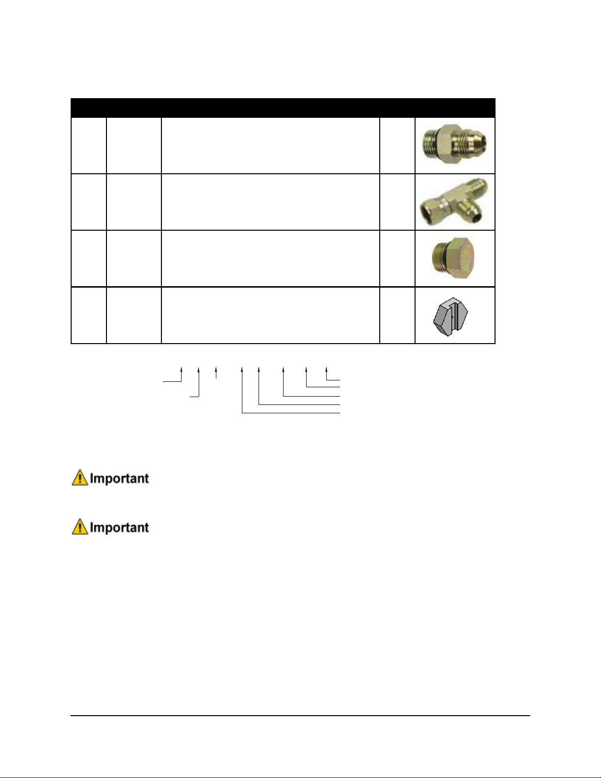
3.5 ydraulic Fitting Kit Details (P/N: 44865-30)
Item Part Number Name Quantity Picture
F02 103312 MALE ADAPTER - 6MB 6MJ 4
F03 103839 TEE ADAPTER - 6FJXR 6MJT 2
F04 104369 PLUG - 6MBP 2
F05 44928 ORIFICE INSERT 047 IN ONE WAY 2
6 M B - 6 M OR X 90
SIZE IN
1/16
TH'S
GENDER: MALE
OR FEMALE
90
°
ANGLE
SWIVEL
TYPE
GENDER
SIZE
TYPE:
B - ORB
- IC
OR - FLAT
FACE
P - PIPE
Fitting Name
Example:
The use of dielectric grease is not recommended on any NORAC electrical connections.
To ensure all stainless steel hardware does not gall or seize apply a light coating of the
supplied Permatex Anti-seize grease to all threaded parts upon installation. Permatex Anti-
seize lubricant is preferred, but other similar anti-seize products may be used.

9
4 Pre-Install Checklist
The pre-install checklist is necessary to check the existing sprayer functionality before the
installation.
1. Unfold the sprayer over a flat, unobstructed area (i.e. no power lines…etc.).
2. Ensure all boom-fold operations are functional (place a check mark in boxes below).
3. Bring engine to field-operational RPM and record below.
4. Record the time (seconds) it takes for a full stroke for all boom functions. To ensure
repeatable measurements, take the average of 3 trials.
5. Not all sprayers will have the functions listed below in Figure 4.
Ensure the boom has sufficient travel so it does not contact the ground during these tests.
Figure 4: Pre-Install Boom Speeds

10
5 Ultrasonic Sensor Installation
5.1 Ultrasonic Sensor Serial Number Arrangement
When installing the UC5 sensors, start with the smallest serial number on the left-hand side, and
proceed to the largest serial number on the right hand side. Each UC5 sensor has a serial number
stamped on the sensor housing.
Figure 5: Sensor Serial Number Arrangement

11
5.2 Ultrasonic Sensor Mounting Guidelines
The following guidelines will ensure optimal sensor performance and prevent sensor
measurement error. These rules should be followed for both the wing sensors and the main lift
(middle) sensor.
1. In its lowest position, the sensor must be 9 inches (23 cm) or more from the ground (A).
2. The centerline of the acoustic cone should be approximately vertical at normal operating
heights (A).
3. The bottom of the sensor must be at least 9 inches in front of the spray nozzles and boom
structure (B). (This does not apply for the main lift sensor)
4. The bottom of the sensor must be at least 9 inches above the spray nozzles (C).
5. Ensure there are no other obstructions with a 12 inch (23 cm) diameter circle projected
directly below the sensor (D).
Figure 6: Sensor Mounting Guidelines

12
5.3 Wing Sensor Installation
1. The sensor bracket should be oriented forward (ahead of the boom).
2. Typically the best mounting location for the wing sensor brackets will be near the end of the
boom tips, approximately two feet (60cm) from the end.
3. Depending on the boom design, some breakaway sections will lift upwards as they break
back. If the sensor is mounted to this portion of the boom, the system will force the boom
downwards towards the ground as the boom folds backwards.
4. Mount the NORAC UC5 ultrasonic sensor into the sensor bracket and run the sensor cable
through the sensor tube.
A problem can arise if a sensor is not mounted correctly. It is possible for the sensor to
read off of the boom instead of the ground. This may only become apparent once the
controller is switched from soil to crop mode.
Also be careful that the sensor bracket does not collide with any other part of the boom
when the boom is folded to transport position. If possible, mount the sensor brackets while
the booms are folded to ensure they will not cause interference.
Figure 7: Sensor Reading Off Boom
13
5.4 Main Lift Sensor Installation
1. There are a variety of ways to mount the main lift bracket on most sprayers. The bracket
should position the sensor approximately in the center of the sprayer, forward of the boom.
An example of this mounting is illustrated in Figure 8.
Figure 8: Example Mounting of the Main Lift Bracket
Avoid mounting the main lift sensor over or near a wheel-track. Measurements from the
wheel-track do not provide an accurate crop height and will cause measurement and
control error.
Ensure the bracket does not collide with any other part of the sprayer throughout the full
range of main lift motion.
14
6 Roll Sensor Installation
6.1 Bracket Assembly
1. Securely mount the roll sensors to the included roll sensor brackets using the #6 machine
screw and nylon lock-nuts.
2. The orientation of the mounted roll sensor to the roll sensor bracket will depend on the
bracket mounting. The roll sensor CANbus connector must be pointing towards the right
side of the sprayer.
Figure 9: Mounting Roll Sensor to Bracket
Figure 10: Roll Sensor Orientation - Connector Facing Right Wing
15
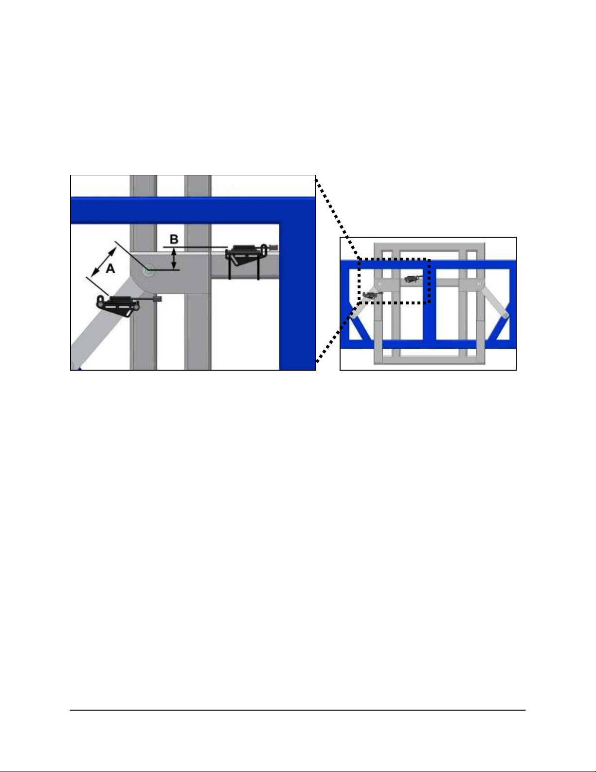
6.2 Roll Sensor Mounting Guidelines: Trapeze-Suspended Booms
1. When mounting the roll sensors, mount one to the trapeze link (boom frame) and one to the
trapeze support (chassis). For optimal performance, minimize the distance from the boom
frame roll sensor to the pivot point (A) and minimize the vertical distance between the
chassis roll sensor and the pivot point (B).
Figure 11: Roll Sensor Mounting on a Trapeze Suspended Boom
2. Ensure the roll sensors are relatively level when the sprayer boom and chassis are level.
3. Both roll sensor cables should be pointing towards the right hand wing of the sprayer.
4. Ensure both roll sensors are mounted adequately and that the cables provide enough slack to
allow sufficient boom roll.
16
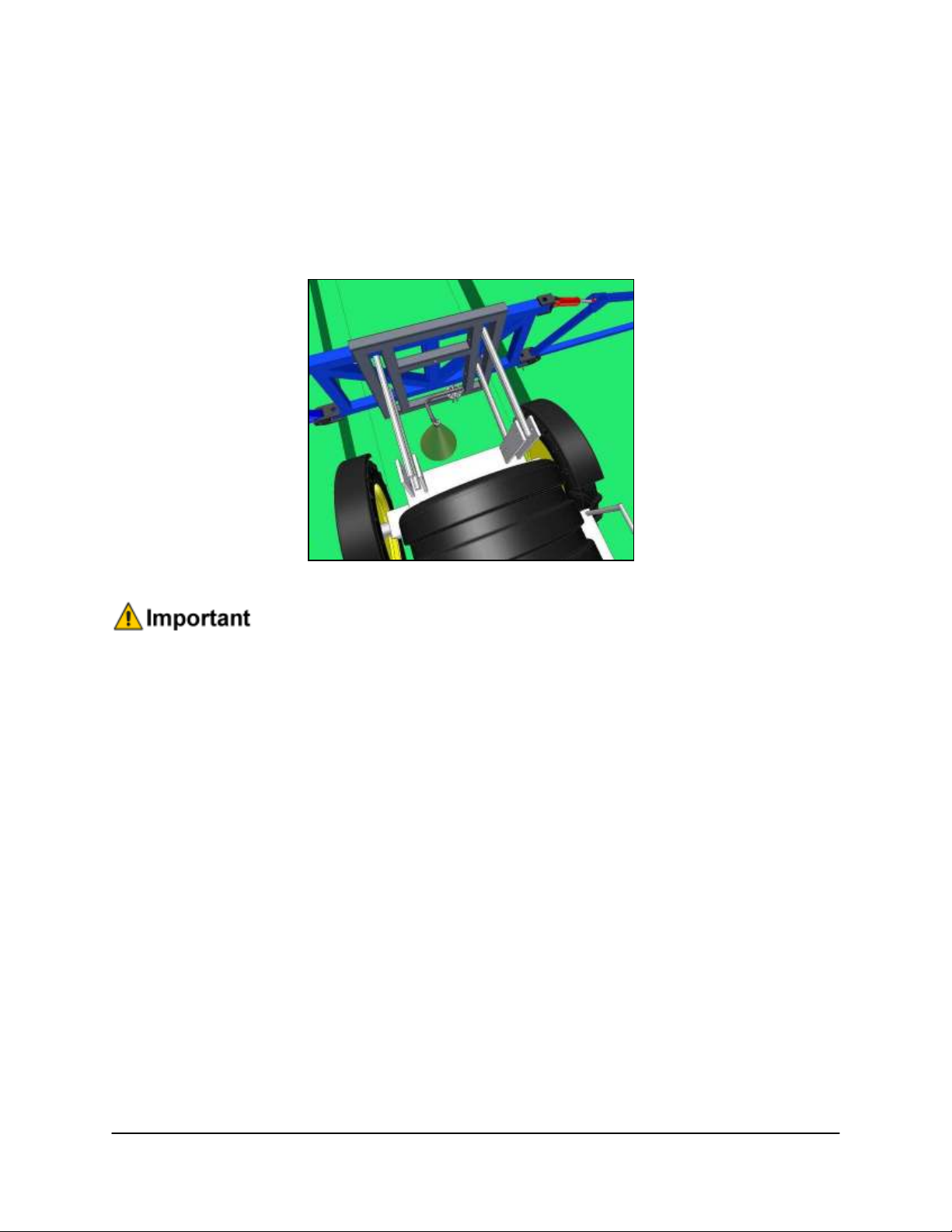
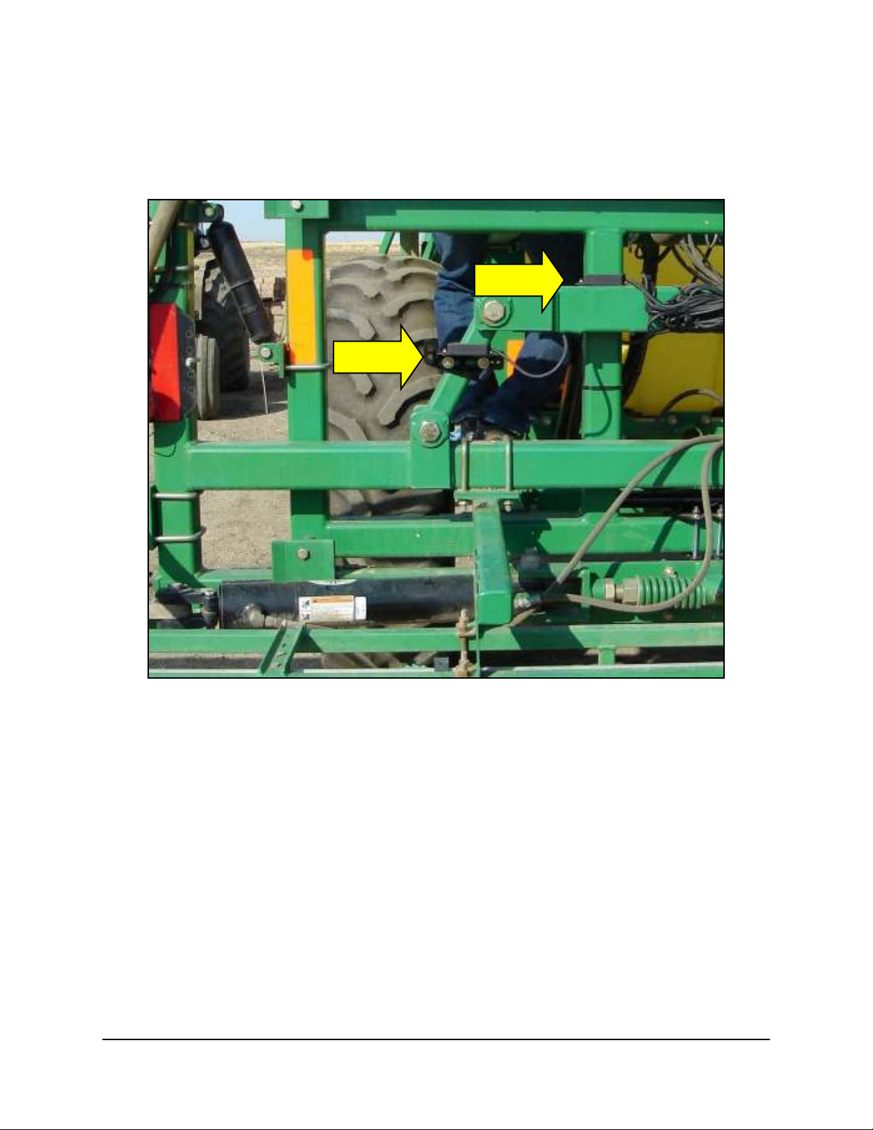
6.3 Roll Sensor Mounting on a Summers Sprayer
Figure 12: Roll Sensor Mounting (Viewed from the rear of sprayer)

17
7 Module Installation
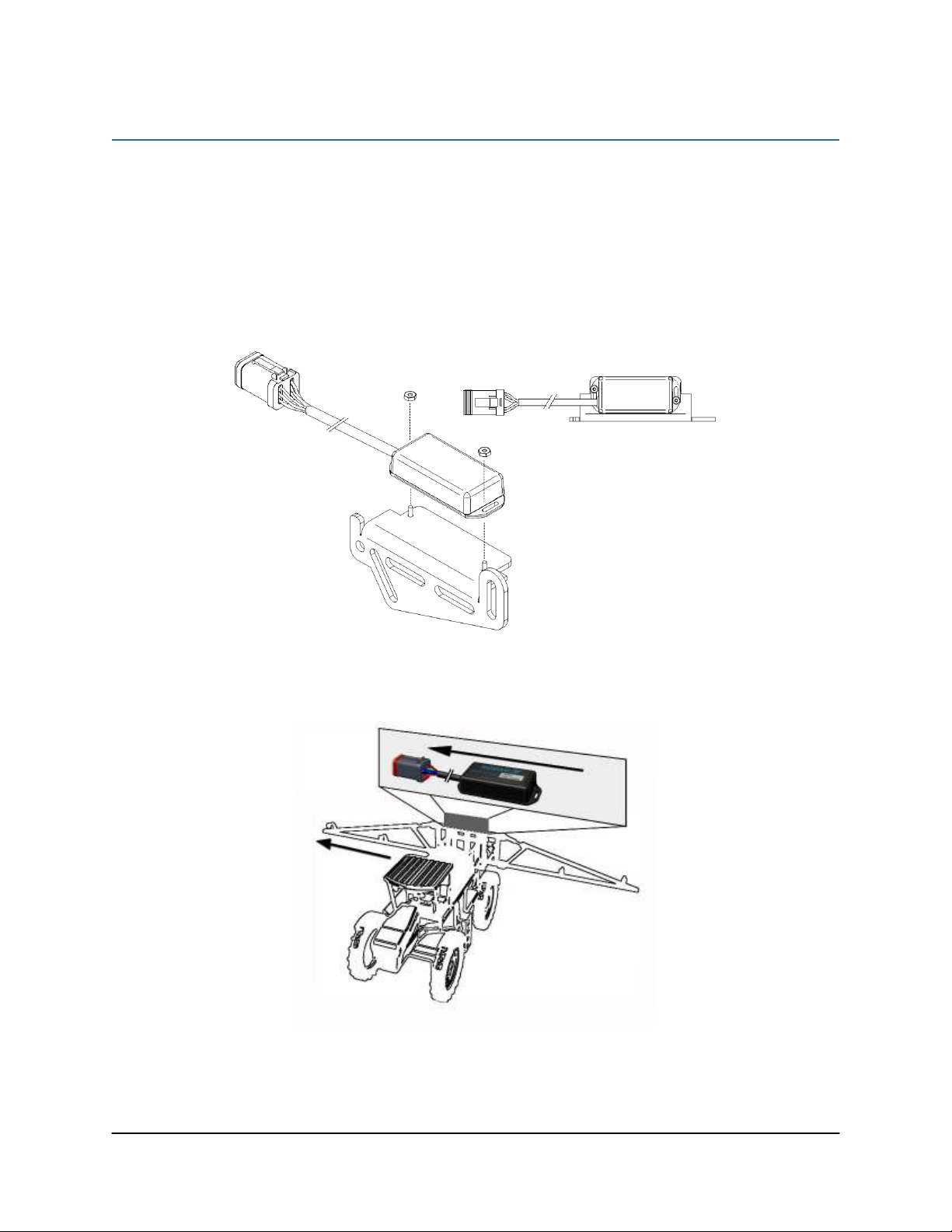
7.1 Control Module
1. Refer to Figure 1 and Figure 13.
2. Securely mount the control module (E01) in the cab or on the sprayer. Refer to the display
kit installation manual to determine the best mounting location.
3. Connect the display terminal to the control module using the display CANbus cable. This
cable must be connected to the end of the control module with only one Deutsch connector.
4. Connect the existing power cable to one of the two CANbus connectors on the other end of
the control module.
5. Route cable C06 from the other CANbus connector to the 2-way coupler (E12). Connect
cable C01 to the other side of the 2-way coupler.
6. The 2-way coupler (E12) should be located near the hitch to act as a hitch disconnect if the
control module is mounted on the tractor. If the control module is mounted on the sprayer,
E12 and C06 may not be required.
Figure 13: Control Module Mounting
Other manuals for UC5 Topcon X30
55
Table of contents
Other Norac Farm Equipment manuals

Norac
Norac UC4+ User manual

Norac
Norac UC5 Topcon X30 User manual

Norac
Norac UC4+ User manual

Norac
Norac UC5 Topcon X30 User manual

Norac
Norac UC4.5 User manual

Norac
Norac UC4 Total Control User manual

Norac
Norac UCB Sx275 User manual

Norac
Norac UC4+ User manual

Norac
Norac UC5 Sx275 User manual

Norac
Norac UC4.5 User manual
Popular Farm Equipment manuals by other brands

Schaffert
Schaffert Rebounder Mounting instructions

Stocks AG
Stocks AG Fan Jet Pro Plus 65 Original Operating Manual and parts list

Cumberland
Cumberland Integra Feed-Link Installation and operation manual

BROWN
BROWN BDHP-1250 Owner's/operator's manual

Molon
Molon BCS operating instructions

Vaderstad
Vaderstad Rapid Series instructions


