Lavit LB115 Series User manual

1
Service Manual
Rev
-
B
Lavit LB115 Dispenser
FOR TECHNICAL ASSISTANCE
PLEASE CALL 1.855.750.5377

2
About this Manual
This Technical Manual is designed to support the service departments and field technicians of
Lavit’s authorized Distributors and Dealers.
The manual provides an overview of the Lavit Beverage Dispenser and recommended installation,
operation, and troubleshooting procedures. The manual also provides basic instructions for repair
and replacement of various components as necessary to maintain the full functionality of the Lavit
Beverage Dispenser.
Conventions used in this manual include:
BOLD CAPITALIZED TEXT is used to highlight critical information for the technician.
When the symbol appears, critical safety information is provided.
Lavit also provides Distributors and Dealers with Technical Bulletins and Service Bulletins.
Technical Bulletins are generally information contained in this manual but provided in a one- or
two-page bulletin for ease of access and use. For example, “How to Calibrate Your Lavit Dispenser”
is a Technical Bulletin provided for easy reference but the same information is contained in this
full manual.
Service Bulletins are related to current service or operating issues with the Lavit Beverage
System and provide critical guidance to correct a known issue or to monitor a possible condition
in the field.
At all times while servicing or your Lavit Dispenser please ensure that you
have turned off the power to the unit.

3
Table of Contents
Section 1: The Lavit BeverageDispenser Overview Page: 4
Section 2:Installation:
Installation Overview Page: 10
Pre-Deliver Inspection Page: 10
Locating the Lavit Dispenser Page: 11
Section 2a: POU Installation Page: 12
Section 2b: Bottled Water Installation Page: 17
Section 2c: Aqua Host Installation Page: 23
Water Calibration Page: 26
Section 3: Operating the Lavit Dispenser Page: 29
Section 4: Cleaning theLavit Dispenser Page: 35
Section 5: Service Screens
Section 6: Information Screens
Page: 37
Page: 40
Section 7: Troubleshooting Page: 42
Section 8: Decommissioning and Moving the Dispenser Page: 45
Section 9: Service and Repair:
Removing the Top Panel Page: 47
Removing the Side and Rear Panels Page: 48
Appendices: Parts Drawings, Parts Lists, Schematics Page: 49

4
NOTES:

Section 1: The Lavit Beverage Dispenser Overview
Lavit Document: TM170915
---
A
5

5
The Lavit Cold Beverage Dispenser
The Lavit Beverage Dispenser is designed to dispense either cold still water, cold sparkling water,
or a Lavit beverage, which can be made with either still water or sparkling water, depending on
the beverage type. When selecting a Lavit beverage using sparkling water, the beverage can be
crafted using a choice of carbonation levels: soft, medium, or full.
The Lavit Cold Beverage Capsule
The Lavit beverage capsule and top lidding are made from aluminum and
are fully recyclable without any additional processing. Each capsule is
designed to be a single use mixing chamber for the beverage selection. This
approach eliminates all possible beverage cross contamination.
Cold Mix Chamber
The primary function of the Lavit Beverage Dispenser is to make cold, flavored, and healthy
drinks. The mix chamber is designed to receive a Lavit beverage capsule, crack and peel the top
lidding, introduce a mix stream, and process and merge the beverage stream with a still or
sparkling water finishing stream. The key components of the mix chamber include the blue
capsule tray where a capsule is placed, the silicone water nozzle for the mix and finishing streams,
and the entire capsule carriage which tilts forward to dispense the mixed beverage into the
finishing stream. The carriage begins and ends it cycling at the HOME POSITION.
Cold Tanks
The cold still water tank has a storage capacity of 1.3 gallon (5 liter) of cold water and is made
from 304 stainless steel. Sparkling water is made in a secondary 0.26-gallon (1 liter) capacity
tank made from 304 stainless steel. The sparkling water tank sits inside the cold still water tank
in a unique tank in tank system. The whole assembly is made cold by a fully immersed direct chill
evaporator. The cold-water temperature is microprocessor controlled, is non
---
adjustable, and is
factory set at 37.4F (3C)
Filter and CO2 Cylinder Side Compartment
The door on the right side of the dispenser provides access to the filter and CO2 cylinder
compartment. The recommended Lavit ECO3 filter or a Lavit Bottled Water pump is mounted
towards the front of the compartment. Connection points for both are molded in the compartment
side wall. The CO2 pressure regulator and gas cylinder are mounted towards the rear of the
compartment.
6
Rear Panel
The rear panel on the Lavit Dispenser has the following features:
CO2 Purge –the toggle on the upper left (from the front of the unit) allows CO2 gas to be
purged from the system. Purging is required on the initial set up and at any time gas
pressure is to be released from the unit.
Power Socket –the supplied power cord attaches into the power socket on the lower right.
Power Switch –the power switch is used to power on or power off the unit.
Water Inlet –a quick connect ¼” fitting for the inlet water line. When initially installing
the water, line push the line in a second time when water pressure is applied to ensure
a complete seal.
Water Drain –the drain on the lower left of the panel is used to drain down the 5-liter
cold water tank. The drain plug is secured with a screw. To remove the drain plug rotate it
90 degrees to the left.
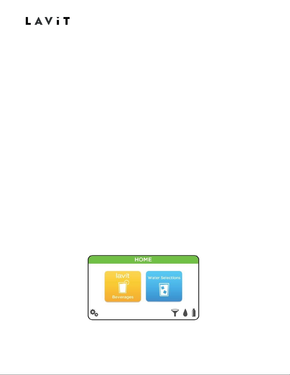
Microprocessor Control and Touchscreen
The Lavit Dispenser is a microprocessor-controlled beverage and water dispenser with a LCD
touch screen providing the user an operating interface and to display process information. The
microprocessor controls temperature, water filling, water levels, capsule mixing, water finishing
streams, operating of the mix chamber, and dispenser status. The touchscreen will default to the
HOME SCREEN when the unit is ready to dispense water or a beverage.
ANY SCREEN (OTHER THAN THE HOME SCREEN) CAN BE EXITED AT ANY TIME BY PRESSING
THE BACK ARROW ON THE UPPER LEFT OF THE DISPLAYED SCREEN.
7
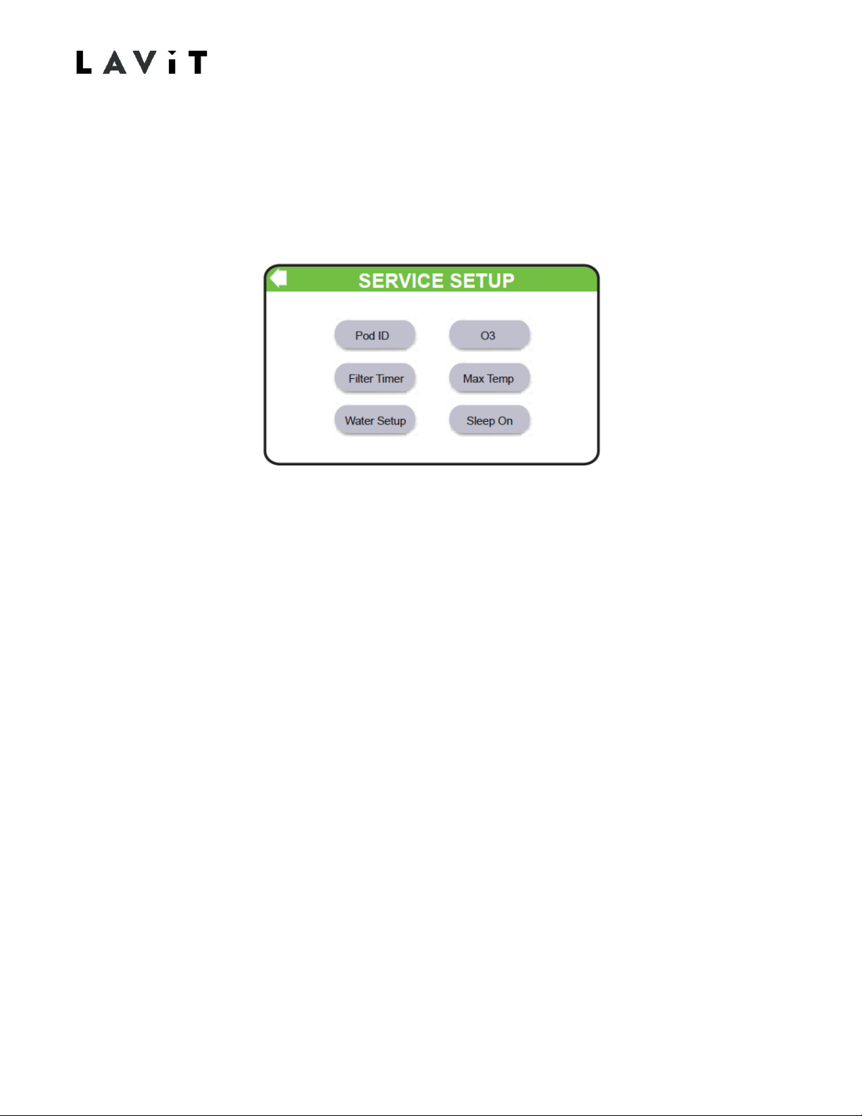
Service Screen and Date/Time Settings
The date and time set up screen and the service menu can be easily accessed by pressing the gear icon in
the lower left of the Home Screen. After setting the date and time the service menu can be
accessed by pressing the SERVICE SET UP icon. USE THE PASSWORD TO ENTER THE SERVICE
MENU IS 8888.
From the Service Menu the technician can set the ozone on time, the allowed Max Temp for
beverage and water dispensing, enabling or disabling Sleep Mode and the Filter Timer, and
entering a Water Set Up Screen. The Pod ID setting is currently non
---
active for future use.
Lavit Button
The black Lavit button MUST BE PUSHED TO DISPENSE WATER OR A BEVERAGE. The use of a
final dispense button allows the user to verify their drink selection and ensure a cup is placed
under the dispense point prior to dispensing.
The button has a halo ring which changes color based upon the dispenser status. The halo colors
are:
Blue halo= Stand by. Unit will dispense cold still water when pressed.
Green halo = Ready to dispense after menu selections are complete.
Flashing green = Dispensing. PRESSING THE BUTTON WHILE FLASHING GREEN
TERMINATES THE DISPENSE AND SENDS THE BEVERAGE CARRIAGE TO HOME
POSITION.
Red Halo = Waiting for selections to be completed.
Flashing red halo = Fault condition. REFER TO TOUCHSCREEN GRAPHIC.

8
Disinfection
The cold tank water system is disinfected every 24 hours at 3 am (factory setting). The Ozone
Generator will turn on for 1 hour and as the generator runs, ozone is injected into the cold tank by
means of the cold tank circulation pump. This ensures that the entire content of the cold tank is
exposed to ozone every 24 hours. The ozone start time can be changed as required through the
service screen.
Filtration for POU installation
Lavit recommends using the Lavit ECO3 Filter for dispenser installations to a building’s main
water supply (POU). The filter is a 0.5-micron carbon block rated at 1500 gallons, and is NSF
certified to standard 42 Classes 1, chlorine taste and odor, and standard 53 cysts, lead and
asbestos. The Lavit ECO3 also has a NSF certified multi-layer sediment particulate membrane to
protect the carbon block. In any known high sediment water areas please use a pre
---
sediment filter
before the machine and filter.
Antimicrobial Protection
The contact parts of the Lavit Dispenser are protected by Lavit through silver ion technology. A
silver ion additive is added to the raw plastic parts as they are manufactured. This inhibits the
growth of bacteria on contact surfaces. The additive will not leach out and will be effective for the
life of the machine.
Bottled Water Installation
In addition to a POU installation, the Lavit Dispenser is designed to also work with a 5
---
gallon
bottle water supply. A bottled water installation will require the fitting of a Lavit bottle water
pump kit, which is supplied separately.
Transporting the Lavit Dispenser
The Lavit Unit should not be transported with water in either tank or with a CO2 cylinder attached.
Please drain the unit of all water per the instructions provided in this manual before moving the
unit. The CO2 cylinder should also be removed and the CO2 regulator secured in place with tape.
CO2 Cylinders
CO2 cylinders are provided to distributors and dealers by authorized Lavit distributors. Each filled
cylinder contains 1.5 pounds of liquid CO2 which when released to atmosphere converts to a gas.
Sparkling water is created by mixing CO2 gas in cold chilled water. Each cylinder is filled with food
grade or beverage grade CO2. It is imperative that a minimum of food grade gas is provided. It is
critical that distributors and dealers and their service personnel properly handle, store, and
transport filled cylinders.
TM170915-B
9
CO2 Cylinder Handling
1.
DO NOT expose filled Lavit CO2 cylinders to temperatures above
120°F (49°C) or below 34°F (1°C). If exposed to heat for aperiod of
time the safety pressure seal on the cylinder will burst and may
cause injury if the cylinder is in close proximity to thetechnician.
2.
DO NOT wash the Lavit CO2 bottles in the dishwasher and DO NOT
rinse the bottle in hot water. DO NOT place the bottles in the
freezer. Doing so will compromise the integrity of thecarbonating
bottle material and may result in serious personalinjury.
3.
DO NOT use any CO2 bottle not specifically designed to work with
the Lavit dispenser. Use only a LAVIT labeled cylinder providedby
an authorized Lavit Cylinder Distributor.
4.
The Lavit CO2 cylinder should be properly installed prior to
operating the Lavit dispenser.
5.
The CO2 cylinder should be inspected prior to use for any dents,
punctures, or other damage. If any are detected, DO NOT use the
CO2 bottle and contact your cylinderprovider.
6.
Mishandling the Lavit CO2 cylinder can result in serious personal
injury. Always keep CO2 bottle away from any heat source and out
of direct sunlight. Do not store or leave filled cylinders in aservice
van for long periods of time especially when experiencing warm
weather.
7.
Do not transport the Lavit Dispenser with the CO2 cylinder
connected.

Section 2: Installation
Installation Overview
The Lavit Beverage Dispenser is designed to be installed in one of three ways.
Option 1: A POU connection to a mains water supply, fitted with a Lavit ECO3 filter.
Option 2: A 5-gallon bottled water supply using a Lavit pump kit.
Option 3: Connected to an AquaHost water dispenser with an AquaHost pump kit.
Instructions for installing a Lavit dispenser for each option are provided below.
Pre-Delivery Inspection
Prior to installing the Lavit Dispenser in one of three installation options, please conduct an
inspection of the unit.
1.
Unpack the unit. Verify that the power cord, drip tray, and CO2 pressure regulator are
included in the side walls of the foam packaging. Remove and setaside.
2.
Remove the plastic bag from the unit and inspect the unit for any shipping damage. Open
and close the mix chamber to ensure proper operation. Open and close the side panel
access door to ensure properfunctioning.
3.
Verify that the blue capsule tray in the mix chamber is properly attached and free tomove.
4.
Ensure that the silicone nozzle is the mix chamber is tightly fastened and properlyaligned
straight up and down.
5.
Note any damage and report any damage to your servicesupervisor.
6.
It is recommended that all packaging material is saved and returned to yourservice
location to be used when transporting or storing a dispenser in the future.
Lavit Document: TM170915
---
A 10
TM170915-B
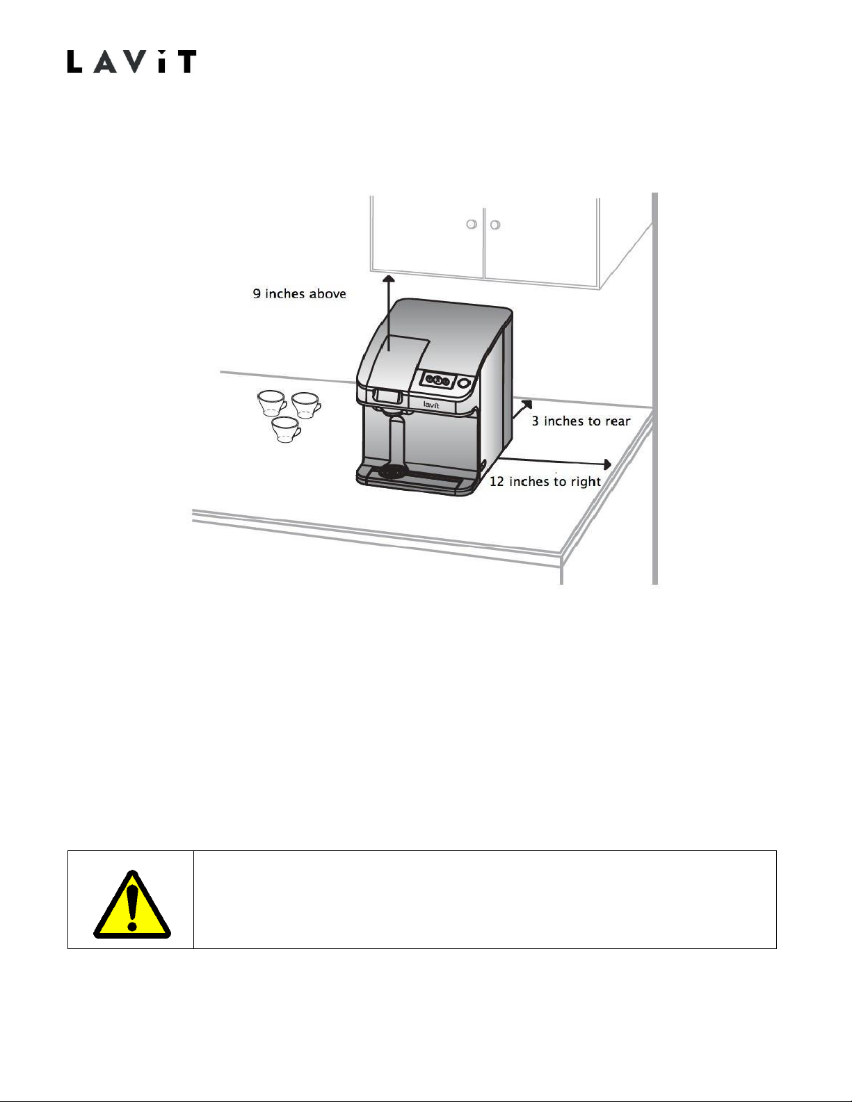
Locating the Lavit Dispenser
1. Place the dispenser on a firm flat surface, adjacent to the power supply and water supply.
2. Ensure there is an air gap (3 inches) in the rear of theunit.
3. Ensure there is clearance (12 inches) on the right side to open the side door to access the
side compartment.
4. Ensure there is enough space above the mix chamber (9 inches) to properly open andclose
the chamber.
5. Do not install the dispenser in direct sunlight or adjacent to a heat source.
Proceed to the specific installation instructions for your selected water supply option.
11 TM170915-B
Dispensers should not be installed using a power extension cord. It is
advised that all power sockets have been polarity checked and have a
suitable earth connection.
12
TM170915-B
Section 2a: POU Installation
Required Materials and Tools
Lavit ECO3 Filter Kit
¼” NSF approved water tubing
40 psi pressure reducing valve (¼” quick connect fittings recommended)
¼’ In line check valve
¼” Shut off valve
Tubing cutter
" It is the responsibility of the installer to follow all local codes during installation"
Installation Instructions
1.
Ensure that the minimum water inlet pressure from the mains supply is 28 psi. Connectto
the water supply using a standard three-way valve connected to an under sink cold water
shut off valve or connect in another acceptable manner to allow for ¼” water tubing to be
connected. Run the tubing to the dispenser so that there is enough excess tubing to allow
movement of the dispenser for service inplace.
2.
Properly secure the tubing with appropriate fasteners to minimize the possibility of the
tubing being pulled off the mains connection and to provide an aesthetic installation for the
customer.
3.
Install the 40-psi pressure reducing valve, the in-line check valve, and the shut off valve on
the water inlet tubing. From the mains connection it is recommended that the sequence is
the PRV followed by the check valve and then the shut off valve. As an option a second shut
off valve can be installed prior to the PRV to allow the removal of all downstream
components.
4.
Flush the Lavit ECO3 filter outside of the dispenser to ensure no carbon fines can enterthe
dispenser.
Dispensers in a POU installation must be connected to a known potable
water supply. It is recommended that the power cord be connected to a
GFI outlet.

13
TM170915-B
5.
Attached the supplied filter mounting bracket in the side compartment. Connection points
are molded into the side wall.
6.
Locate the water pipe that is looped inside the side compartment. Cut the loop.
YES
7.
Place the two ends of the pipe into the in and out push fits on the Lavit ECO3 filter. The
right side of loop is water in. Mount the filter into the mountingsaddle.
8.
Before connecting the water supply to the dispenser, flush the water supply to waste, and if
the water is running clear, connect the water supply to the rear of the dispenser.
NO
X
Lavit Document: TM170915
---
A
15
TM170915-B
9.
IN ANY KNOWN AREA WITH HIGH SEDIMENT WATER, A PRE
---
SEDIMENT FILTER
SHOULD BE INSTALLED BEFORE THEDISPENSER.
10.
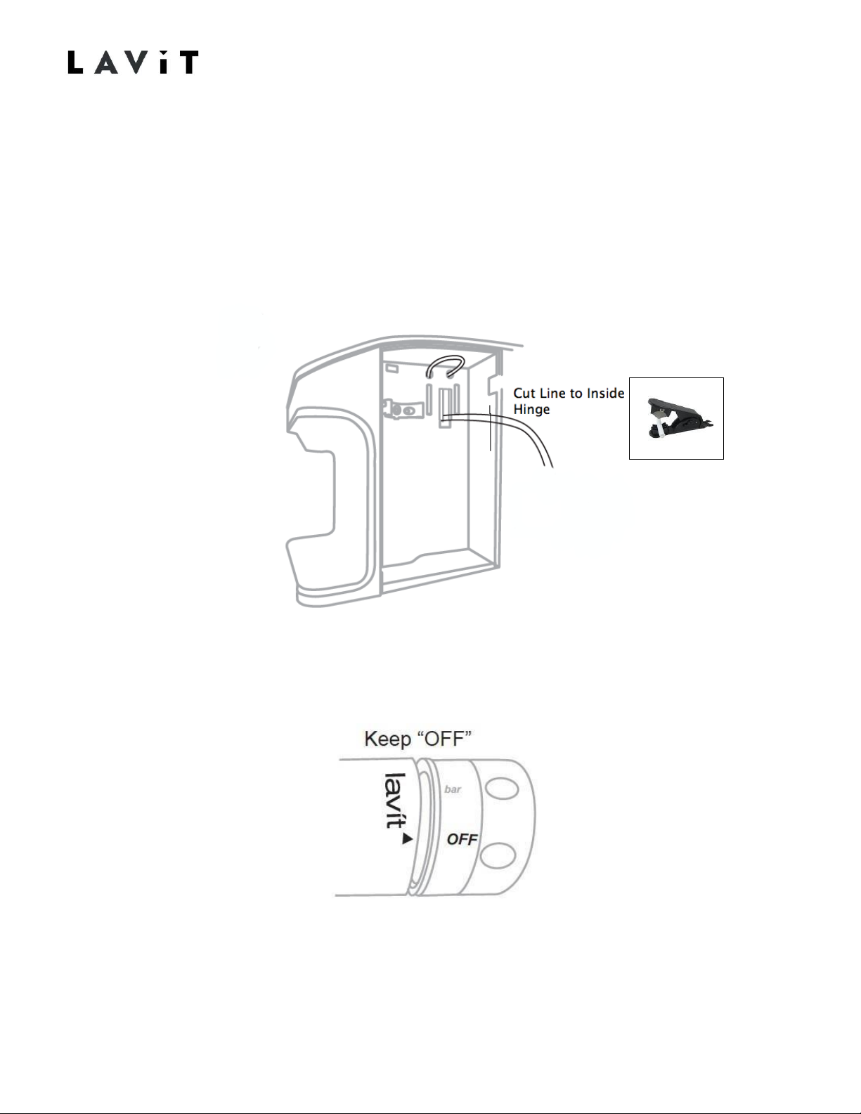
Ensure that the Power Switch is in the OFF position (bottom in). Connect the power cord.
11.
Locate the CO2 inlet pressure line inside the side compartment. Extend the line awayfrom
the dispenser and trim the line using a tubing cutter so that the final length of the tube
extends to the inside of the doorhinge.
12.
Connect the supplied CO2 pressure regulator to the inlet tubing. Ensure that the regulator is
fully off by turning the knob fullycounterclockwise.
13.
Wipe the bottle threads and screw the supplied 1.5-pound CO2 cylinder onto the
regulator. DO NOT TURN THE GAS PRESSURE ON AT THIS POINT. Place the cylinder
in the side compartment ensuring the side doorproperly closes.

Lavit Document: TM170915
---
A
16
TM170915-B
14.
Turn on the water supply. Turn the power switch to ON at the rear ofthe dispenser.
15.
The dispenser will self
---
check on every power up and if OK will go to the LCD home screen
and the Lavit Button halo will bered.
16.
TO FILL THE DISPENSER WITH WATER, PUSH THE LAVIT BUTTON AND THE
DISPENSER WILL START TO FILL. The screen will display a WATER TANKFILLING
SCREEN.
17.
When the water tanks are half filled, the compressor will turn on and start to chill. Thesoda
pump will also turn on when the water tank is half full. The HOME screen will appear.
18.
When the HOME screen appears turn the CO2 gas pressure on. SET THE REGULATORTO
3.5 BAR OF PRESSURE BY ROTATING THE KNOB CLOCKWISE. 3.5 BAR OF PRESSURE
(50 PSI) IS INDICATED AT THE BEGINNING OF THE RED SCALE ON THE REGULATOR.
The soda tank will fill with CO2 gas.
19.
Purge any air from the system by toggling the CO2 Purge Valve located in the rear ofthe
unit. Purge gas about 3 times for 2 seconds each time.
The dispenser is now “live” and proper safety precautions should be
followed if any panels are removed from the unit.

20.
If the water tanks do not fill within 5 minutes the water inlet valve will automatically close.
This feature is a safety feature that prevents the continuous running of water in the case of
a water leak. An error screen indicating a possible leak will be displayed. To clear the
dispenser of this condition, turn the power off and then backon.
21.
Push the Lavit Button again and the tanks will then automatically fill to capacity and shut
off and the Lavit button halo will beblue.
22.
While the water tanks are filling and the compressor is chilling the water, set thecurrent
date and time by pressing the gear shaped Service Icon on the lower left of the HOME
screen.
23.
From the Date/Time Screen, enter the Service Menu by pressing the Service Setup icon.
24.
From the Service Menu select and make the following choices:
Enter MAX TEMP and DISABLE (when disabled the icon will read “Enable”).
Set the Filter Timer to ENABLE (when enabled the icon will read “Disable”) and reset the
timer if the filter life is to be tracked by the unit. The filter icon on the HOME screen will
change to RED when enabled and six months have passed.
Enable or Disable Sleep Mode.
Select WATER SETUP and display the water calibration screen. Calibrate the three
water streams (mix, still and sparkling) by following the Water Calibration
Procedure found at the end of this Section 2, Page 25.
25.
After completing the water calibration return to the HOME screen by pressing the Return
Arrow in the upper left of the touchscreen to back out of all servicescreens.
26.
Check for CO2 leaks, check for waterleaks.
27.
The dispenser should now be ready to use after the dispenser reaches temperature. The
first cooling cycle will take approximately 70 minutes.
28.
Enable and set the MAX TEMP if so desired to ensure that every beverage is servedchilled.
It is recommended that this feature is Disabled unless a user has asked for colder
beverages.
16 TM170915-B

17
TM170915-B
Section 2b: Bottled WaterInstallation
Required Materials and Tools
A five-gallon bottle of water
Lavit Bottled Water Pump Kit
¼” NSF approved water tubing (black color recommended)
Tubing cutter
Installation Instructions
1. Locate the water pipe that is looped inside the sidecompartment.
YES
It is recommended that the power cord be connected to a GFI outlet.
NO
X
18
TM170915-B
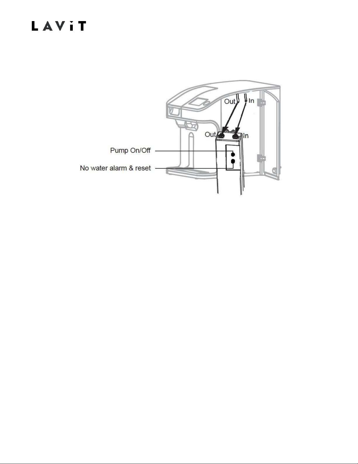
2. Cut the water pipe loop and place the two ends of the pipe into the Lavit Bottled Water
Pump marked in and out. The right-hand side of the loop is water in.
3. Fit the pump into the side compartment using the slots in the bottom of the panel and the
screw attachment points. Plug the pump into the supplied power socket inside the
compartment. Ensure the Pump Power Switch isOFF.
4. Place the 5-gallon bottle within six (6) feet of the machine and remove the bottleseal.
5. Fit the water bayonet into the bottle and seal the bottle with the cap located on the water
bayonet.
6. Connect the ¼” water tubing from the top of the water bayonet to the waterinlet
connection at rear of the dispenser.
7. Ensure that the Dispenser Power Switch is in the OFF position (bottom in). Connect the
power cord.
8. Locate the CO2 inlet pressure line inside the side compartment. Extend the line awayfrom
the dispenser and trim the line using a tubing cutter so that the final length of the tube
extends to or slightly past the inside of the door hinge.

19
TM170915-B
9. Connect the supplied CO2 pressure regulator to the inlet tubing. Ensure that the regulator is
fully off by turning the knob fullycounterclockwise.
10. Screw the supplied 1.5-pound CO2 cylinder onto the regulator. DO NOT TURN THE GAS
PRESSURE ON AT THIS POINT. Place the cylinder in the side compartment ensuring the
side door properly closes.
11. Turn the power switch to ON at the rear of thedispenser.
The dispenser is now “live” and proper safety precautions should be
followed if any panels are removed from the unit.
Other manuals for LB115 Series
1
Table of contents
Other Lavit Dispenser manuals


Popular Dispenser manuals by other brands


Mirabella International
Mirabella International Genio I005006 quick start guide

Idex
Idex Fast & Fluid X-SMART Technical note

BULMAN Products
BULMAN Products R999 8-ROLL Instructions for assembly and use

Creator
Creator CRT-531 Series Product specification

WEPA
WEPA Satino 332540 Assembly instructions

Metasys
Metasys META TOUCH Instructions for use