Lavo Solutions CLEANJET User manual
Rev. AA| 122020
1
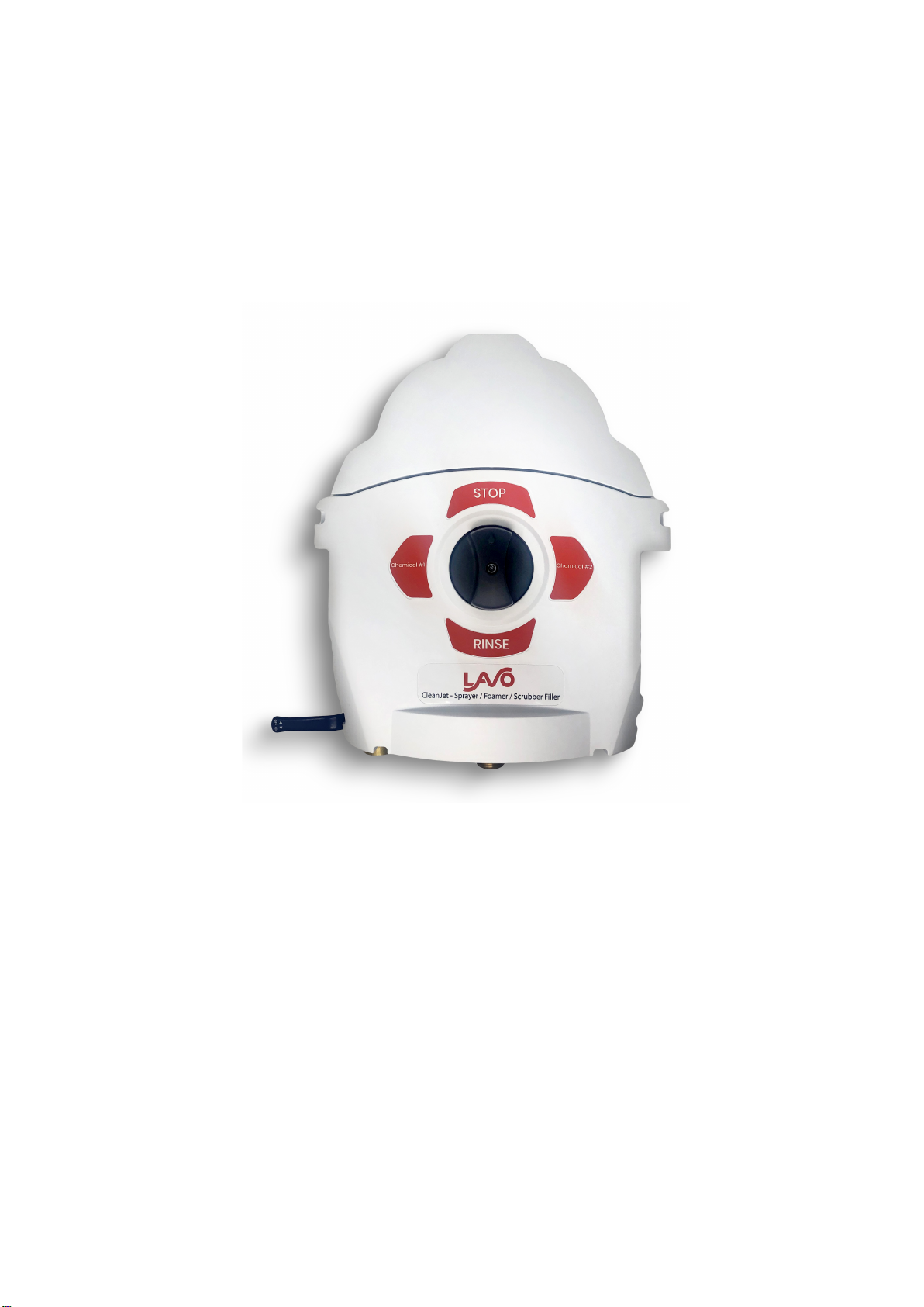
CLEANJET
SPRAYER / FOAMER

2
TECHNICAL CHARACTERISTICS:
Water supply
connection Connection on left side with elbow
Inlet connection type Female ¾” GHT
Outlet connection type Male ¾” GHT
Chemical product
channel flow rate
Water supply of 8gal/min flow rate and 50psi: 2.5 gal/min
Rinse channel flow rate
Water supply of 8gal/min at 50psi: 3.4 gal/min
Maximum dimensions
H = 400mm (15.75”)
L = 330mm (13”)
D = 160mm (6.3”)
Working pressure Min 22 PSI (1.5 bar) Max 85 PSI (6 bar)
Optimum: 30 – 60 PSI (2 – 4 bar)
Temperature
Max 140°F (60°C)
PLEASE READ THE FOLLOWING WARNINGS BEFORE INSTALLING OR SERVICING THE CLEANING
STATION
Make sure that the water supply pressure is between 22 -85 PSI, in case of excessive pressure use a
pressure regulator to avoid breackage.
Make sure that the water supply temperature does notexceed 140° (60°C)
The ProTwin’s fittings have been tested with commonly used liquid detergents mixed with water.
Check that the detergent used is compatible with polypropylene.
Install the station near as possible to a water supply connection point.
Mount the CleanJet considering easy access for cleaning and routine maintenance.
WARNING: Disconnect water supply before servicing theCleanJet.
WARNING: THE MAXIMUM OPERATING PRESSURE is 6bar (85 PSI) and isintended asa maximum
static pressure applicable to thesystem. Care should betaken that the equipment cannot produce
scenarios of over pressurization, which could cause damage to the structure of the system. The use
of a pressure reducer isalways recommended and theinstallation of a tap onthewater outlet of the
system which can be closed when thesystem itself is not in use.
WARNING: Follow common safety procedures. Use adequate protection forthe eyes, face, hands,
and clothing.
We constantly work to improve our products and reserve the right to make changes at any time
without prior notice.
Failure to follow these safety precautions may cause personal injury or damage to the equipment.
Only use recommended accessories.
3
INSTALLATION
The CleanJet should be installed where it is easily connected to the water supply.
Before mounting, check that allvalves can be easily operated and exposed surfaces are accessible for cleaning
and routine maintenance.
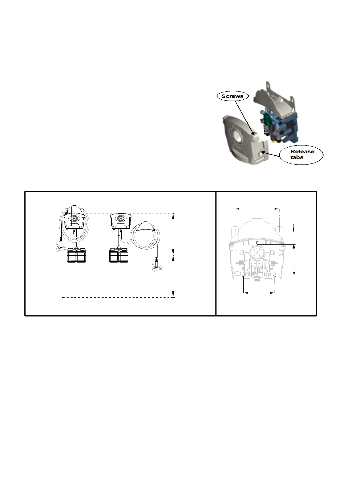
Positioning and drilling plans:
Remove the CleanJet from the box and remove the cover byremoving
the screws at the top and pressing the release tabs. You can now access
to the mounting holes (located on the rear panel). Mount the CleanJet on
the wall using the supplied anchors, screws and washers.
The versatility of the CleanJet allows the hose bracket to be installed as
an integrated part of the unit or mounted independently as pictured
below.
Figure 2 – Drilling plans and positioning
GROUND
700 mm (27,56’’)
700 mm (27,56’’)
248.9 mm
(9,
8’’)
177.8 mm
(7,
0’’)
198.1 mm
(7,8’’)
78.7 mm
(3,1’’)
PACKAGE CONTENTS:
1. CleanJet System
2. Suction hose 1.83m / 6ft(1 roll for eachproduct)
3. Hose bracket
4. Complete installation kit:
-Water inlet elbow fitting ¾” GHT
-Plastic hoseclamps (2 for each product)
-15 metering tips (1 bag for each product)
-4 ultra-lean tips (1 bag for each product)
-Foot valve (1 for each product)
-Ceramic weight (1for each product)
- Suction elbow (1 for each product)
-Wall anchors (3 pcs)
-Screws (3 pcs)
-Washers (3 pcs)

4
How to install:
Figure 3 –Installation
1. Disconnect the 90° water inlet from the station by rotating it 45°counterclockwise to unlock it.Then connect
the water inlet hose;
2. Reconnect the 90° inlet fitting back into the CleanJet,tilting by45°to its side, consecutively rotate 45°
clockwise to lock the connection;
3. Secure the hose to CleanJet through the clamp and the screw supplied as shown;
4. Drill the top ofthe product container using a 3/8 drill bit;
5. Slide the cap, ceramic weight onto the bootom of the supplied product pick up tube. Connect to the foot
valve as in figure above.
6. Connect the pick up tube to the CleanJet as follows:
a. Select the ' nozzle calibration produced according to the table to be inserted into the aspiration valve as
shown in the figure;
b. Insert the link at 90°;
c. For each product, place the aspiration tube into the fitting 90° and then fix it with plastic cable tie.
7. Attach the discharge hose to ¾ Male GHT fitting at the bottom of the CleanJet;
8. Attach the dosing gun.
5
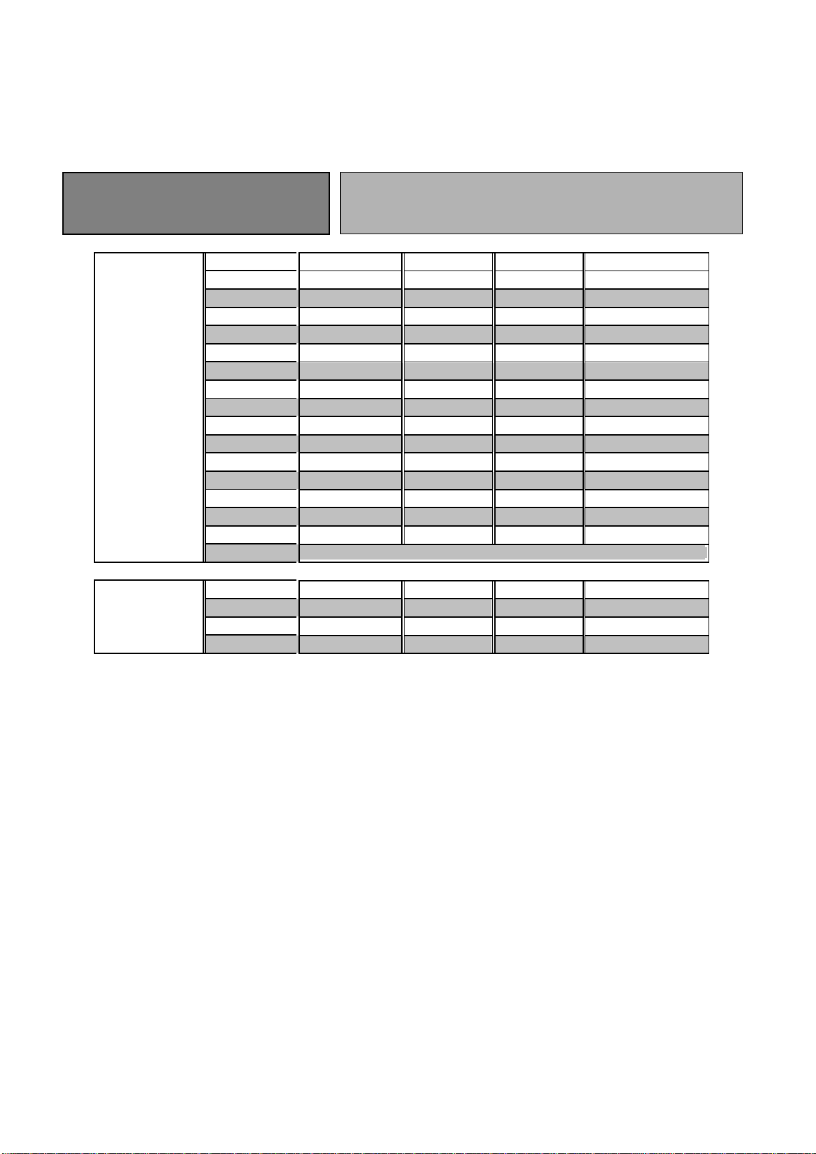
DILUTION RATIO CHART
The dilution ratio can be achieved by using one of the 19 supplied metering tips;
Metering tips have small openings of decreasing diameter and are distinguished by different colors.
Table 1 below shows the dilution ratio’s of the various colored tips assuming chemical viscosity of 1 cps (water thin)
(Water supply pressure and flow rates will vary so adjustments in the field may be necessary)
The dilution ratios refer to a static pressure of
50PSI with products
having a viscosity of 1 cps
Black Venturi
2.5 GPM
STANDARD
MEASUREMENT
TIP
Tip color: Oz/Gal gr/lt % Ratio
No tips 24.8 186 18.6 5:1
Grey 24.5 183 18,3 5:1
Black 24.4 183 18.2 5:1
Beige 20.9 156 15.6 6:1
Red 15.2 114 11.4 9:1
White 10.2 76 7.6 12:1
Blue 8.4 63 6.3 15:1
Tan 6.5 49 4.9 20:1
Green 4.4 33 3.3 32:1
Orange 4.0 27 2.7 36:1
Brown 2.6 19.6 2 50:1
Yellow 2.016.5 1.6 64:1
Acqua 1.8 13.4 1.3 70:1
Purple 1.0 6.6 0.6 128:1
Pink 0.503.4 0.3 256:1
Transparent No drill
ULTRAFINE TIP
Lime 0.40 2,6 0.26 320:1
Burgundy 0.35 2,8 0.28 365:1
Pumpkin 0.30 2,2 0.22 425:1
Copper 0.251,8 0.18 512:1
Table 1 – The dilution values given in this table are measured at a flow rate of 8 gpm and a supply
pressure of 50psi with a delivery hose of 15.24 m (50 ft).
The values in the table should be considered only as a reference, as they are dependent on many variables such
as water flow rate, pressure, chemical viscosity, temperature of the water etc.
To obtain a proper dilution it is recommended to perform the calibration as follows:
1. Fill a graduated container with the chemical product.
2. Using the Table 1, select and insert the metering tip closest to the desired dilution ratio for the product.
3. Insert the suction hose into the graduated container.
4. Select the product to be calibrated by turning the selector to the left or to the right.
5. Activate the spray gun and discharge into a container until the suction and delivery hoses are completely
full and free of air (check for air bubbles at the input and for a steady output stream).
6. Mark the level in the graduated container.
7. Turn on the spray gun to the maximum and discharge into a 1 liter or 1 gallon container (or other volumes
considering the proportion).
8. Turn off the spray gun when the container is completely filled.
9. Read the amount of product in the graduated container.
10. The difference of level between the point 8 and 5 indicates the amount of mixed product per gallon.
11. Repeat the calibration procedure for the other product.
A transparent metering tip is also provided without a pre-drilled opening.
This tip can be manually drilled to obtain a customized degree of dilution.

6
Operation
The CleanJet allows the dilution of chemical products with water without
using an electrical or other power source. The only energy required is the
pressure of the water passing through a venturi which aspirates a metered
chemical into the flow of water through the venturi.
When the installation is properly completed,follow these steps:
1. Turn on the water supply
2. Select the desired cleaning phase
-Selector facing up “OFF”
-Selector facing right “PRODUCT N° 1”
-Selector facing down “RINSE”
-Selector facing left “PRODUCT N° 2”
3. Activate the spray gun
4. Shut off the water supply when not in use
Accessories & Options:
The CleanJet Sprayer comes standard with Blue Trigger Sprayer (PN 410-0001) and 25 ft Black Hose (PN 410-0002).
Black Fan Foaming attachment (no air required) - PN 410-0007
Faoming Wand and Gauge System (air required) - PN 410-0008
AutoScubber Gun Attachment; 3/4" Hose Barb Fitting - PN 400-0048
25ft Hose; 3/4" FGHT x 3/4" MGHT - PN 410-0002 (not shown)

7
MAINTENANCE
ITEM CAUSE MAINTENANCE
Water supply filter
Limestone deposits on the screen
Replace
Debris or solids on the screen
Clean with water or replace
Venturi Limestone deposits
Clean or replace
(Warning: do not use tools to
remove the lime deposits because
you can affect the functioning of the
venturi; only use anti lime products)
Congealed product
Clean with water
Non-return valves
Worn
Replace
Congealed product
Clean if possible or Replace
Foot filters
Worn
Replace
Congealed product
Clean if possible orReplace
TROUBLESHOOTING GUIDE
PROBLEM
CAUSE
REMEDY
No flow
No water supply Open the water supply outside tap
Select product or rinse
Turn on the spray gun
Clogged hydraulic parts
Check the water supply filter (input
station)
Check the venturi
Product is not mixed or not dosed
correctly
The foot filter is clogged
Clean or replace the filter
The calibration nozzle is clogged
Clean or replace the nozzle
Insufficient water pressure
A minimum pressure of 22PSI is
required for correct operation; if the
pressure is not correct, contact a
plumber
The chemical product container is
empty
Refill or change the chemical
product container
The suction hose is not properly
connected to the elbow fitting
Check that the suction hose is
properly connected to the fitting, use
a clamp for a better grip
The suction hose is crimped
somewhere
Check that the suction hose is
properly positioned
Debris or Solids in the venturi
Clean with water or compressed air
(Warning: do not use tools to
remove the lime deposits because
you can affect the functioning of the
venturi; only use anti lime products)
Concentration too high The nozzle is not fully inserted or
Wrong metering tip
Check that the nozzle is securely
plugged into the non return valve or
select a smaller metering tip
The chemical product container
fills with water.
The non return valve is clogged or
worn
Clean or replace the non return
valve

Page | 27
Terms & Conditions
Company warrants its Goods to be free from material defects in material and workmanship for a period of one year ex-
cept: i. when Goods have been modified following delivery and/or subject to improper handling, storage, installation, op-
eration, or maintenance unless those modifications have been authorized in writing by Seller. ii. when an item is pur-
chased by Company as a component part of the Goods, except to the extent to which such item or items are covered by
the warranty, if any, of the original manufacturer. iii. when an item which is a component part of the product has been
furnished by Buyer. iv. no warranty of a component part shall extend beyond the warranty period of the device in which
such component part is incorporated. b. There is no implied warranty of merchantability or of fitness for particular pur-
pose and there are no warranties of any nature except as set forth in paragraph 3 herein. Any claim by Buyer made pur-
suant to Company’s warranty must be made in writing. Company shall have the right to inspect the Goods claimed to be
defective and shall have the right to determine the cause of such alleged defect. All Goods replaced or repaired by Com-
pany under its warranty shall be replaced or repaired F.O.B. Company’s facility. Buyer must notify Company, in writing,
within fifteen (15) days from receipt of Goods of any obvious defect in the product, or shortages, or Company shall have
no obligation to correct such defect. Company shall have the option of re-inspection at Buyer’s plant or its own before
allowing or disallowing Buyer’s claim. Defects that do not impair service shall not be a cause for rejection or recovery
under any warranty. Buyer assumes full responsibility for the use and application of the product. Buyer accepts Compa-
ny’s design and material selection and specifications in placing this order unless other specifications are agreed to in
writing by both parties prior to the manufacture of Goods by Company. Statements and data relating to Products on
Seller’s literature and website are not intended to define the performance of the product in actual usage or in com-
bination with other equipment or processes. These statements should not be used by Customer solely as an indication
of performance or suitability for specific applications or uses.
THE ABOVE WARRANTIES ARE THE SOLE AND EXCLUSIVE WARRANTIES MADE BY SELLER WITH RESPECT
TO ALL PRODUCTS AND SERVICES.
Components and spare parts such as O-rings, squeeze tubes, roller blocks and other plastic components are consid-
ered to be wear parts and are not warranted. Seller shall have no warranty or liability for product that was damaged dur-
ing shipment, product that is not being used in its recommended use, product that is not operated in accordance with the
operating manual and procedures, product that was not properly installed, product used in a manner that is inconsistent
with its designed purpose, product that is subject to a power surge or similar event, products that fail due to usage of a
non Lavo Solutions replacement or spare part or product that was not maintained in accordance with recommended
maintenance programs.
For full terms and conditions, please visit:
http://lavosolutions.com/LAVO-T&C-02-2018.pdf
Lavo Solutions, LLC
23192 Verdugo, Suite #D
Laguna Hills, CA 92653
O: 949-377-1250
W: www.lavosolutions.com
Table of contents
Other Lavo Solutions Paint Sprayer manuals

Popular Paint Sprayer manuals by other brands

C.A. Technologies
C.A. Technologies Tomahawk TG Product information

Graco
Graco GMAX 258731 Operation manual

IRONSIDE GARDEN
IRONSIDE GARDEN IGS 12P Recommendations for Use

Fimco
Fimco PRO Series owner's manual

Storch
Storch HVLP JustFinish Translation of the original instruction

WAGNER
WAGNER AG-19 owner's manual


BlueSpot
BlueSpot 07910 user manual

WAGNER
WAGNER ProjectPro 117 owner's manual

Graco
Graco 311736A Operation manual

Kobalt
Kobalt KSP 1024B-03 manual

Profi-AirBrush
Profi-AirBrush AB01117 operating instructions

Campbell Hausfeld
Campbell Hausfeld AL1860 - METAL Operating instructions and replacement parts list