Lavry DA10 User manual

LavryBlack Series
Model DA10
Digital to Analog Converter
Lavry Engineering, Inc.
P.O. Bo 4602
Rolling Bay, WA 98061
http://lavryengineering.com
email: tech[email protected]
Rev 3.52
August 6, 2009


LavryBlack DA10 Operation
1
MODEL DA10
The LavryBlack DA10 features:
- Ultra low jitter modes.
- Included sample rate conversion for non-standard rates.
- Potentiometer-free digitally controlled analog volume circuitry.
- High power discrete headphone output.
- XLR, Coa ial (RCA) and Optical (Toslink) digital inputs.
- Stereo/Mono switch.
- Audio Output Signal Polarity Inversion.
- Optional 19 inch rack mount kit for two LavryBlack units side-by-side in 1U space.
Rear Panel
CONNECTIONS:
CAUTION: Care must be taken when connecting the DA10 directly to the input of a power
amplifier or powered monitors to avoid speaker damage. It is suggest that before making any
connections, the DA10’s Volume setting be reduced to a low value (“00” to “05”). Please switch
OFF or disconnect power to all devices in your system before making input and output
connections to the DA10.
Connect a stereo digital audio INPUT from your source using any or all of the following:
- AES source using an XLR cable to the XLR connector labeled “aes.”
- Stereo optical source using a Toslink fiber to the optical connector.
- SPDIF source using a coa ial 75 Ohm RCA cable to the RCA connector labeled “spdif”.
Note:
- All the connectors can receive either AES/EBU (professional format) or “SPDIF” (consumer
format). For e ample, an XLR to RCA adapter can be used to feed a coa ial SPDIF signal to the
XLR input. “SPDIF” is the original name for stereo digital audio signals that are now known as the
AES3 or IEC 60958 type II “Consumer” format.
- In some cases, the format of the signal on an RCA output or an optical output can be set to
formats other than “Stereo” or “SPDIF.” For e ample, multi-disc DVD players that can play audio

LavryBlack DA10 Operation
2
CD’s may need to have the output format changed to “Stereo” before the DA10 can reproduce
the audio on a CD. Some computer interfaces have optical outputs that can be set to “ADAT”
which is multi channel, and is not compatible with the stereo digital input of the DA10.
Connect the XLR OUTPUTS to your destination device (recording studio equipment, receiver,
power amplifier, or powered speakers).
- Use XLR to RCA adapters or adapter cables to connect the XLR outputs of the DA10 to
equipment with RCA inputs.
- If connections are made to equipment with unbalanced inputs, please be sure to set the
internal jumpers for the proper unbalanced mode (typically “Pin 2 Hot”). Please see the
section titled CONFIGURING THE XLR OUTPUTS.
- The XLR marked left to the LEFT Channel of the destination.
- The XLR marked right to the RIGHT Channel of the destination.
- Please see the section titled “Determining the Correct DA10 Volume Setting for Your
System” for details on the correct Volume settings.
- Connect headphones to the HEADPHONE jack. The headphones can be plugged or
unplugged at any time. It is recommended that you unplug headphones when not in use.
CONFIGURING THE XLR OUTPUTS:
The unit is factory configured to operate in Balanced output mode. The balanced signal appears
on both PIN 2 and PIN 3 of the XLR outputs. PIN 1 is a ground connection for the cable shield.
The unit may be configured (via internal jumpers) to drive Unbalanced inputs.
Most XLR to RCA adaptors or adapter cables (such as a cable with XLR Female on one end and
an RCA plug or ¼ inch MONO plug on the other) work correctly as Balanced to Unbalanced
converters. However, you UST set the internal jumpers for the proper unbalanced
configuration when using adapters to avoid distortion of the audio output.
Here is an e ample of an XLR to RCA adapter (Female XLR to RCA socket):
The XLR pin of the adapter that connects to the center pin of the RCA plug is the “HOT” pin for
unbalanced operation. In most cases, this is Pin 2 of the XLR connector. Pin 1 and Pin 3 are
typically connected together and to the outer contact of the RCA connector.
Please see section G: “SETTING THE DA10’S INTERNAL JUMPERS” for additional information.
OPERATION:
A. INPUT SELECTOR, SAMPLE FREQUENCY INDICATORS, & LOCK LAMP
The switch labeled INPUT selects which digital audio input acts as the source for the audio
output. The three positions xlr, rca, and optical correspond to the input connectors on the back
panel.

LavryBlack DA10 Operation
3
- When the PLL mode is set to narrow or crystal and the DA10 receives a valid input signal, both
the “lock” lamp and the sample rate indicator that corresponds to the input’s sample frequency
illuminate. The input must have a sample frequency of 44.1, 48, 88.2, or 96 kHz.
- In wide PLL mode, all four sample frequency indicators illuminate to indicate the DA10 will
accept inputs with a sample frequency between 32 and 200 kHz. The “lock” lamp illuminates
when the DA10 is locked to a valid signal.
B. PLL SETTINGS:
- Use crystal or narrow settings for 44.1, 48, 88.2 and 96 kHz rates for optimum jitter rejection.
Crystal mode offers the highest level of jitter rejection, but narrow mode offers e cellent jitter
rejection as well.
- Use wide for all other sample frequencies between 30kHz and 200kHz.
It is advisable to select the PLL mode (crystal, narrow, or wide) before turning the DA10 “ON.”
Changing between crystal, narrow and wide while the power is ON may cause the DA10 to take
up to 50 seconds to reach optimal performance. Although audio is being reproduced after the
setting has been changed, the quality of the audio may improve over this period.
C. AVOIDING CLICKS:
The DA10 provides protection against its own “AC power ON clicks”.
The DA10 CANNOT protect against “power ON clicks or pops” from digital sources feeding the
DA10. ALWAYS apply AC power to digital sources connected to the DA10 before applying AC
power to the DA10, or reduce the volume to “00” before applying power to, or changing operating
modes of the digital source.
- The volume setting is “non-volatile” and is stored when you turn the AC power “OFF.” For this
reason, it is advisable to reduce the volume to a low setting or “mute” (00) before turning the AC
power “OFF” in systems where the DA10 is connected directly to power amps or powered
speakers.
- It is also advisable to apply AC power to the power amp or power monitors after the DA10 is
turned “on” when feeding them directly from the XLR outputs of the DA10 (no preamp or volume
control between the DA10 and power amps). Conversely, it is advisable to remove AC power
from the power amp or powered monitors prior to turning the DA10 “Off.”
Although care has been taken to minimize the possibility, switching between input sources (xlr,
rca, or optical) and PLL modes (wide, narrow or crystal) during operation may cause unwanted
clicks, especially when the signal is loud.
D. MODE and POLARITY SETTINGS:
Either stereo or mono, and normal or invert can be selected at any time during operation.
-MONO mode is provided for monitoring the “mono compatibility” of a mi , and is most often used
in professional recording applications. The MONO signal is the AVERAGE (sum divided by 2) of
the Left and Right signals. This approach helps to preserve the perceived volume level when
switching between stereo and mono while listening to typical stereo music program.
- The POLARITY switch affects the Polarity of both the main XLR outputs and the headphone
output and is labeled “normal” and “invert.”

LavryBlack DA10 Operation
4
The POLARITY setting is provided for two reasons:
1. To provide fle ibility with output connection wiring.
2. To allow the signal polarity to be corrected when it is inverted due to polarity inversion in
the recorded music or other equipment/wiring in your system.
- Please note that this function operates in all configurations of the XLR outputs- balanced,
unbalanced Pin 2 Hot, and unbalanced Pin 3 Hot. The “sense” of the function is reverse for
unbalanced Pin 2 Hot operation and balanced “Pin 2 +” wiring (please see the chart below).
Settings for most XLR to RCA adapters.
Polarity Switch Setting Balanced output Unbalanced Pin 2 Hot Unbalanced Pin 3 Hot
Normal Pin 2 +, Pin 3 - Inverted (-) Non-Inverted (+)
Invert Pin 2 -, Pin 3 + Non-Inverted (+) Inverted (-)
The Polarity of the signal affects the motion of the speaker reproducing the audio, and if incorrect
can affect the fidelity of the audio in a way that will vary with program material. If correct
throughout the recording and reproduction process, a positive air pressure at the microphone will
result in a positive pressure created by the speaker. If it is “inverted,” the speaker will move in the
opposite direction and the resulting acoustic signal will be less accurate. This means that if you
“invert” an inverted signal, it will have the correct Polarity! Because there is no way to detect if the
signal polarity is inverted before it reaches the DA10, there is no direct correspondence between
setting the switch to the “invert” position and whether or not the reproduced signal is actually
inverted. A surprising number of recordings have been made with the polarity inverted.
- Please Note: The audibility of incorrect signal polarity varies widely with music program material,
the audio system, and listening environment. It can range from very subtle to quite apparent.
E. VOLUME CONTROL:
The DA10 features a digitally controlled analog Volume circuit to control the volume of the XLR
and Headphone outputs. Even though the control is in discrete 1 dB steps, the change is
accomplished after the DA conversion in the analog domain. This means that the audio is always
converted at FULL RESOLUTION, regardless of the Volume output level.
This approach offers a number of advantages:
- E tremely consistent sound quality regardless of volume; much better than a traditional
potentiometer “knob” type of control.
- E cellent matching between channels at every volume setting for consistent stereo balance.
- Ease of reset-ability for listening or critical monitoring at a consistent level
- The volume setting is non volatile – the unit recalls the last setting when powered ON.
The volume control consists of the numerical display under the VOLUME legend, and the
up/down switch just to the right of the display. The volume can be controlled in 1 dB steps from
full volume (56) to the lowest volume (01). When the display indicates “00,” the signal is muted.
Holding the up/down switch in either position will cause the Volume setting to change
continuously until the switch is released or the setting reaches the end of the range.
Please be certain to configure the outputs of the DA10 for the proper balanced or unbalanced
setting to match the wiring and inputs of your system. See the section titled CONFIGURING THE
XLR OUTPUTS for details.
F. DETERMINING THE CORRECT VOLUME SETTING FOR YOUR SYSTEM
There are two ways the DA10 can be used to listen to digital audio sources through speakers:
1.) Connect the main output of the DA10 to the input of a receiver or preamp, set the DA10 to a
“fi ed” level, and adjust the speaker volume using the volume control of the receiver or preamp.

LavryBlack DA10 Operation
5
2.) Connect the main output of the DA10 directly to the input of a power amp or powered monitors
and use the Volume control of the DA10 to adjust the speaker volume.
PLEASE NOTE: When operating the DA10 connected directly to a power amp or powered
monitors, it is important to reduce the VOLU E of the DA10 to a very low setting BEFORE
turning the AC power of the power amp or monitors “ON!”
Because the DA10 is capable of driving professional level balanced inputs as well as consumer
level unbalanced (RCA) inputs, some care is needed when using the DA10 with unbalanced
consumer HiFi equipment. Although e ceeding the absolute ma imum input level of the HiFi
equipment is not likely to cause damage, it will reduce the quality of the listening e perience.
- The first time you use the DA10 feeding equipment with a volume control, it is recommended
that you start with the DA10 at a very low VOLUME setting, and raise the volume on the preamp
or receiver to a level you would use to listen to other inputs (Phono or FM radio, for e ample).
Switch to the input that the DA10 is feeding, and raise the VOLUME setting of the DA10 until the
acoustic volume is the same as other sources. Matching the acoustic level between sources will
almost certainly mean you are not e ceeding the input rating of your equipment!
There is wide variation in the absolute ma imum input level that HiFi equipment is capable of
accepting without distortion. When this level is e ceeded, the music program can be distorted
regardless of the volume setting of the HiFi equipment because the distortion may be caused
before the volume control. This could also occur when feeding a power amp or powered monitors
directly, especially if the input level control of the power amp/monitors is turned “down” very low.
It could be harder to detect in this situation, because the corresponding acoustic volume would
typically be very loud when this distortion occurs.
- Most consumer equipment with RCA inputs are designed to operate with an absolute ma imum
input level of 2V rms (which is 5.6 V peak-to-peak). When operating in unbalanced configuration,
the VOLUME setting on the DA10 that corresponds to this level is “46.” It is recommended to
check the specifications and confirm this corresponds to the absolute maximum input rating of
your equipment according to the manufacturer! If it does not, you should determine the correct
setting of the DA10 that is the absolute maximum setting for your system. Please see the section
titled “Determining the Correct DA10 Volume Setting for other input ratings” (below).
- For professional equipment with balanced inputs, a VOLUME setting of 56 corresponds to
+24dBu. Some professional equipment has a ma imum input rating of +18 dBu, which
corresponds to the VOLUME setting of “50” on the DA10 for balanced operation and “56” for
unbalanced operation.
In cases where the DA10 is feeding a consumer receiver or preamp, once the absolute ma imum
level has been established, the actual level used for typical listening may be lower than this value.
As a rule, if you switch between analog sources on the receiver or preamp and there is a large
difference in volume between other sources and the DA10, it is probably better to lower the
VOLUME setting of the DA10 below the absolute ma imum level if it is much louder than other
sources. It will probably take some e perimenting with different music program to establish a
good “working volume” with your system. There is a possibility that the optimum DA10 level
setting will still result in the DA10 being slightly louder than other sources. It is also recommended
that you not e ceed the absolute ma imum level, even with music program that has large
variations in level, because a loud peak could occur that would cause distortion.
In most cases, lowering the volume setting on the DA10 will degrade the signal quality less than
lowering the volume control on the receiver or preamp below a setting which is “normal” for other
analog sources (Phono, FM broadcast, etc.). The digitally controlled analog level circuitry of the
DA10 degrades the signal less than typical “knob” potentiometer volume controls on consumer
equipment, particularly at lower level settings.

LavryBlack DA10 Operation
6
Volume Setting XLR Balanced Operation
XLR Unbalanced Operation Headphone Level
56 24dBu 18dBu 18dBu
50 18dBu 12dBu 12dBu
--- --- --- ---
46 14dBu 8dBu 8dBu
--- --- --- ---
01 -31dBu -37dBu -37dBu
00 OFF OFF OFF
AES/EBU professional analog line levels:
Set to 56 for 24dBu balanced = 34.72V peak to peak = 12.28V rms
Set to 56 for 18dBu un-balanced = 17.36V peak to peak = 6.14V rms
A typical home power amp or powered speaker:
Set to 40 for 8dBu balanced = 5.6V peak to peak = 2V rms
Set to 46 for 8dBu unbalanced = 5.6V peak to peak = 2V rms
Determining the Correct DA10 Volume Setting for other input ratings-
Use the graph (below) to determine the proper ma imum Volume control setting of the DA10 for
other voltage values. For Volts rms or Volts p-p, find the voltage on the vertical scale on the right
side of the graph and trace horizontally until it intersects the relevant curve (solid for rms, dotted
for V peak to peak, balanced or unbalanced). At the point where the horizontal line intersects the
curve, trace straight down to the scale on the bottom of the graph to find the closest DA10
Volume control setting that will be the ma imum volume for your equipment’s inputs. Pro users
can use the vertical scale on the left edge of the graph for the same purpose using dBu units.
For e ample: if you find 2 volts on the right scale, and trace horizontally until it intersects the
dotted “Unbalanced Vrms” curve, then trace down to the bottom scale, it intersects at “46.”

LavryBlack DA10 Operation
7
If you have difficulty determining the correct setting, please contact
techsupport@lavryengineering.com once you have the manufacturer’s ratings for your
equipment.
G. SETTING THE DA10’S INTERNAL JUMPERS
The internal jumpers must be configured to match the wiring of the cables or adapters which will
be plugged into the DA10’s XLR outputs. If they are not set properly before the XLR outputs are
connected to unbalanced wiring or inputs, no damage will result because the outputs are
protected against “short circuits,” but the output signal ill be significantly distorted at higher
volume levels. It is therefore recommended that you open the DA10 and set the internal jumpers
to the correct setting before using the DA10 with unbalanced output connections.
If custom cables are an option, please also see section H- ALTERNATIVE WIRING FOR
UNBALANCED CONNECTIONS
Opening the DA10 to Set the Internal Jumpers-
1.) If you have not plugged the DA10 in yet, it is a good idea to do so first. Plug in the only the AC
power cord, and turn the DA10 “ON.” Start by reducing the volume setting to “00” and turn “OFF”
the AC power to the DA10.
2.) Disconnect all cable connected to the DA 10, including the AC power cord.
NEVER OPEN THE DA10 CASE WITHOUT FIRST DISCONNECTING THE AC POWER CORD!
3.) Ne t, place the DA10 bottom-side-up on a table and remove the five recessed Phillips head
screws located around the outer edge of the top cover with a #2 Phillips screwdriver.
4.) Carefully turn the DA10 over, and position it with the back panel near the edge of the table.
The back panel is the one with the input and output connectors.
5.) You may need to pick the DA10 up a bit to start sliding the bottom chassis out of the top
cover. Once it starts to come out, we would recommend grasping the chassis by placing your
thumb on the top edge of the rear panel with your four fingers under the bottom of the unit. Slide
the bottom chassis completely out of the top cover.
6.) Place the DA10 chassis so the front edge (with the switches and digital Volume display) is
closest to you, and you are looking towards the inside of the back panel.
7.) Looking down from above, the jumpers are located just in front of the XLR connectors
mounted in the back panel. Each “jumper” consists of a row of three small square gold pins set in
a black plastic base. The jumpers are actually the small rectangular black plastic blocks that are
placed across two of the three pins in each set.
8.) Look for the designation printed on the circuit board ne t to each set of pins. It will say either
“Hot, Pin 2, & Ground” or “Hot, Pin 3, & Ground” ne t to each set of pins. (see e ample below)
9.) Most standard adapters are wired for “Pin 2 Hot Unbalanced.” This means Pin 3 is connected
to Pin 1 (which is “ground”); setting the jumpers for “Pin 2 Hot Unbalanced” operation will be used
for the first e ample. Skip to step (11) for “Pin 3 Hot Unbalanced” settings.
To set the jumpers for “Pin 2 Hot Unbalanced” operation:
10.) The jumpers that need to move are the ones labeled: “Hot, Pin 3, & Ground.” Pull the small
rectangular black plastic jumper straight “up” and off of the two pins it is on and re-position it to
slide back down on the two pins labeled “Pin 3” and “Ground.” Once you have done this for both
left and right XLR connector, you are done with this part. Please go to step (12).

LavryBlack DA10 Operation
8
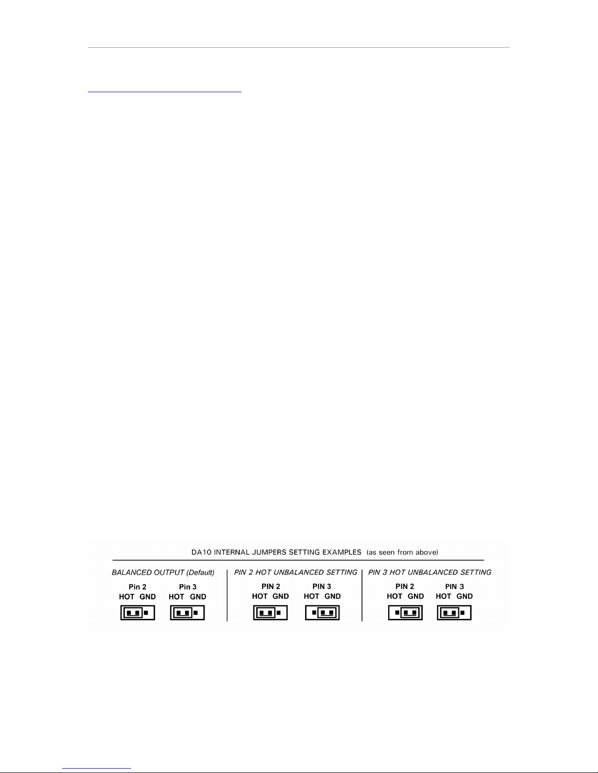
To set the jumpers for “Pin 3 Hot Unbalanced” operation:
11.) The jumpers that need to move are the ones labeled: “Hot, Pin 2, & Ground.” Pull the small
rectangular black plastic jumper straight “up” and off of the two pins it is on and re-position it to
slide back down on the two pins labeled “Pin 2” and “Ground.” Once you have done this for both
left and right XLR connector, you are done with this part.
12.) You are now ready to put the top cover back on the chassis. Pick up the chassis with your
thumb on the top edge of the rear panel, and your four fingers on the bottom of the chassis.
Carefully slide the chassis into the top cover and be sure the black and white power wires do not
get caught between them. As you slide the cover on, just as the top edge of the rear panel starts
to go inside the top cover, the switches and headphone jack start to come through the openings
in the front cover. Be gentle, and look to see that the switches are lining-up with their openings
before you slide the top cover all the way “on.”
13.) Place the DA10 bottom-side-up on the table, and replace the five Phillips head screws. They
don’t need to be very tight- just make sure they are “hand-tight.” In other words- don’t turn the
screw driver with too much more force than you would use to turn a door knob!
You are finished setting the jumpers.
Testing the DA10 for Unbalanced Operation-
Connect the appropriate cables, with the volume turned “down” on your preamp, or the AC power
turned “OFF” on your power amp or powered monitors. Turn the DA10’s power “ON” and set the
input and PLL settings, if you have not already done so. Turn “ON” the power amp or raise the
volume of the preamp to a normal level. Start playback of your source, and using the DA10’s level
control, raise the volume until you hear sound from your speakers. If you have turned the volume
setting up to at least “20,” and you still don’t hear any sound at all, try plugging headphones into
the DA10. If you hear sound in the headphones and not from the XLR output, reduce the volume
and check all the other switch settings and connections in your system. If everything seems to be
in order, and you hear sound in the headphones, but not from the XLR output, there is a
possibility that your adapters are wired for the opposite “Pin Hot” configuration from the way you
set the jumpers. This would ground the signal, resulting in “no sound.” The outputs are protected,
so operating the DA10 this way for a short time will not damage anything. Double check the
wiring of your adapters, and if you need to, open the DA10 and reset the jumpers correctly.
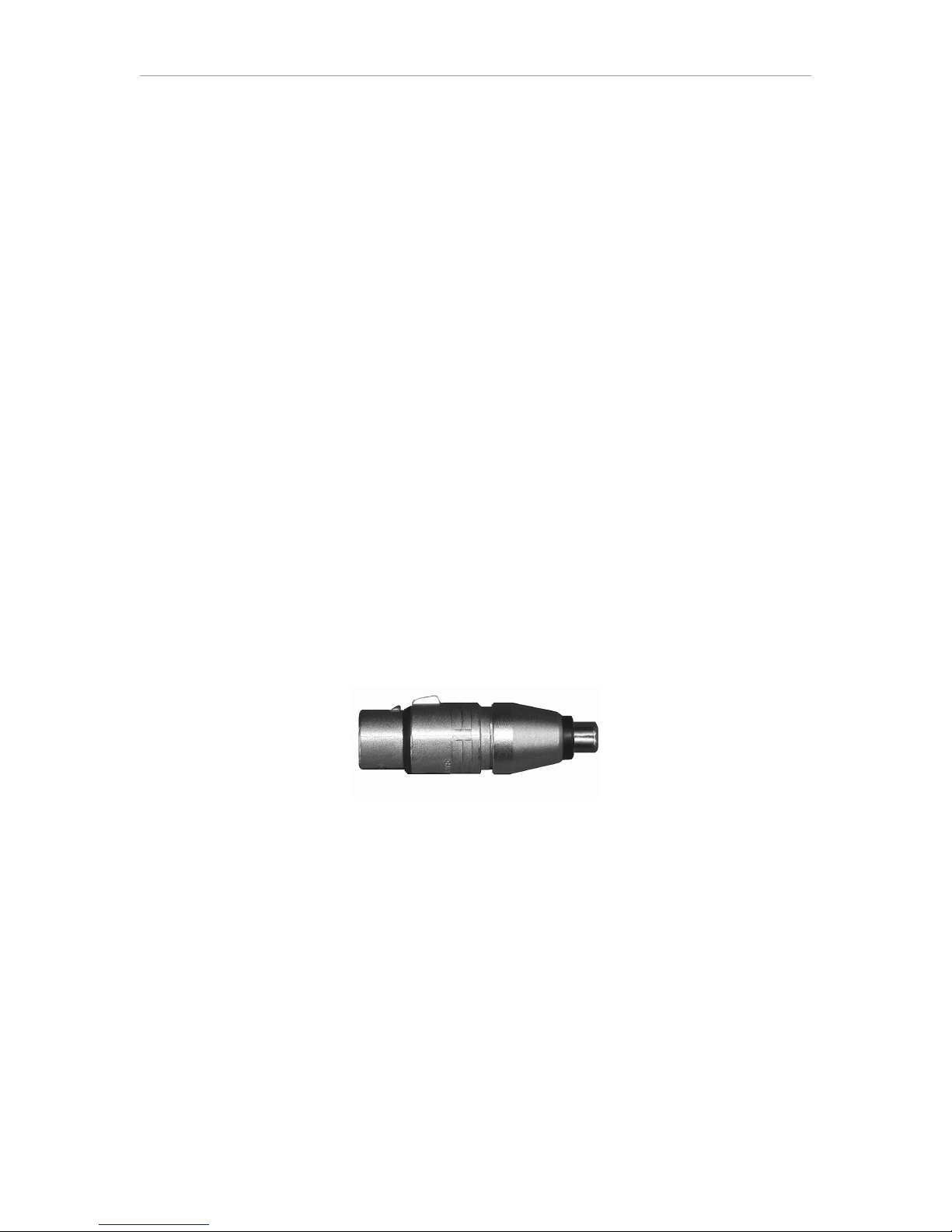
H. ALTERNATIVE WIRING FOR UNBALANCED CONNECTIONS
If custom cables are an option, properly wired custom cables can be used in a manner that allows
the internal jumpers to remain in the Balanced configuration when feeding unbalanced inputs.
This makes it possible to switch between feeding balanced inputs and unbalanced inputs without
having to open the DA10 and change the jumper settings.
Please note: Using this approach, it is very important that you use ONLY these special cables
when connecting the DA10 to unbalanced inputs!
- Alternative 1: Use PIN 3 for the “Hot” signal conductor, connect PIN 2 to nothing, and connect
Pin 1 as the signal’s “low” conductor. For e ample, with coa ial cable Pin 3 would connect to the
center conductor and Pin 1 would connect to the “shield.”
- Alternative 2: Use PIN 2 for the “Hot” signal conductor, connect PIN 3 to nothing, and connect
Pin 1 as the signal’s “low” conductor. For e ample, with coa ial cable Pin 2 would connect to the
center conductor and Pin 1 would connect to the “shield.”
In either case, when shielded twisted pair cable is used, the shield can be connected together
with the “low” signal conductor of the pair to Pin 1.

LavryBlack DA10 Specifications
9
SPECIFICATIONS:
THD+N at ma volume (volume = 56) – typical, 0.0008% FS, ma imum 0.0013% FS
Test conditions: 20Hz – 20KHz, -3dBFS sine wave, 22-22KHz BW
At all possible settings and switch combinations.
Dynamic Range: -110dB typical, -109 dB minimum
Test conditions: Non weighted
At all possible settings and switch combinations.
Drive Capability:
24dBu Balanced XLR output into 1K ohms at Volume = 56 or lower
21dBu Balanced XLR output into 600 ohms at Volume = 53 or lower
18dBu Unbalanced XLR output into 600 ohms at Volume = 56 or lower
18dBu Headphone into 100 ohms at Volume = 56 or lower
18dBu Headphone into 50 ohms at Volume = 50 or lower
Volume Control Precision:
Integral linearity (deviation from straight line) – better than 0.1dB
Differential linearity (step size) – better than 0.08dB
AC Power:
Voltage 90-264 VAC, Frequency 40-63Hz, Current 0.1A
Fuse Rating 2.5A “Time Delay” *
*Subject to change! Please always check the rating on the fuse and the one printed ne t to the
fuse holder on the power supply PC board before replacement. Replace the fuse ONLY with a
fuse of the same rating. If you have any questions, contact: techsupport@lavryengineering.com
Please Note: The DA10 automatically adjusts to AC power inputs in the range of 90 to 264 Volts
AC and line frequencies between 47 and 63 Hertz. There are no settings to change.
Weight and Dimensions:
8” wide 1.75” high 10.75” deep (with space for front panel switches and rear panel
connectors), < 5lbs. (shipping weight 6 lbs)

LavryBlack DA10 Warranty
10
L IM I TE D W A R R A N T Y – L AV R Y B L AC K S E RI E S MO D E L D A 10
Subject to the conditions set forth below, for one year after the ori inal purchase date of the
product, Lavry En ineerin will repair the product free of char e in the United States in the event
of a defect in materials or workmanship.
Lavry En ineerin may exchan e new or rebuilt parts for defective parts. Please call the factory
for an RMA number prior to shipment. No product will be accepted for warranty service without
a pre-issued RMA number.
This warranty is extended only to an ori inal purchaser of the product from Lavry En ineerin , or
an authorized reseller of Lavry En ineerin . Products that are purchased from unauthorized
resellers do not have any warranty covera e. A valid purchase receipt or other valid proof of
purchase will be required before warranty service is provided. This warranty only covers failures
due to defects in materials or workmanship and does not cover dama es which occur in shipment
or failures resultin from accident, misuse, line power sur es, mishandlin , maintenance,
alterations and modifications of the product, or service by an unauthorized service center or
personnel. Lavry En ineerin reserves the ri ht to deny warranty service to products that have
been used in rental, service bureau, or similar businesses.
This limited warranty ives you specific le al ri hts. You may have others which vary from
state/jurisdiction to state/jurisdiction.
LIMITS AND EXCLUSIONS
LAVRY ENGINEERING DOES NOT, BY VIRTUE OF THIS AGREEMENT, OR BY ANY
COURSE OF PERFORMANCE, COURSE OF DEALING, OR USAGE OF TRADE, MAKE
ANY OTHER WARRANTIES, EXPRESS OR IMPLIED, INCLUDING, WITHOUT
LIMITATION, ANY WARRANTY OF MERCHANTABILITY, FITNESS FOR A
PARTICULAR PURPOSE, TITLE OR NONINFRINGEMENT, AND ALL SUCH
WARRANTIES ARE HEREBY EXPRESSLY DISCLAIMED. LAVRY ENGINEERING
EXPRESSLY DISCLAIMS ANY IMPLIED INDEMNITIES. LAVRY ENGINEERING SHALL
NOT BE LIABLE FOR ANY INDIRECT, INCIDENTAL, CONSEQUENTIAL, PUNITIVE,
SPECIAL OR EXEMPLARY LOSSES OR DAMAGES, INCLUDING, WITHOUT
LIMITATION, DAMAGES TO RECORDINGS, TAPES OR DISKS, DAMAGES FOR LOSS
OF BUSINESS PROFITS, BUSINESS INTERRUPTION, LOSS OF BUSINESS
INFORMATION, LOSS OF GOODWILL, COVER, OR OTHER PECUNIARY LOSS,
ARISING OUT OF OR RELATING TO THE USE OF THE PRODUCT, OR ARISING FROM
BREACH OF WARRANTY OR CONTRACT, NEGLIGENCE, OR ANY OTHER LEGAL
THEORY, EVEN IF LAVRY ENGINEERING HAS BEEN ADVISED OF THE POSSIBILITY
OF SUCH LOSSES OR DAMAGES. ANY DAMAGES THAT Lavry ENGINEERING IS
REQUIRED TO PAY FOR ANY PURPOSE WHATSOEVER SHALL NOT EXCEED THE
ORIGINAL COST PAID TO LAVRY ENGINEERING FOR THE APPLICABLE PRODUCT.
BECAUSE SOME STATES/JURISDICTIONS DO NOT ALLOW THE EXCLUSION OR
LIMITATION OF LIABILITY FOR CONSEQUENTIAL OR INCIDENTAL DAMAGES, THE
FOREGOING LIMITATION MAY NOT APPLY TO YOU.
Other manuals for DA10
1
Table of contents
Other Lavry Media Converter manuals

Lavry
Lavry DA10 User manual

Lavry
Lavry DA924 User manual

Lavry
Lavry DA2002 User manual

Lavry
Lavry M AD-824 User manual

Lavry
Lavry AD11 User manual

Lavry
Lavry DA2002 User manual

Lavry
Lavry DA11 User manual

Lavry
Lavry AD122-96 Mark III User manual

Lavry
Lavry LavryBlack Series User manual

Lavry
Lavry LavryBlack Series User manual