roco PluX22 User manual

10881
PluX22 Digital-Lokdekoder
mit Lastregelung
PluX22 Digital Locomotive
Decoder
with load regulation
PluX22 Décodeur numérique
«traction»
(trois rails, courant alternatif) avec
compensation de charge
Inhaltsverzeichnis
Table of Contents
Table des matières
D
................................. 2 – 10
GB
................................. 12 – 20
F
................................. 22 – 30
8010881920 XI_2010.indd 1 03.12.2010 11:38:15

2
D
Eigenschaften des Empfängerbausteins auf einen Blick
Multiprotokollbetrieb möglich (Motorola** Digital, AC Analog, DCC Digital, DC Analog)
Vollautomatischer, fliegender Wechsel aller 4 Betriebsarten
Motorregelung
Motorfrequenz: 18,75 kHz
Unterstützung von Bremsstrecken
14 Fahrstufen bei Motorola**-Betrieb, 14, 27, 28 oder 128 Fahrstufen bei DCC-Betrieb
Lokadressen programmierbar
NMRA-kompatibel
Komfortable Änderung der Betriebsparameter möglich: die Lok muss nicht geöffnet werden
Richtungsabhängige Beleuchtung
Rangiergang (Halbierung aller Geschwindigkeiten) mit der Taste F8 schaltbar
Aus/Einschalten der Beschleunigungs- und Bremszeiten mit der Taste F7
Überstromgeschützt
7 zusätzliche Funktionsausgänge
(z.B. Rücklicht, Fernlicht, Innenbeleuchtung, Rauchgenerator, elektrische Kupplung)
Betrieb der Lokomotive
Der Decoder kann in Fahrzeugen mit Schnittstelle PluX22 eingesetzt werden. Er kann auf digitalen und konven-
tionellen (analogen) 2-Leiter- oder- Mittelleiteranlagen eingesetzt werden. Auf konventionellen Anlagen sind die
Zusatzfunktionen naturgemäß eingeschränkt. Der Decoder hat die besondere Fähigkeit, das System automatisch
zu erkennen. Im Digitalbetrieb haben die Decoder die Adresse 3.
Analogbetrieb
Im Analogbetrieb verhält sich der Decoder wie ein konventioneller Fahrtrichtungsumschalter.
Digital-Betrieb
DCC-Betrieb:
Betrieb des Fahrzeugs ist mit jedem DCC-konformen System möglich.
Das Fahrzeug kann auf DELTA- oder Mittelleiter-Digitalanlagen (Motorola**/DCC) eingesetzt werden.
Taste F8 des Steuergeräts schaltet den Rangiergang (Halbierung aller Geschwindigkeiten) ein bzw. aus. Taste F7
des Steuergeräts schaltet die eingestellten Verzögerungen für Anfahren und Bremsen aus und ein.
Motorola**-Betrieb
Das Fahrzeug kann mit allen Motorola**-Systemen bzw. kompatiblen Systemen verwendet werden. Die
Funktionen F1 bis F4 können allerdings nur mit dem sog. „Neuen Motorola**-Format“ benutzt werden. Um
dieses zu aktivieren, müssen an der Central Unit 6021 die DIP-Schalter 1 und 2 auf die obere Position („On“)
gestellt werden.
DELTA-Betrieb
Der Fahrzeugdecoder ist werksseitig auf die Adresse 03 voreingestellt, daher muss das Fahrzeug für den Betrieb
mit dem DELTA-Steuergerät auf ein entsprechendes Fahrzeugsymbol der zugeordneten Adressen umprogram-
miert werden.
Diese Adressen sind: Dampflok: 78
Diesellok: 72
E-Lok: 24
Triebzug: 60
Delta Pilot: 80
Besitzer des DELTA-Systems haben das Problem, dass dort keine Lichttaste zur Verfügung steht. Das Fahrzeug
kann jedoch so umgestellt werden, dass die Lichter stets leuchten (natürlich abhängig von der Fahrtrichtung).
Voraussetzung dafür ist, dass beispielsweise mit der Central Unit 6021 der Wert in CV 51 um 8 erhöht wird.
8010881920 XI_2010.indd 2 03.12.2010 11:38:15

3
D
Betriebsparameter
Programmieranleitung für Märklin* 6020/6021
Das Fahrzeug kennt viele Betriebsparameter. Alle Parameter sind in sog. CVs (Configuration Variables) abgespei-
chert. Diese können gezielt verändert werden, abhängig von der verwendeten Steuerzentrale. Eine Auflistung der
CVs finden Sie am Ende dieser Anleitung.
Mit einer Märklin* Zentrale können alle CV’s programmiert, aber nicht ausgelesen werden.
Der Fahrregler muss auf „0“ stehen.
Ausser der zu programmierenden Lokomotive darf sich keine weitere Lok auf den Gleisen befinden!
Beachten Sie beim Programmieren die Blinksignale der Lokbeleuchtung.
Solange sich der Decoder im Programmiermodus befindet, können beliebig viele
Änderungen/ Einstellungen vorgenommen werden.
1. STOP und GO Taste gleichzeitig drücken, bis ein Reset ausgeführt wird
2. STOP Taste zum Abschalten der Schienenspannung
3. Adresse 80 eingeben
4. Fahrtrichtungsumschalter drücken und gedrückt halten, dann zusätzlich GO für mind. 0,5 sek.
drücken, um Schienenspannung wieder einzuschalten
5. Dekoder ist im Programmiermodus = Langsames Blinken
6. Eingabe des zu ändernden Registers (zweistellig im Adressfeld)
7. Zur Bestätigung Fahrtrichtungsumschalter drücken = Schnelles Blinken
8. Gewünschten Wert eingeben (zweistellig im Adressfeld)
9. Zur Bestätigung Fahrtrichtungsumschalter drücken = Langsames Blinken
Falls weitere CV’s programmiert werden sollen, Punkt 5-9 wiederholen.
Wenn die Programmierung beendet werden soll, die Zentrale auf „STOP“ schalten oder die Adresse „80“ einge-
ben und kurz die Fahrtrichtungsumschaltung betätigen.
Da bei der Programmierung mit einer Motorola** Digitalzentrale von Märklin* nur Eingaben von 01 bis 80
möglich sind, muss der Wert „0“ über die Adresse als „80“ eingegeben werden.
Programmieranleitung für Märklin* „Mobile Station“
Um die Parameter des Decoders mit der „Mobile Station“ umzuprgrammieren ist es notwendig, eine Lok aus
der Datenbank anzulegen, welche den Programmiervorgang unterstützt.
Anlegen der Lok „EE 3/3“:
1. ESC-Taste drücken
2. Menüpunkt „Neue Lok“ auswählen
3. Menüpunkt „Datenbank“ auswählen
4. Mit dem Drehknopf die Artikelnummer „36330“ auswählen
5. Die Lok mit dem Namen „EE 3/3“ wird angelegt und erscheint am Display
Programmieren mit Märklin* Mobile Station:
1. „ESC“ -Taste drücken
2. Drehregler zum Menüpunkt „LOK ÄNDERN“ nach rechts drehen
3. Drehregler zum Menüpunkt „REG“ 2x nach links drehen
4. Drehregler drehen bis die gewünschte CV-Adresse blinkt
5. Drehregler drehen bis der gewünschte CV-Wert blinkt
Der Decoder bestätigt das Programmieren mit einer kurzen Bewegung am Motor.
8010881920 XI_2010.indd 3 03.12.2010 11:38:15

4
D
4
Page-Register zur Eingabe von CV-Nummern größer 79
CV-Adressen größer als 79 können nur mit Hilfe des Page-Registers programmiert werden. Dieses Page-
Register ist die CV 66. Wird die CV 66 mit einem Wert größer 0 beschrieben, so wird bei allen nachfolgenden
Programmiervorgängen der Inhalt der CV 66 mal 64 zu jedem folgenden eingegebenen Adresswert hinzuaddiert.
Der eingegebene Wert muss im Bereich 1 bis 64 liegen.
Das Page-Register (CV 66) muss wieder auf 0 gesetzt werden, wenn eine der niedrigen CVs
geändert werden soll.
Beispiel:
Soll die CV 82 mit dem Wert 15 programmiert werden, so muss zuerst die CV 66 mit dem Wert 1 programmiert
werden. Anschließend kann die CV 18 (64 + 18 = 82) mit dem Wert 15 programmiert werden. Im Decoder wird
jetzt der Wert 15 in der CV Adresse 82 abgelegt, die sich aus der Addition des Inhalts der CV 66 (im Beispiel: 1)
multipliziert mit 64 (also 64) und der eingegebenen CV Adresse an der Zentrale (18) ergibt.
Offset-Register zur Eingabe von CV-Werten größer 79
CV-Werte größer als 79 können nur mit Hilfe des Offset-Registers programmiert werden. Dieses Offset-Register ist die
CV 65. Wird die CV 65 mit einem Wert größer 0 beschrieben, so wird bei allen nachfolgenden Programmiervorgängen
der Inhalt der CV 65 mit 4 multipliziert und zu jedem im Folgenden programmierten CV-Wert hinzuaddiert und in der
entsprechenden CV abgelegt.
Das Offset-Register (CV 65) muss wieder auf 0 gesetzt werden, wenn wieder ein Wert kleiner als
80 programmiert werden soll.
Beispiel:
Soll die CV 49 mit dem Wert 157 programmiert werden, so muss zuerst die CV 65 mit dem Wert 25 programmiert
werden. Anschließend kann die CV 49 mit dem Wert 57 programmiert werden. Im Decoder wird jetzt der Wert
4 x 25 + 57 abgelegt.
Hinweis: Bei der Programmierung der CV 65 und der CV 66 bleibt der Inhalt von Offset- und Page-Register
unberücksichtigt.
Parameteränderung mit DCC-Systemen
Mit einen DCC-kompatiblen Digitalsystem können die CVs sehr einfach und Komfortabel verändert werden.
Bitte lesen Sie hierzu das entsprechende Kapitel (etwa: Programmierung von DCC-Decodern) in Ihrem Handbuch.
Der Decoder kennt alle Programmiermethoden der NMRA.
CV-Einstellungen
Das Verhalten des Decoders kann mithilfe der CVs (CV= Configuration Variable) sehr individuell auf die
Erfordernisse bzw. Fähigkeiten der Lok eingestellt werden.
Decoder Reset
Sie können jederzeit die Werkseinstellungen wiederherstellen, wenn Sie einmal nicht mehr weiter wissen:
Programmieren Sie dazu in CV 8 den Wert 08.
Bremsstrecken
In den Digitalsystemen gibt es automatische Bremsstrecken. Bei diesem Fahrzeug ist die Unterstützung von
Bremsstrecken ausgeschaltet. Dies geschieht mit Hilfe von CV 49.
Märklin* Bremsstrecke
Der Decoder reagiert auf eine Märklin*-Bremsstrecke (Bremsen mit einer analogen Spannung am Gleis), wenn
CV 29 Bit 2 und CV 49 Bit 7 gesetzt werden (Werkseinstellung 1 und 0).
8010881920 XI_2010.indd 4 03.12.2010 11:38:15

5
D
CV Name Beschreibung Werte-
bereich
Werks-
wert
1 Lokadresse Adresse der Lok (Motorola**) DCC
01 – 127
Motorola **
01 – 80
3
2 Anfahrspannung Legt die Mindestgeschwindigkeit der Lok fest 01 – 63 5
3 Beschleunigungszeit Je größer dieser Wert, umso mehr Zeit braucht
die Lok zum Beschleunigen
01 – 63 1
4 Bremsverzögerung Je größer dieser Wert, umso mehr Zeit braucht
die Lok zum Abbremsen
01 – 63 3
5 Maximalspannung legt die Höchstgeschwindigkeit der Lok fest 01 – 63 60
6 Mittenspannung legt die Geschwindigkeit der Lok bei mittlerer
Fahrstufe fest
01 – 63 32
7 Versionsnummer Interne Softwareversion des Decoders (nur
lesen)
------- -------
8 Hersteller ID NMRA-Identifikationsnummer des
Herstellers Uhlenbrock.
08 (Reset) 85
12 Digitalformat Über diese CV kann eingestellt werden, welches
Digitalformat aktiv erkannt werden soll.
Kein Digitalformat erkennen Wert: 0
DCC-Format ein Wert: 1
Motorola**-Format Wert: 2
00 – 03 3
17 Lange Adresse Höherwertiges Byte 192 – 231 192
18 Lange Adresse Niederwertiges Byte 0 – 255 0
29 Konfigurations-
register
Diverse Einstellungen der Lok, nur relevant im
DCC-Betrieb. Addieren Sie Werte der einzelnen
Funktionen, um den Wert der CV29 zu bestimmen.
Bsp.: 28 Fahrstufen + Analogbetrieb
erlauben = 2 + 4 = 6.
00 – 255 6
Bit Funktion Wert
0 Normale Fahrtrichtung
Umgekehrtes Richtungsverhalten
0
1
1 14 Fahrstufen im DCC-System
28 / 128 Fahrstufen im DCC-System
0
2
2 Analogbetrieb ausschalten
Analogbetrieb erlauben
0
4
4 3-Punkt-Kennlinie gemäß
CV2, CV5, CV6
28-Punkt-Kennlinie gemäß
CV67 - CV94
0
16
5 Kurze Adresse (CV1) im DCC-Betrieb
Lange Adresse (CV17+18) im DCC-
Betrieb verwenden
0
32
CV-Liste
8010881920 XI_2010.indd 5 03.12.2010 11:38:16

6
D
CV Name Beschreibung Werte-
bereich
Werks-
wert
47 Geschwindigkeits-
korrektur
Geschwindigkeitskorrektur vorwärts
Korrekturfaktor = Wert aus CV64/128
00 – 63 32
48 Geschwindigkeits-
korrektur
Geschwindigkeitskorrektur rückwärts
Korrekturfaktor = Wert aus CV64/128
00 – 63 32
49 Erweiterte
Kofiguration
Hier können Sie die Unterstützung für
Bremsstrecken aktivieren oder die Lastregelung
abschalten
00 – 255 32
51 Analoge
Betriebsart
Einstellung der analogen Betriebsart 01 – 03 3
59 Reset
(alternatve zu CV8)
Reset auf Werkseinstellung
Wird diese CV auf 1 programmiert, so wird der
Decoder auf seine Werkseinstellungen zurück-
gesetzt
0,1 0
64 Bremsstrecken Geschwindigkeit am Ende der Bremsstrecke
Gültig wenn CV49 Bit2=1 u. Bit7=1
00 – 63 30
65 Offset-Register Offset-Register für die CV-Progr. mit
Motorolazentrale
00 – 255 0
66 Page-Register Page-Register für die CV-Progr. mit
Motorolazentrale
00 – 255 0
67-
94
Kennlinie Kennlinie für die Fahrtstufen 1-28 00 – 255 aufsteigende
unterschiedl.
Werte
Bit Beschreibung Wert
0 AC-Erkennung aus
AC-Erkennung ein
0
1
1 DC-Erkennung aus
DC-Erkennung ein
0
2
3 Beleuchtung schaltbar
Beleuchtung permanent
0
8
Bit Beschreibung Wert
0 Lastregelung aktiv
Lastregelung aus
0
1
2 Bremsen bis auf 0 im Bremsabschnitt
Bremsen bis auf Fahrstufe gemäß CV52
0
4
5 EMK-Anpassung aus
EMK-Anpassung ein
0
32
6 Lichtanschlüsse nicht tauschen
(vorne/hinten)
Lichtanschlüsse tauschen
0
64
7 Bremsen nur mit Bremssignal
Bremsen mit analoger Spannung
0
128
8010881920 XI_2010.indd 6 03.12.2010 11:38:16

7
D
Weitere, besondere Funktionen des Decoders, die über CVs eingestellt werden können
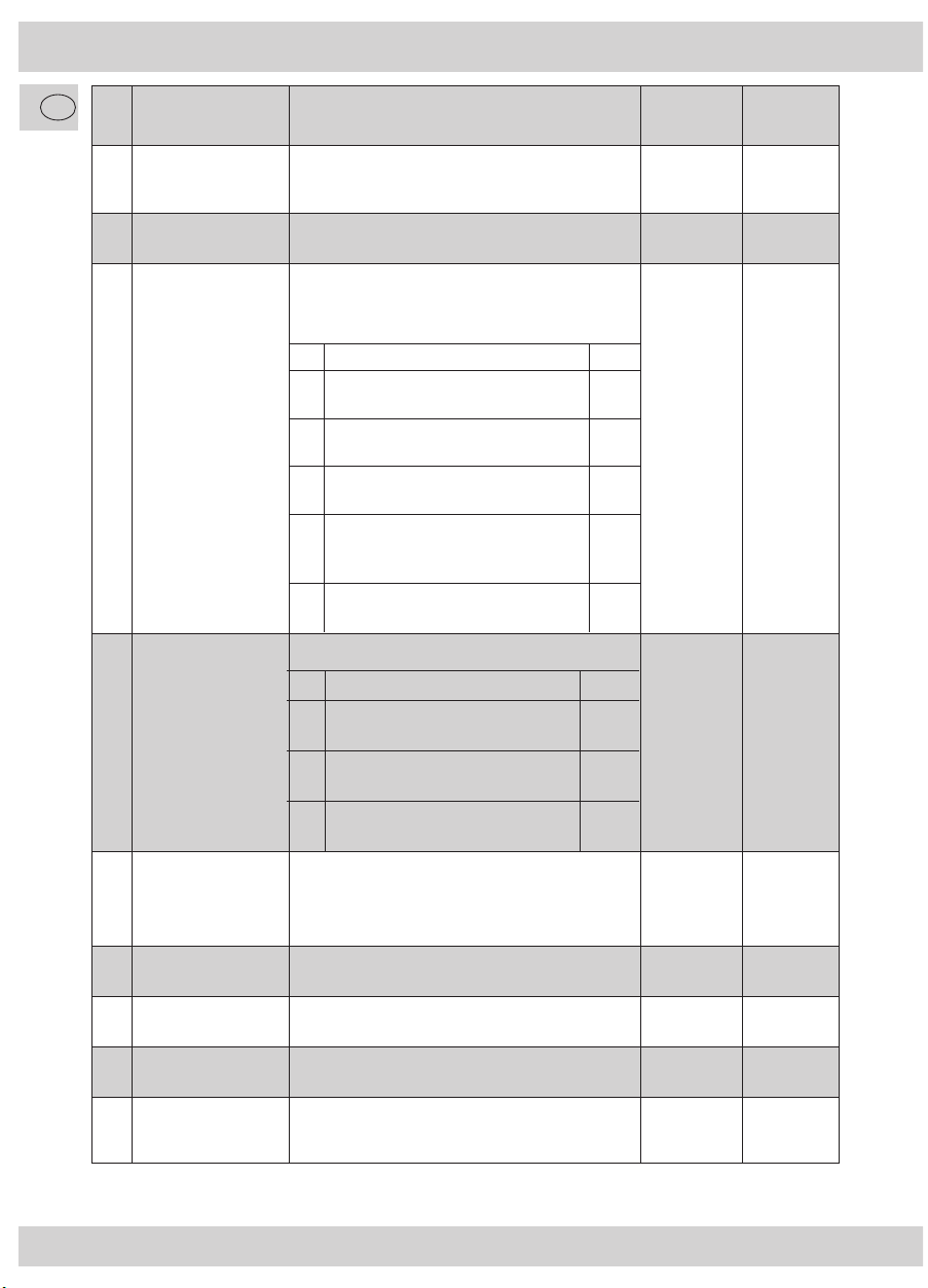
Function Mapping
Der PluX22-Decoder verfügt über 2 Anschlüsse für weißes Stirnlicht, 7 AUX-Anschlusse für weitere elektrische
Verbraucher sowie Betriebsfunktionen Rangiergang (RG) und Abschalten der Verzögerungen (VZ). Welche
Funktion mit welcher Funktionstaste Ihres Steuergerätes geschaltet werden kann, ist der sog. Tabelle für
Function Mapping zu entnehmen.
CV Taste VZ RG AUX7 AUX6 AUX5 AUX4 AUX3 AUX2 AUX1 Licht
hinten
Licht
vorn
Wert
33 F0v 128 64 32 16 8 4 2 11
34 F0r 128 64 32 16 8 4 21 2
35 F1 128 64 32 16 8 42 1 4
36 F2 128 64 32 16 84 2 1 8
37 F3 128 64 32 16 8 4 2 1 16
38 F4 128 64 32 16 8 42 1 4
39 F5 128 64 32 16 84 2 1 8
40 F6 128 64 32 16 8 4 2 1 16
41 F7 128 64 32 16 8 4 2 1 128
42 F8 128 64 32 16 8 4 2 1 64
43 F9 128 64 32 16 8 4 2 1 32
44 F10 128 64 32 16 8 4 2 1 0
45 F11 128 64 32 16 8 4 2 1 0
46 F12 128 64 32 16 8 4 2 1 0
Die in der Tabelle fett markierten Zahlen geben die Werkseinstellungen wieder, die Sie auch in der rechten
Spalte wiederfinden. Durch Ändern der Werte in den CVs können Sie die Zuordnungen Ihren Wünschen
entsprechend einstellen. Beispiele: Mit CV40=64 wird mit F6 nicht mehr AUX6, sondern der Rangiergang
geschaltet. Mit CV38=6 (also 4+2) werden AUX3 und AUX4 gemeinsam mit F4 geschaltet.
Welche elektrischen Verbraucher wo angeschlossen sind, entnehmen Sie bitte den Unterlagen zu Ihrer Lok.
Wird eine Lok ab Werk mit diesem Decoder ausgeliefert, kann ein individuelles Function Mapping vorliegen,
das sich von obiger Tabelle unterscheidet.
Achtung: in den grau markierten Bereichen lassen sich keine Zuordnungen vornehmen.
Zugseitige Lichtabschaltung
Die weiße Stirnbeleuchtung Ihrer Lok ist an die Ausgänge „Licht vorn“ bzw. „Licht hinten“ angeschlos-
sen. Dies sind die Anschlüsse, die das Licht automatisch mit der Fahrtrichtung umschalten. Auch eventuell
vorhandene rote Schlussleuchten sind bei Loks mit 6- oder 8-poliger Schnittstelle in der Regel an diesen
Ausgängen angeschlossen, weiß und rot funktionieren also gemeinsam.
Bei Loks mit PluX-Schnittstelle können die roten Schlussleuchten auch an anderen Ausgängen angeschlos-
sen sein, damit sie gezielt ein- oder ausgeschaltet werden können, z.B. wenn die Lok ohne oder mit Zug
fährt.
Dieser PluX22-Decoder verfügt nun über die Fähigkeit, rote Schlusslampen an beliebigen Anschlüssen
AUX1-AUX7 in den Stirnlichtwechsel einzubinden und dazu noch das Stirnlicht, ob weiß oder rot, auf der
Seite eines angehängten Zuges vorbildgerecht automatisch komplett abzuschalten. Hierzu dienen die CVs
107 und 108.
8010881920 XI_2010.indd 7 03.12.2010 11:38:16

8
D
CV Name Beschreibung Werte-
bereich
Werks-
wert
107 Licht aus
(Zug vorne)
Multiplizieren Sie die AUX-Anschlussnummer 1-7 des vor-
deren roten Lichts mit 16 und addieren sie die Nummer
1-12 der Funktionstaste, mit der das Licht vorn ausge-
schaltet werden soll:
Beispiel: rotes Licht an AUX2, Licht vorn abschalten
mit F1: Wert=2x16+1=33
Der Wert 0 schaltet diese Funktion aus.
0 − 144 0
108 Licht aus
(Zug hinten)
Multiplizieren Sie die AUX-Anschlussnummer 1-7 des hin-
teren roten Lichts mit 16 und addieren sie die Nummer
1-12 der Funktionstaste, mit der das Licht hinten ausge-
schaltet werden soll:
Beispiel: rotes Licht an AUX1, Licht hinten
abschalten mit F2: Wert=1x16+2=18
Der Wert 0 schaltet diese Funktion aus.
0 − 144 0
Soll nur das weiße Licht automatisch abgeschaltet werden, ist der entsprechende AUX-Wert 0.
Achtung: In die CVs, die gemäß Function Mapping den entsprechenden AUX-Anschlüssen zugeordnet sind,
ist jeweils 0 zu programmieren, um Mehrdeutigkeiten zu vermeiden.
Blinkgenerator
Alle an die AUX-Anschlüsse angeschlossenen Funktionen, aber auch die Stirnlampen, können mit einer
einheitlich einstellbaren Blinkfunktion versehen werden.
CV Name Beschreibung Werte-
bereich
Werks-
wert
109 Funktions-
Auswahl
Mit jedem der 8 Bits kann ein Funktionsanschluss ausge-
wählt werden, der blinken soll:
Bit 0 Stirnlicht Wert: 1
Bit 1 AUX 1 Wert: 2
Bit 2 AUX 2 Wert: 4
Bit 3 AUX 3 Wert: 8
Bit 4 AUX 4 Wert: 16
Bit 5 AUX 5 Wert: 32
Bit 6 AUX 6 Wert: 64
Bit 7 AUX 7 Wert: 128
Sollen mehrere Funkionen blinken, sind die entsprechen-
den Werte zu addieren.
0 − 255 0
110 Aus-Zeit Einstellbar in X Stufen zu je 0,1s, also von 0-25,5s 0 − 255 10
111 Ein-Zeit Einstellbar in X Stufen zu je 0,1s, also von 0-25,5s 0 − 255 2
8010881920 XI_2010.indd 8 03.12.2010 11:38:16

9
D
CV Name Beschreibung Werte-
bereich
Werks-
wert
116 F0-Dimmen Dimmen von 0% (Wert 0) bis 100% (Wert 32) 0 − 32 32
117 AUX1-Dimmen Dimmen von 0% (Wert 0) bis 100% (Wert 32) 0 − 32 32
118 AUX2-Dimmen Dimmen von 0% (Wert 0) bis 100% (Wert 32) 0 − 32 32
119 AUX3-Dimmen Dimmen von 0% (Wert 0) bis 100% (Wert 32) 0 − 32 32
120 AUX4-Dimmen Dimmen von 0% (Wert 0) bis 100% (Wert 32) 0 − 32 32
121 AUX5-Dimmen Dimmen von 0% (Wert 0) bis 100% (Wert 32) 0 − 32 32
122 AUX6-Dimmen Dimmen von 0% (Wert 0) bis 100% (Wert 32) 0 − 32 32
123 AUX7-Dimmen Dimmen von 0% (Wert 0) bis 100% (Wert 32) 0 − 32 32
Dimmen der Funktionsausgänge
Die Helligkeit bzw. die Spannung an jedem Funktionsausgang Stirnlicht bzw. AUX1-7 kann individuell
gedimmt werden.
Elektrische Kupplung (Optional)
Für ein sicheres Entkuppeln können Spannungspegel und Schaltzeiten in weiten Bereichen eingestellt
werden. Die elektrischen Kupplungen müssen hierzu an den Anschlüssen AUX1 bzw. AUX2 angeschlossen
sein.
CV Name Beschreibung Werte-
bereich
Werks-
wert
124 Kuppel-
Wiederholung
Anzahl der sich automatisch wiederholenden Entkupp-
lungs-Vorgänge
0 − 255 0
125 Einschalt-
Dimmen
Die Spannung zum Anziehen der Entkuppler-Spule kann
in 255 Stufen gedimmt werden
0 − 255 255
126 Halte-
Dimmen
Die Spannung zum Halten der Kupplung kann in 255
Stufen gedimmt werden
0 − 255 64
127 Ein-Zeit Die Zeit zum Anziehen der Kupplung kann in 255 Stufen
zu je 50ms eingestellt werden
0 − 255 5
128 Halte-Zeit Die Zeit zum Halten der geöffneten Kupplung kann in 255
Stufen zu je 100ms eingestellt werden
0 − 255 20
129 Pausenzeit Die Pause zwischen automatisch wiederholten Ent-
kupplungsvorgängen kann in 255 Stufen zu je 100ms
eingestellt werden
0 − 255 20
8010881920 XI_2010.indd 9 03.12.2010 11:38:16

10
D
* Märklin ist ein eingetragenes Warenzeichen der Gebr. Märklin & Cie. GmbH, Göppingen
** Motorola ist eine eingetragenes Warenzeichen der Motorola Inc., Tempe-Phoenix/Arizona (USA)
Technische Daten
Adressen: 1– 9999 (Lange DCC Adresse)
Max. Motorstrom / Gesamtbelastung: 1 A
Funktionsausgänge (einzeln und in Summe): je 0,5A
Größe: 22,0 x 15,0 x 3,8 mm
Der Decoder ist voreingestellt auf die Adresse 03, einen Betrieb mit 28 Fahrstufen und kann im
DCC- und Motorola**-Datenformat gefahren und programmiert werden.
Rauchgenerator (Optional)
Der Rauch aus dem Schlot einer Dampflok ist nie konstant. Je nach Betriebssituation ist er unterschiedlich
stark. Mit nachfolgenden CVs kann die Rauchentwicklung in weiten Bereichen eingestellt werden. Dabei
muss der Rauchentwickler an den Ausgängen AUX1 oder AUX2 angeschlossen sein.
CV Name Beschreibung Werte-
bereich
Werks-
wert
130 Definitionen Mit den Bits 0 bis 5 kann eine „Anfahrzeit“ in Schritten
von 0,2s eingestellt werden:
Bit 0 Anfahrzeit Wert: 1
Bit 1 Anfahrzeit Wert: 2
Bit 2 Anfahrzeit Wert: 4
Bit 3 Anfahrzeit Wert: 8
Bit 4 Anfahrzeit Wert: 16
Bit 5 Anfahrzeit Wert: 32
Bit 6 Generator an AUX2 Wert: 64
Bit 7 Generator an AUX1 Wert: 128
Die entsprechenden Werte zu addieren.
0 − 255 0
131 Anfahren Die Energie beim Anfahren der Lok in der Zeit gemäß
CV130 kann in Stufen eingestellt werden
31
132 Normalbetrieb Die Energie bei normal fahrender Lok kann in Stufen
eingestellt werden
16
133 Stillstand Die Energie bei Stillstand der Lok kann in Stufen einge-
stellt werden.
8
8010881920 XI_2010.indd 10 03.12.2010 11:38:17

11
GB
8010881920 XI_2010.indd 11 03.12.2010 11:38:17

12
GB
Receiver Module Features at a Glance
Multiprotocol operation possible (Motorola** Digital, AC Analogue, DCC Digital, DC Analogue)
Fully-automatic flying change between all 4 operating modes
Engine control
Engine frequency: 18.75 kHz
Support of braking distances
14 driving stages in Motorola** operation and 14, 27, 28 or 128 driving stages in DCC operation
Programmable locomotive addresses
NMRA-compatible
The operating parameters can be comfortably changed: the locomotive does not have to be opened
Direction-related lighting
Shunting (all speeds reduced by half) switchable with the F8 key
Activation/deactivation of the accelerating and braking times with the F7 key
Overload protection
7 additional function output
(e.g. rear light, full beam, interior lighting, smoke generator, electrical coupling)
Locomotive Operation
The decoder can be installed in vehicles with a PluX22 interface. It can be used with both digital and con-
ventional (analogue) 2-conductor systems or with middle conductor systems. The additional functions are
obviously restricted on conventional systems. The decoder has the special ability of being able to automati-
cally detect the system. The decoder has the address 3 in digital operation.
Analogue operation
In analogue operation, the decoder acts as a conventional direction of travel commutator.
Digital operation
DCC operation: the vehicle can be operated with all DCC-conform systems.
The vehicle can be used with DELTA systems or digital middle conductor systems (Motorola**/DCC).
The F8 key of the control device activates and deactivates the shunting (the reduction of all speeds by half).
The F7 key on the control device activates and deactivates the set delays for start-up and braking.
Motorola** operation
The vehicle can be used with all Motorola** and compatible systems. The functions F1 to F4 can only be
used with the so-called “new Motorola ** format“ however. In order to activate these, the DIP switches 1
and 2 on the Central Unit 6021 have to be set to the top position (“On“).
DELTA operation
The vehicle decoder has been preset to the address 03 by the manufacturer so that the vehicle has to be
reprogrammed to a corresponding vehicle symbol for the allocated addresses before a Delta operation is
possible.
These addresses are: Steam locomotive: 78
Diesel locomotive: 72
E-locomotive: 24
Multiple unit: 60
Delta Pilot: 80
Owners of the DELTA system have the problem that it does not have a light switch. The vehicle can be so
altered however that the lights remain on (obviously in relation to the direction of travel). The requirement
for this is that the Central Unit 6021 THE CV 51 value is increased by 8.
8010881920 XI_2010.indd 12 03.12.2010 11:38:17

13
GB
Operating Parameters
Programming instructions for the Märklin* 6020/6021
The vehicle is able to detect numerous operating parameters. All of the parameters are stored in so-called
CVs (Configuration Variables). These can be altered in a targeted manner, depending on the control centre
which is used. You will find a list of the CVs at the end of these instructions.
A Märklin* centre can be used to program all of the CVs but they cannot be read out.
The controller has to be set to “0“.
No locomotives are to be on the tracks except the one which is to be programmed!
Please observe the locomotive lighting flashing signals during programming.
Any number of changes/settings can be made as long as the decoder is in programming mode.
1. Press the STOP and GO buttons at the same time until a reset is carried out
2. STOP button until deactivation of the track voltage
3. Enter address 80
4. Press the direction of travel switch and keep it pressed in and then additionally press GO for at
least 0.5 sec in order to reactivate the track voltage
5. The decoder is in programming mode = slow flashing
6. Enter the register which is to be changed (two figures in the address field)
7. Confirm by pressing the direction of travel switch = rapid flashing
8. Enter the required value (two figures in the address field)
9. Confirm by pressing the direction of travel switch = slow flashing
If you wish to program additional CVs, repeat numbers 5.-9.
To stop the programming, switch the centre to “STOP“ or enter the address “80“ and briefly activate the
direction of travel change.
As a Motorola** Digital Centre from Märklin* can only be programmed by entering numbers between 01
and 80, the value “0“ has to be entered via the address as “80“.
Programming instructions for the Märklin* “Mobile Station“
In order to reprogram the decoder parameters with the “Mobile Station“, a locomotive from the database has
to be created which supports the programming process.
Creating locomotive “EE 3/3“:
1. Press the ESC button
2. Select the menu item “New Loc“
3. Select the menu item “Database“
4. Select the article number “36330“ with the rotary knob
5. The locomotive with the name “EE 3/3“ is created and displayed
Programming with the Märklin* Mobile Station:
1. Press the “ESC“ button
2. Turn the rotary controller to the right until you reach menu item “CHANGE LOC“
3. Turn the rotary controller 2x to the left until you reach menu item “REG“
4. Turn the rotary controller until the required CV address flashes
5. Turn the rotary controller until the required CV value flashes
The decoder confirms the programming with a slight movement at the engine.
8010881920 XI_2010.indd 13 03.12.2010 11:38:17

14
GB
Page register for entering CV numbers which are greater than 79
CV addresses which are greater than 79 can only be programmed with the assistance of the page register. This
page register is the CV 66. If a value which is greater than 0 should be entered in the CV 66, the content of the
CV 66 will be multiplied by 64 and added to each of the following address values which are entered during all
of the subsequent programming processes. The entered value is to be between 1 and 64.
The page register (CV 66) has to be reset to 0 if one of the lower CVs is to be changed.
Example:
If the CV 82 is to be programmed with the value 15, the CV 66 has to be initially programmed with the value 1.
The CV 18 (64 + 18 = 82) can then be programmed with the value 15. The value 15 is now stored in CV address
82 in the decoder, this resulting from the content of the CV 66 (in the example: 1) multiplied by 64 (therefore 64)
and the CV address entered in the centre (18).
Offset register for entering CV values greater than 79
CV values which are greater than 79 can only be programmed with the assistance of the offset register. This offset
register is the CV 65. If a value greater than 0 is entered in the CV 65, the content of the CV 65 will be multiplied by
4 and added to each of the following programmed CV values before being stored in the corresponding CV.
The offset register (CV 65) has to be reset to 0 if a value lower than 80 is to be programmed.
Example:
If the CV 49 is to be programmed with the value 157, CV 65 has to be initially programmed with the value 25, fol-
lowed by the CV 49 being programmed with the value 57. The value 4 x 25 + 57 is now stored in the decoder.
Note: The contents of the offset register and page register are not taken into account when programming
the CV 65 and CV 66.
Changing parameters with DCC systems
The CVs can be very easily and comfortably changed when using a DCC-compatible digital system. Please refer
to the appropriate chapter (e.g. programming of DCC decoders) in your manual. The decoder is aware of all of
the NMRA programming methods.
CV settings
The reaction of the decoder can be customised to the requirements and capabilities of the locomotive with the
assistance of the CVs (CV= Configuration Variable).
Decoder Reset
Should you not know what to do at any time, you can restore the works settings at all times: simply program
the value 08 in the CV 8.
Braking distances
Digital systems have integrated automatic braking distances. The supporting of braking distances is deactivated
in this vehicle. This is carried out with the assistance of the CV 49.
Märklin* Bremsstrecke
Der Decoder reagiert auf eine Märklin*-Bremsstrecke (Bremsen mit einer analogen Spannung am Gleis), wenn
CV 29 Bit 2 und CV 49 Bit 7 gesetzt werden (Werkseinstellung 1 und 0).
8010881920 XI_2010.indd 14 03.12.2010 11:38:17

15
GB
CV Name Description Value
Range
Works
Value
1 Locomotive address Address of the locomotive (Motorola**) DCC
01 – 127
Motorola **
01 – 80
3
2 Start-up voltage Determines the slowest locomotive speed 01 – 63 5
3 Acceleration time The higher this value, the more time the loco-
motive takes to accelerate
01 – 63 1
4 Braking deceleration The higher this value, the more time the loco-
motive takes to brake
01 – 63 3
5 Maximum voltage Determines the fastest locomotive speed 01 – 63 60
6 Average voltage Determines the locomotive speed in the middle
driving stage
01 – 63 32
7 Version number Internal software version of the decoder (only
reading)
------- -------
8 Manufacturer ID NMRA identification number from the manufac-
turer Uhlenbrock.
08 (Reset) 85
12 Digital format This CV can be used to set the digital format
which is to be actively detected.
Do not detect a digital format Value: 0
DCC format on Value: 1
Motorola**-format Value: 2
00 – 03 3
17 Long address High-value byte 192 – 231 192
18 Long address Low-value byte 0 – 255 0
29 Configuration
register
Diverse locomotive settings, only relevant in DCC
operation. Add the values of each of the functions
to determine the value of the CV29
Bsp.: 28 driving stages + permit analogue
operation = 2+4 = 6.
00 – 255 6
Bit Function Value
0 Normal direction of travel
Direction reversal
0
1
1 14 driving stages in DCC system
28 / 128 driving stages in DCC system
0
2
2 Deactivate analogue operation
Activate analogue
0
4
4 3-point characteristic line in
accordance with CV2, CV5, CV6
28-point characteristic line in
accordance with CV67 -CV94
0
16
5 Use short address (CV1) in DCC
operation
Long address (CV17+18) in DCC
operation
0
32
CV-Liste
8010881920 XI_2010.indd 15 03.12.2010 11:38:17

16
GB
CV Name Description Value
Range
Works
Value
47 Speed correction Speed correction forwards
Correction factor = value from CV64/128
00 – 63 32
48 Speed correction Speed correction reverse
Correction factor = value from CV64/128
00 – 63 32
49 Expanded
configuration
You can activate the braking distance support
or deactivate the load control here
00 – 255 32
51 Analogue mode of
operation
Setting the analogue mode of operation 01 – 03 3
59 Reset
(alternative to CV8)
Reset to works setting.
If this CV is programmed with 1, the decoder is
reset to its works settings
0,1 0
64 Braking distances Speed at the end of the braking distance
Valid if CV49 Bit2=1 & Bit7=1
00 – 63 30
65 Offset register Offset register for the CV-Progr. with Motorola
centre
00 – 255 0
66 Page register Page register for the CV-Progr. with Motorola
centre
00 – 255 0
67-
94
Characteristic line Characteristic line for driving stages 1-28 00 – 255 ascending
diff. values
Bit Beschreibung Value
0 AC detection off
AC detection on
0
1
1 DC detection off
DC detection on
0
2
3 Lighting switchable
Lighting permanent
0
8
Bit Description Value
0 Load control active
Load control off
0
1
2 Brake deceleration to 0 in braking
section
Brake to driving stage in accordance
with CV52
0
4
5 EMK adaptation off
EMK adaptation on
0
32
6 Do not switch light connections
(front/rear)
Do switch light connections
0
64
7 Only brake with brake signal
Brake with analogue voltage
0
128
8010881920 XI_2010.indd 16 03.12.2010 11:38:17

17
GB
Other special decoder functions which can be set via CVs
Mapping function
The PluX22 decoder has two connections for a white headlight, 7 AUX connections for additional electrical
consumers and the operating functions shunting gear (SG) and deactivation of the delay (D). You can
determine which function can be switched with which function key on your control device by referring to
the Function Mapping table.
CV Key VZ RG AUX7 AUX6 AUX5 AUX4 AUX3 AUX2 AUX1 Rear
light
Front
light
Va-
lue
33 F0v 128 64 32 16 8 4 2 11
34 F0r 128 64 32 16 8 4 21 2
35 F1 128 64 32 16 8 42 1 4
36 F2 128 64 32 16 84 2 1 8
37 F3 128 64 32 16 8 4 2 1 16
38 F4 128 64 32 16 8 42 1 4
39 F5 128 64 32 16 84 2 1 8
40 F6 128 64 32 16 8 4 2 1 16
41 F7 128 64 32 16 8 4 2 1 128
42 F8 128 64 32 16 8 4 2 1 64
43 F9 128 64 32 16 8 4 2 1 32
44 F10 128 64 32 16 8 4 2 1 0
45 F11 128 64 32 16 8 4 2 1 0
46 F12 128 64 32 16 8 4 2 1 0
The bold figures in the table are the works settings which you will also find in the right-hand column.
You can set the allocations according to your wishes by changing the values in the CVs. Examples: With
CV40=64, AUX6 is no longer switched with F6, but the shunting gear. CV38=6 (i.e. 4+2) results in AUX3 and
AUX4 being switched simultaneously with F4. Please refer to the documents for your locomotive in order to
determine which electrical consumers are connected where. If a locomotive should be supplied with this de-
coder, it is possible that a customized function mapping could exist which deviates from the above table.
Caution: no allocations are possible in the grey areas.
Light deactivation from the train
The white headlight of your locomotive is connected to the ”front light“ or ”rear light“ outputs respectively.
These are the connections which automatically switch over the light in accordance with the direction of tra-
vel. Any existing red tail lights are normally also connected to these outputs if the locomotive has a 6-pole
or 8-pole interface so that white and red work simultaneously.
In the case of locomotives with a PluX interface, the red tail lights can also be connected to other outputs
so that they can be switched on and off as required, e.g. depending on whether the locomotive is travelling
with or without a train.
This PluX22 decoder now has the ability of being able to connect red tail lights to any of the AUX1-AUX7
in the white headlight, even enabling the headlight to be completely deactivated on the side of a coupled
train, this therefore being realistic. The CVs 107 and 108 serve this purpose.
8010881920 XI_2010.indd 17 03.12.2010 11:38:18

18
GB
CV Name Description Value
range
Works
value
107 Light off (train
at the front)
Multiply the AUX connection number 1 -7 of the front red
light by 16 and add the number 1-12 of the function key
with which the front light is to be switched off:
Example: red light at AUX2, switch front light off with
F1: value=2x16+1=33. The value 0 deactivates
this function
0 − 144 0
108 Licht aus
(Zug hinten)
Multiply the AUX connection number 1 -7 of the rear red
light by 16 and add the number 1-12 of the function key
with which the rear light is to be switched off:
Example: rotes Licht an AUX1, Licht hinten
abschalten mit F2: Wert=1x16+2=18
Der Wert 0 schaltet diese Funktion aus.
0 − 144 0
The corresponding AUX value is 0 if only the white light is to be automatically switched off.
Caution: 0 is to be programmed in the CVs which are allocated to the corresponding AUX connections
according to Function Mapping, in order to avoid ambiguities.
Flashing generator
All of the functions which are connected to the AUX connections and the headlights can be provided with
a uniformly adjustable flashing function.
CV Name Description Value
range
Works
value
109 Function
selection
A function connection which is to flash can be selected
by any of the 8 bits:
Bit 0 Headlight value: 1
Bit 1 AUX 1 value: 2
Bit 2 AUX 2 value: 4
Bit 3 AUX 3 value: 8
Bit 4 AUX 4 value: 16
Bit 5 AUX 5 value: 32
Bit 6 AUX 6 value: 64
Bit 7 AUX 7 value: 128
If more than one function is to flash, add the correspon-
ding values to each other.
0 − 255 0
110 Off time Adjustable in X steps of 0.1s each, i.e. 0-25.5s 0 − 255 10
111 On time Adjustable in X steps of 0.1s each, i.e. 0-25.5s 0 − 255 2
8010881920 XI_2010.indd 18 03.12.2010 11:38:18

19
GB
CV Name Description Value
range
Works
range
116 Dim F0 Dim from 0% (value 0) to 100% (value 32) 0 − 32 32
117 Dim AUX1 Dim from 0% (value 0) to 100% (value 32) 0 − 32 32
118 Dim AUX2 Dim from 0% (value 0) to 100% (value 32) 0 − 32 32
119 Dim AUX3 Dim from 0% (value 0) to 100% (value 32) 0 − 32 32
120 Dim AUX4 Dim from 0% (value 0) to 100% (value 32) 0 − 32 32
121 Dim AUX5 Dim from 0% (value 0) to 100% (value 32) 0 − 32 32
122 Dim AUX6 Dim from 0% (value 0) to 100% (value 32) 0 − 32 32
123 Dim AUX7 Dim from 0% (value 0) to 100% (value 32) 0 − 32 32
Dimming the function outputs
The brightness or voltage can be individually dimmed at each of the headlight or AUX 1-7 function out-
puts.
Electrical coupling (optional)
The voltage level and switching durations can be set within wide ranges in order to ensure a secure
decoupling. This necessitates the connecting of the electrical coupling to connections AUX1 and AUX2
respectively.
CV Name Description Value
range
Works
range
124 Repeat
coupling
The number of automatically repeating decoupling
procedures
0 − 255 0
125 Dim activate The voltage for the tightening of the decoupler coil can
be dimmed in 255 stages
0 − 255 255
126 Dim hold The voltage for holding the coupler can be dimmed in
255 stages
0 − 255 64
127 On time The period until the coupler is tightened can be set in 255
stages of 50ms each
0 − 255 5
128 Wait time The time for the holding of the opened coupler can be set
in 255 stages of 100ms each
0 − 255 20
129 Break time The breaks between the automatically repeated decoup-
ling procedures can be set in 255 stages of 100ms each
0 − 255 20
8010881920 XI_2010.indd 19 03.12.2010 11:38:18

20
GB
Technical Data
Addresses: 1– 9999 (long DCC address)
Max. engine current / total load: 1 A
Function outputs (each and in total): 0,5A each
Dimensions: 22,0 x 15,0 x 3,8 mm
The decoder is preset at Address 03 with operating in 28 driving stages and can be driven and
programmed in DCC and Motorola** data format.
Smoke generator (optional)
The smoke from a steam locomotive funnel is never steady, but differs depending on the operating situati-
on. The following CVs can be used to adjust the smoke development within wide ranges. This necessitates
a connection of the smoke generator to output AUX1 or AUX2.
CV Name Beschreibung Werte-
bereich
Werks-
wert
130 Definitions With Bits 0 to 5 it is possible to adjust the “start-up
time“ in steps of 0.2s each:
Bit 0 Start-up time value: 1
Bit 1 Start-up time value: 2
Bit 2 Start-up time value: 4
Bit 3 Start-up time value: 8
Bit 4 Start-up time value: 16
Bit 5 Start-up time value: 32
Bit 6 Generator at AUX2 value: 64
Bit 7 Generator at AUX1 value: 128
The corresponding values are to be added to each other
0 − 255 0
131 Start-up The energy for the starting up of the locomotive during
the time in accordance with CV130 can be adjusted in
steps
31
132 Normal
operation
The energy for the normally driving locomotive can be
adjusted in steps
16
133 Standstill The energy for the locomotive when at a standstill can be
adjusted in steps.
8
* Märklin is a registered trademark of the company Gebr. Märklin & Cie. GmbH, Göppingen, Germany
** Motorola is a registered trademark of the company Motorola lnc.,Tempe-Phoenix/Arizona (USA)
8010881920 XI_2010.indd 20 03.12.2010 11:38:18
This manual suits for next models
1
Table of contents
Languages:
Other roco Media Converter manuals
Popular Media Converter manuals by other brands

Link electronics
Link electronics Closed Caption Series ENC-896 Specifications

Articona
Articona 585688 user guide

Siko
Siko SG20 Translation of the original installation instructions

YOKOGAWA
YOKOGAWA JUXTA VJP8 user manual

Transition Networks
Transition Networks E-TBT-FRL-N-02 user guide

Sony
Sony DVMC-DA2 operating instructions